The calculation is designed for geometric and strength design and check of epicyclic gearing with straight and helical toothing. The application provides solutions for the following tasks.
The calculations use procedures, algorithms and data from standards ANSI, ISO, DIN, BS and specialized literature.
List of standards: ISO 6336, ISO 1328, DIN 867, DIN 3960, DIN 3990, ISO 6336-5 and others.
User interface.
Download.
Purchase, Price list.
Information on the syntax and control of the calculation can be found in the document "Control, structure and syntax of calculations".
Information on the purpose, use and control of the paragraph "Information on the project" can be found in the document "Information on the project".
The complete text concerning the theory can be found in Involute gearing - theory
Planetary gearings consist of a system of gearwheels and a carrier. The so-called suns are aligned with the carrier and the central axis of the gear mechanism. The planets are the gearwheels mounted in a pivoting way on the carrier and they mesh with the suns or with each other. The planets may have one, two or more gearings. Two or multi-speed planets have more constructional variants with wider possibilities; however, they are more complex and expensive to manufacture.
You can see an example of a simple planetary gearing with single-speed toothing of the planet below. This basic type of planetary gearing is also handled in complex in this program.
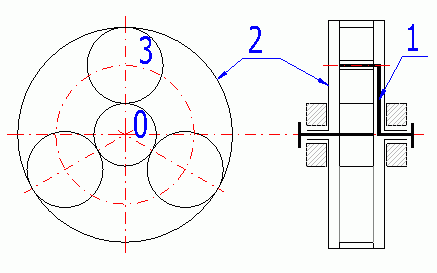
0 - Sun; 1 - Carrier; 2 - Ring gear; 3 - Planet.
If all three members of a simple planetary gearing (0, 1, 2) are free, the system is called a differential (2 degrees of freedom), which enables it to compose / decompose two moves into one. That is used e.g. for machine tools (composition) or for a car differential (move decomposition).
If one of the basic members (0 or 2) is connected to the frame, the system is called planetary gearing (1 degree of freedom), specifically a reductor in case of a drive outwards from the sun or a multiplicator in case of a drive outwards from the carrier. The system with the carrier connected to the frame is called a normal transmission or helical gearing.
Planetary gearings may be arranged in various ways. The most frequent way includes the serial arrangement, where the total transmission ratio (efficiency) is determined by the product of partial transmission ratios (efficiency). The composed gearings often use the possibility to brake individual members, i.e. gear changing.
With respect to the above-specified advantages, the use of planetary gearings is popular in a wide range of applications (e.g. motor vehicle transmissions, building machinery, lifting equipment, marine transmissions, turbine reducers, etc.) The combination of planetary gearing with hydraulic or friction gearing is also common.
The formulas below use the following indexes.
For:
With respect to the possibilities of assembly and functioning of planetary gears, the geometry of the gearwheels cannot be chosen at random. In order to provide proper functioning, the following several conditions must be followed and observed.
The planets of the planetary gearings gear with the suns, possibly with other planets. This calculation applies to the joint mesh of a planet with suns (planet, ring gear). As the planet and the ring gear have the same axis, the centre distance between the planet and both suns must be the same.
It applies for the generally corrected wheels that:
aw (0,1) = aw (1,2)
with aw (0,1)=mt • (z0+z1)/2 • COS(alfat)/COS(alfawt(0,1))
with aw (1,2)=mt • (z1+z2)/2 • COS(alfat)/COS(alfawt(1,2))
For simple planets and uniform planet distribution, the following condition must be complied with:
g = (abs (z0) + abs (z2))/P
With:
g - must be a random integer
P - number of planets
z - number of teeth
This condition provides minimum backlash between the planets vmin (1-2 mm, 0.05 in).
Maximum planets P = int(asin((da1+vmin)/(aw • 2)))
The gearwheel transmissions are divided into:
Force gears - The gear designed mainly for output transfer and transformation, requires strength design/control (e.g. machinery drives, industrial gear boxes.).
Non-force gears - The gear with transferred torsional moment minimum compared to the gearwheel dimension does not require strength design/control (e.g. devices, control engineering.).
The task to design planetary gearing allows significant freedom in the choice of diameter and width parameters of gearwheels on the one hand, while on the other hand it is necessary to comply with a number of conditions (alignment, assembly...) in order to guarantee the gear functions. That is why it is appropriate to proceed in an iterative way and refine the solution and fine-tune the respective parameters gradually.
This procedure provides a quick view of the parameters of the designed gear.
Although such designed gear is normally usable, you can improve its properties
significantly by gradually optimizing the range of parameters. Use the following
procedure in designing:
1. Set the performance parameters of the gearing (transferred output and speed).
[1]
2. Choose the material for all gears, choose the load mode, operating and
production parameters and the required safety coefficients. [2]
3. Perform automatic design -> Press the "Spur gearing"/"Helical gearing"
button. [2.11]
4. Check the results.
Before optimizing the parameters, perform the "Fast (informative) design"
described above first. Then proceed as follows:
1. If you want to use non-standard parameters of the tooth profile, set them in
paragraph [3].
2. Set the gearwheel parameters (number of teeth, pressure angle and helix
angle). [4.1-4.6]
3. Use the slider [4.7] to set the ratio of the sun width to its diameter, press
the "Design gearing" button.
4. Check the dimensions of the designed gear in the schematic drawing. If the
dimensions do not suit you, adjust the ratio of the pinion width and diameter
and recalculate the gear [4.4].
5. In paragraph [5], fine-tune the centre distance, possibly sliding properties
by changing the corrections.
6. Check and assess (compare with the Help) the dimensional and qualitative
indicators. [6; 7; 8]
7. Check the safety coefficients. [9, 10]
The strength parameters do not require handling or controlling when designing a non-force gear. Therefore, choose the proper number of planets [4.1], teeth [4.3] and module [4.9] directly and check the dimensions of the designed gearing.
In this paragraph, set the basic input parameters of the designed gearing.
Use the drop-down menu to choose the required system of units for calculation. After the units are switched, all values will immediately be re-calculated automatically.
Choose the transmission type. The first part on the drop-down menu line specifies which member of the planetary gearing will be the input (you can choose the input power and speed). The second part (after the arrow) specifies the output member. After switching, the speed inputs are also adjusted [1.4] so that the input member speed is non-zero.
Set the power on the input gearing member. The normal values range from 0.1 -
3000 kW / 0.14-4200 HP, and up to 65000 kW /100000 HP in extreme cases.
Press the button on the right to perform the calculation for the maximum
possible power for the current gearing parameters.
Set the speed of the gearing input member. The highest speed may be up to
150,000 rpm. The checked checkbox after the input cells indicates locking of the
respective planetary gearing member. After unchecking, the mechanism acts as a
differential => The speed for two gearing members can be selected.
The output member speed (in bold) is a function of the number of teeth of
individual gearwheels. However, as the number of teeth cannot be designed
randomly, it is appropriate to handle the required output speed in detail in
paragraph [4.0].
Set the requested output member speed. It must be within the range specified in the green cell. After pressing the button on the right, the number of teeth will be designed and selected in order to achieve the requested speed. The number of teeth and speed can be handled in detail in paragraph [14.0].
It is a result of the calculation and cannot be set.
It specifies the planet speed in the carrier. It is important for calculating the capacity of the planet bearing, which is often a critical place of the gearing.
It is the transmission ratio between individual gearing members. The third value is important - the transmission ratio (z2/z0), which indicates the value of the helical gearing used in further calculations.
When designing power gearing, enter other supplementary operational and production input parameters in this paragraph. Try to be as accurate as possible when selecting and entering these parameters as each of them may dramatically affect the properties of the designed gearing.
The option is performed, above all, according to the following aspects:
Usually the principle that the pinion has to be harder than the gear (20-60 HB) is followed, whilst the difference in hardnesses increases with increasing hardness of the gear and the transmission ratio. For quick orientation, the materials are divided into 8 groups marked with the letters A to H. Perform selection of the material in the pop-up list separately for the pinion and for the gear. In case you need more detailed information on the chosen material, proceed to the sheet "Material".
Materials A,B,C and D, so-called. soft gears - The toothing is produced after heat treatment; these gears are characterized by good running-in, do not have any special requirements for accuracy or stiffness of support if at least one gear is made of the chosen material.
Materials E,F,G and H, so-called. hard gears - Higher production costs (hardening +100%, case hardening +200%, nitriding +150%). Heat treatment is performed after production of toothing. Complicated achievement of the necessary accuracy. Costly completion operations (grinding, lapping) are often necessary after heat treatment.
Own material values - In case you wish to use a material for production of toothing that is not included in the delivered table of materials, it is necessary to enter some data on this material. Proceed to the sheet "Materials". The first 5 rows in the table of materials are reserved for definition of your own materials. Enter the name of the material in the column designed for names of materials (it will be displayed in the selection sheet) and fill in successively all parameters in the row (white fields). After filling in the fields, go back to the sheet "Calculation", choose the newly defined material and continue in the calculation.
Setting of these coefficients substantially affects the calculation of safety coefficients. Therefore, try to enter as accurate a specification as possible when selecting the type of loading. Examples of driving machines:
Setting these parameters substantially affects the calculation of safety coefficients. Therefore, try to enter as accurate a specification as possible when selecting the type of loading. Examples of driven machines:
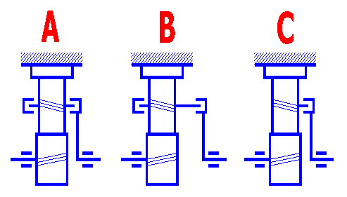
Setting this parameter affects the calculation of the safety coefficient. The type of mounting defines the load unevenness coefficient resulting mainly from the shaft deflections. Use the following definition and picture to choose/estimate the type of mounting.
A. Double-sided symmetrically supported gearing: It is gearing with
the gearwheels mounted symmetrically between the bearings (the distances between
the bearings and wheel edge are the same).
B. Double-sided non-symmetrically supported gearing: It is gearing with
the wheels mounted asymmetrically between the bearings (the distances between
the bearing and wheel edge are different).
C. Overhung gearing: It is gearing with the wheels overhung. The shaft is
attached (fixed) from only one side of the gearwheel.
Type 1: Rigid box, rigid shafts, robust, roller or tapered roller
bearings.
Type 2: Less rigid box, longer shafts, ball bearings.
When choosing the degree of accuracy of the designed gearing, it is necessary to take into account the operating conditions, functionality and production feasibility. The design should be based on:
The accuracy of toothing is chosen to the necessary extent only, because achievement of a high degree of accuracy is costly, difficult and conditioned by higher demands for technological equipment.
Table of surface roughness and maximum peripheral speed
| Degree of accuracy ISO 1328 |
3 | 4 | 5 | 6 | 7 | 8 | 9 | 10 | 11 |
| Degree of accuracy AGMA |
13 | 12 | 11 | 10 | 9 | 8 | 7 | 6 | 5 |
| Max. surface roughness Ra max [nm] | 0.1-0.2 | 0.4 | 0.8 | 1.6 | 1.6 | 3.2 | 6.3 | 12.5 | 25 |
| Max. peripheral speed [m/s] straight teeth | 80 | 60 | 35 | 15 | 8 | 5 | 3 | 3 | 3 |
| Max. peripheral speed [m/s] helical teeth | 100 | 80 | 50 | 30 | 12 | 8 | 5 | 3 | 3 |
Orientation values for options of the degree of accuracy according to the specification.
|
Specification |
Degree of accuracy ISO |
Degree of accuracy AGMA |
| Control gears | 2 - 4 | 13-12 |
| Measuring instruments | 3 - 6 | 13-10 |
| Turbine reducers | 3 - 5 | 13-11 |
| Aviation reducers | 3 - 6 | 13-10 |
| Machine tools | 3 - 7 | 13-9 |
| Aviation engines | 5 - 6 | 11-10 |
| High speed gearboxes | 5 - 6 | 11-10 |
| Passenger cars | 6 - 7 | 10-9 |
| Industrial gearboxes | 7 - 8 | 9-8 |
| Light ship engines | 7 | 9 |
| Rolling mills, locomotives | 8 - 9 | 8-7 |
| Heavy ship engines, tractors | 8 - 9 | 8-7 |
| Building and agricultural machines | 8 - 10 | 8-6 |
| Textile machines | 7 - 9 | 9-7 |
The parameter specifies the desired service life in hours. Orientation values in hours are given in the table.
|
Specification |
Durability |
| Household machines, seldom used devices | 2000 |
| Electric hand tools, machines for short-term runs | 5000 |
| Machines for 8-hour operation | 20000 |
| Machines for 16-hour operation | 40000 |
| Machines for continuous operation | 80000 |
| Machines for continuous operation with log service life | 150000 |
The recommended values of the safety coefficient vary within the range:
Decide whether you wish to design straight or helical toothing. The following recommendations can be used for your option:
With the "Automatic design" the setting of parameters of the gearing is based on the entered power and operational parameters [1.0; 2.0] and on generally applicable recommendations. Manual optimizing can mostly provide toothing with better parameters (weight, dimensions) or enable modifications of the dimensions based on your own constructional requirements.
Set the parameters of machining tool and tooth tip relief in this paragraph. The parameters affect most of dimensions of the toothing, tooth shape and the following strength parameters, stiffness, durability, noise, efficiency and others. If you don't know the accurate parameters of the production tool, use the standardized type from the list box on line [3.1], namely:
1. DIN 867 (a=20deg, ha0=1.25, hf0=1.0, ra0=0.38, d0=0, anp=0deg, ca=0.25)
for calculation in SI units and
3. ANSI B6.1 (a=20deg, ha0=1.25, hf0=1.0, ra0=0.3, d0=0deg, anp=0, ca=0.35) for
calculation in inches.
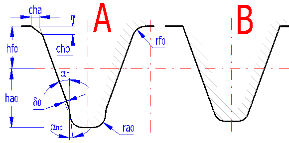
You can define two types of the tool in the form, with protuberance (A) and without protuberance (B). If you define a tool without protuberance, set the protuberance dimension d0=0. Set the tool dimensions according to the dimensions in the picture in the modulus multiples "value" x "modulus" (calculation in SI units) or as a quotient of "value"/"Diametral Pitch" (inch calculation). Choose a pressure angle in paragraph [4]. The base of tooth can be either bevelled or rounded. Therefore choose only one way.
The diagram shows the shape of a tool tooth for wheel/pinion. If you change tool dimensions, press the respective button which will provide redrawing in accordance with the current set values.
An accurate shape of tooth and toothed wheel, check of interferences, etc. is described in the paragraph dealing with graphic output and CAD systems.
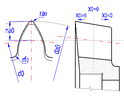
Internal toothing is made, in overwhelming majority of cases, by cutting using a circular tool. For the purposes of this calculation we will consider a tool with basic parameters identical with the designed toothing (an0=an, b0=b, mn0=mn). However, angle b cannot be chosen at random when manufacturing the internal toothing, as it is necessary to proceed from the properties of the machine tool and available tools and it is appropriate to consult this selection with a technologist.
You can see an example of such tool in the picture. The current status of tool sharpening equates its unit correction x0. Resharpening of the tool results in the change of correction and subsequently in the change of tool hub diameter. If the value for correction x0 is unknown, just measure the current hub diameter and use the change of correction x0 [3.13] to adjust the hub diameter da0 [3.14] to a required value.
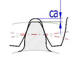
Unit tooth tip relief "ca" affects the diameter of addendum circle. Normally ca=0.25 is chosen which guarantees preventing interference for normally used corrections. If the accurate tool parameters are known, it is possible to choose smaller c*, namely 0.15 to 0.1, and thus achieve increase of profile bite coefficient. Interference can and should be checked on a detailed drawing, see the paragraph dealing with graphic output and CAD systems. Line [3.10] gives minimum tooth tip relief which can be achieved using the selected tool. The selection of smaller tool tip relief is indicated by red color of input field. Button "<" will transfer the minimum value into the input field. Minimum unit tooth tip relief can be reduced by increasing the height of the tool base.
The geometry of the gearing can be designed in this paragraph. The design of the geometry substantially affects a number of other parameters such as functionality, safety, durability or price.
Choose the number of planets. Usually 2 to 6 planets are used; 3 planets are used most often. The green box shows the maximum number of planets possible for the respective number of teeth of the sun and ring gear. If the assembly condition is not complied with, the cell number turns red.
Use line [4.3] to set the number of sun and ring gear teeth. The number of planet teeth is calculated automatically. As the number of teeth in the planetary gearing cannot be chosen at random (see the theoretical part), erroneous or improper combinations of the number of teeth are signalized by a red number. For the sake of simplifying, line [4.2] contains the buttons that enable you to increase/decrease the number of teeth while the number of teeth and addendum modifications are calculated in order to keep the assembly conditions.
The number of planet teeth can be changed in a narrow range from the optimum value (+-2). Perform the change by selecting from the list on line [4.2]. After the change, the values of the addendum modification are calculated automatically in order to comply with the condition of alignment.
In general, the principle applies that increasing the number of teeth (in case of the same distance of axes) results in:
In general, a higher number of teeth is recommended for helical gearing and higher performances.
This angle determines parameters of the basic profile and is standardized to an angle of 20°. Changes in the
pressure angle
a/F affect functional and strength properties. Changes in the meshing angle, however, require non-standard production tools. In case there is no special need to use another meshing angle, use the value of 20°.
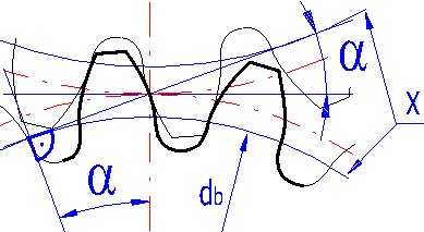
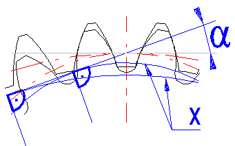
The letter "X" marks the basic circle.
Increasing the meshing angle allows:
Option of values
In case you do not have any special requirements for the designed gearing, it is recommended to use 20°.
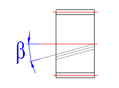
The gearing with helix angle = 0 (spur gearing) is used for slow-motion and
heavily stressed gearings.
The gearing with helix angle > 0 (helical gearing) is used for fast-motion
gearings, it has lower noisiness and better load capacity, and enables a lower
number of teeth without undercutting.
The beta angle is usually chosen from the following line of 6,8,10,12,15,20, 25,30,35,40 degrees.
Use the slider to set the value for the dimensionless coefficient, which defines the ratio of the width of the sun to its diameter [4.8].
This parameter is used to design the size of the module as well as the gearwheel's basic geometrical parameters (width, diameter). The recommended maximum value is given in the right column and depends on the selected gearwheel material, on the method of gearwheel mounting and on the gearing transmission ratio. Use the slider located on line [4.7] to set this parameter. After setting the parameter, press the "Design gearing" button. That way you will design the gearing conforming to the required safety [2.10] and other input parameters.
After the "Gearing design" is over, check the dimensions (gearwheel widths and diameters, weight). If you are not satisfied with the result, adjust the parameter of the pinion width to diameter [4.7, 4.8] and repeat the "Gearing design".
Upon the start of "Gearing design" the modules (DP) are gradually placed into the calculation from the table, the width of the gearing is calculated and the minimum module (DP), which still conforms to the strength conditions, is defined.
Lower values - narrower gearwheel design, larger module, spur gearing
Higher values - wider gearwheel design, lower module, helical gearing
This is the most important parameter that defines the size of the tooth, i.e.
of the gearing. In general, it applies that for a higher number of teeth, a
smaller module can be used (higher P value for inch version of calculation) and
vice versa. In the right drop-down menu, there are standardized module values /
Diametral Pitch and the value selected from this menu is added automatically to
the box on the left.
Use the selection on the right to switch between the option to set the module or
Diametral Pitch.
The width of the gearing of individual gearwheels is measured using a pitch cylinder. After the button on the right is pressed, the values conforming to the selected ratio yd from line [4.7, 4.8] are completed.
Depend on the selected material and type of gearing construction [2.1, 2.2, 2.3, 2.5]. See the previous line for the recommended value range.
This is a common width of both gears on rolling cylinders. If the gears are not in offset positions (Fig. 4.1), it is mostly the width of the gear. This width is used for strength checks of toothing.
In case the check box in this row is enabled, the "Working width of toothing" is filled out automatically with the lower value of the width of toothing from the previous row [4.9]
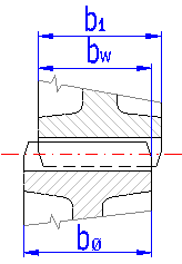
This is calculated as the weight of full cylinders (without weight removal and holes). It serves for quick orientation during the design.
The line always gives the lowest of the coefficients for individual gearwheels. The first column specifies the safety coefficient for surface durability, the second column gives the safety coefficient for bending durability.
As it is not always easy to imagine the mutual movement of all gearwheels (especially for a differential movement), it is possible to simulate the movement of individual gearing members. Specify the step which the input member is to use to move and use the slider to change the input member gear angle.
This is the perpendicular (shortest) distance between non-working sides of teeth. A backlash is necessary to create a continuous layer of lubricant on sides of teeth and to overcome production inaccuracies, deformations and thermal expansion of individual elements of the mechanism. Very small clearances are required in gearing of control systems and instruments and if it is not possible to eliminate it, gearing with automatic take up of backlash is usually used. Great backlash must be chosen with heavily loaded gearing (thermal expansion) and high-speed gearing (hydraulic resistance and shocks with pushing of oil off the inter-tooth gaps.
In practice, the recommended values are chosen empirically and you can follow the recommended values in row [4.21].
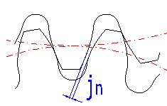
After entering the backlash, the working axis distance [6.10] is modified so that the entered backlash is created.
The correction of external gearing or internal gearing proper may be used to affect a range of parameters. First of all, it is necessary to ensure functioning, and then the performance or strength parameters may be improved. In case of planetary gearing, the situation is more complicated. The correction of individual wheels cannot be changed "randomly". First of all, the alignment must be provided, which means that the centre distance of the sun and the planet must be the same as the centre distance of the planet and the ring gear. That means that the corrections depend on each other and if e.g. the correction of the planet is changed, the correction of the sun and ring gear must also be changed in order to maintain the condition of alignment. In this paragraph, you can choose/change the correction of individual gearwheels while the program controls the gearing parameters and informs you in case of an erroneous or out-of-line setting.
While changing the correction, you can also check the most important qualitative parameters, e.g. mesh ratio, specific slip and safety.
On the left there is a detail of a machine tool (the machining process may be simulated). The accurate shape of the tooth is black and the accurate shape of the machine tool is green. On the right there is a detail of the mutual position of a pitch, tip, root and base diameter in the mesh point (dashed - root diameter, dot-and dash - pitch diameter, solid- tip diameter).
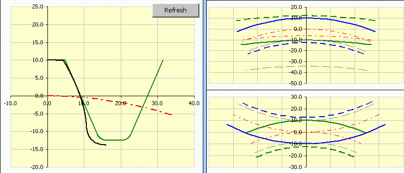
Line [5.2-5.4] specifies some minimum values of corrections in order to achieve the selected parameters of individual gears.
This is the minimum value of a correction which can be used without admissible (minor, tolerable) undercutting of teeth.
This is the minimum value of a correction which can be used without undercutting of teeth.
This is the minimum value of a correction which can be used without tapering of teeth.
In order to maintain the alignment condition, only one correction value can be changed - the planet in this specific case. Other corrections are calculated. You can use the slider to change the addendum modification coefficient for the planet, the current value is displayed on line [5.6]. The change is in steps of 0.1/0.01 of module; you can set the more accurate (own) value on line [5.6]
On line 5.8 you can set the sum of addendum modification coefficients for the sun and the planet and for the ring gear and the planet. Unfortunately, these values cannot be selected randomly, the condition of mutual alignment must be observed (see the theoretical part). The two buttons on the right provide setting of the values in order to keep one of the sums zero, and the other is calculated in order to maintain the alignment condition (aw01 + aw12 = 0).
More frequently, however, the task includes the setting of these values in order to achieve the required axis distance, which is handled on line [5.10].
There is a centre distance for the sun and planet and for the ring gear and planet. Both values (or their absolute value) must be the same. If the values differ, the condition of alignment is not maintained and the gearing cannot function properly. In such case, select the centre distance and calculate the addendum modifications see [5.10]
Probably the most frequent geometrical task will apply to the design of
addendum modification coefficients in order to achieve the required axis
distance. While keeping a reasonable tooth shape, the axis distance for the
specific module and numbers of teeth can be achieved from the interval given in
the green cell. For a different axis distance, you must change the number of
teeth, possibly the gearing module (CP).
Set the required axis distance in the input cell (it must be from the range of
permissible values) and press the "=aw" button on the right. That will perform
the calculation and the values of the sums of addendum modification coefficients
are completed in order to achieve the required axis distance.
After a change in corrections, it is advisable to watch the behavior of these indices. Exceeding critical values is indicated by a change in the number.
Detailed description [8.1] a [8.2]
This is a dimensionless parameter (proportion of the tooth thickness and the module) and depends, above all, on the tooth shape. The following parameters also have certain effects:
Usually it is 0.25 - 0.4. Higher for low values of the addendum modification coefficients and hardened gears. A smaller value than the recommended is indicated by a red text, exceeding the limit of tooth sharpness by a red field.
One of the most frequent optimizing tasks applies to finding such addendum modification coefficients x0, x1 and x2 in order to balance the specific sliding on tooth tips / roots of the sun and planet and the planet and ring gear. The principle is described in professional literature. In this calculation, line [5.14, 5.15] specifies the specific sliding on the tooth root (tip) of the sun and planet and line [5.16, 5.17] the specific sliding on the tooth root (tip) of the planet and ring gear.
Press the button on the right to set such value of addendum modification coefficient x1 in order to achieve the balancing of specific sliding for the pair sun/planet or planet/ring gear. If the recommended values of addendum modification coefficients x0, x1 are to be exceeded, the limit recommended values are used => the required balancing of specific sliding cannot be achieved.
This optimization method is suitable for gears with approximately the same number of teeth and made from the same material. In case the number of teeth differs, the teeth of one gear mesh more frequently than the teeth of the other gear and with balanced specific sliding, the root of the more stressed gear is more prone to pitting.
Therefore, the more appropriate method than using a correction to balance the specific slidings may use the correction in order to achieve the minimum sum of absolute values for all specific slidings. In such case, it is also advantageous that the transmission efficiency increases (losses due to friction are reduced). Press the button on the right to set the value of addendum modification coefficient x1 in order to minimize the sum of all specific slidings.
Detailed information [10].
Use this line to specify which detailed tooth and tool profile is to be displayed. Use the slider on the right to set the tool turn in cut.
This paragraph includes a well-arranged listing of all basic dimensional parameters of toothing. An informational illustration of the most important dimensional parameters is given here. It is recommended to use specialized literature for a more detailed description of individual parameters.
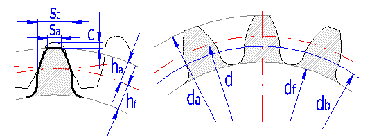
Specification of dimensions according to ISO (DIN)
This is a dimensionless parameter (proportion of the tooth thickness and the
module) and depends, above all, on the tooth shape. The following parameters
also have certain effects:
- higher number of teeth [4.1] = greater sa*
- lower addendum modification coefficient [5.4] = greater sa*
- smaller meshing angle [4.2] = greater sa*
- greater helix angle [4.3] = greater sa*
- higher addendum coefficient [3.1]= smaller sa*
Recommended values
Usually it is 0.25 - 0.4. Higher for low values of the addendum modification
coefficients and hardened gears. A smaller value than the recommended is
indicated by a red text, exceeding the limit of tooth sharpness by a red field.
In practice, it is sometimes achieve certain exact values of the head circle. If the original gearing dimensions should be maintained, it is possible to slightly change the head circle diameter by changing the tooth tip backlash ca* in the section [3.11]. The following three lines are used to simplify this calculation. On the second line, the possible range of the head circle diameters are mentioned. Enter the required diameter on the third line. Press the "->ca1" ("->ca2") button to change the tooth tip backlash of the pinion (wheel).
This paragraph includes the minimum numbers of teeth which can be used with zero correction without undercutting or tapering of teeth.
This includes the parameters which inform us of the quality of the designed toothing. It is advisable to compare them with the recommended values.
For smooth meshing of gears, it is necessary that the other pair of teeth enters in meshing before the first pair is released. The contact ratio in the face plane says how many teeth are in meshing simultaneously. With the value ea=1 this corresponds to a limit case when only one pair of teeth is in meshing at the given moment. With the value
According to the complexity of the gearing, this parameter should not be lower than 1.1 to 1.2.
This is the sum of transverse contact and overlap ratios.
This is specified using the same recommendations as
Lines [8.7 - 8.10] enable more precise specification of the dimensions of individual wheels. After checking the box on the line [8.7], you can specify relevant dimensions according to the headline of this section. Press the "<=" button [8.7] to fill in the pre-selected values.
The shape of individual wheels is displayed acc. To the specification. If no inner wheel dimensions are specified, the wheels are considered as solid cylinders in the calculation.
Using the "Automatic design " [2.10], gearing design [4.4] and the exact mn calculation [4.6] will cancel the wheel specification and the solid cylinders will be used instead.
This parameter gives the ratio between the root diameter and the inner diameter of the toothed rim dx/df. It is characterized with values in a range from 0 to 1. In case the evaluated gear will be produced as a solid disc (without weight reduction), the parameter = 0. This parameter affects calculations of critical speed of the gearing.
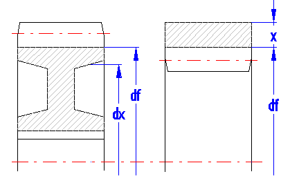
It is calculated as a sum of individual cylindrical parts (ring gear, stem and hub). If the relief coefficient di/df = 0, the wheel weight is calculated as the weight of the solid cylinder (which is sufficient in most cases). This is used for a quick reference in the design.
This is the speed at which the angle speed is the same as the proper angle vibration frequency of the gearing.
This is the ratio of pinion speed and "Critical speed".
In case the designed gearing works in the range of critical speed (N ~ 1), the resonance ratio N is indicated by a red number. In such cases, modifications of the designed gearing (changes of numbers of teeth) or consultations with a specialist are recommended.
The approximate calculation given in the theoretical part of the Help is used for the calculation.
There are performance losses in the gearing, losses in bearings and their sum.
In this part, the calculation method of some coefficient should be specified. After pressing the button, the default values are set based on the requirements mentioned in the paragraph [2.0]
There are three calculation methods available - (B2006), (C2006), and (C1996).
The method B is suitable for all the types of spur gears. It is relatively complicated and may give completely unrealistic KV values, if the materials or the degree of accuracy are not properly selected. Therefore it is possible to set the maximum limit for the calculation (pre-set to 5.0). If this limit is exceeded, it is recommended to check the selected material and the degree of accuracy in proportion to the gearing load. The method C may be used with some limitations (see the theoretical part).
There are three calculation methods of
It depends on a range of factors, firstly on the specific dimensions and the
design of the gearing (see the theoretical part). It is possible to set all
these parameters in details in the paragraph [18.0]. If the input parameters are
not selected properly, the
Press the "=>" button to move to the
According to the ISO 6336-5 standard, it is recommended to reduce the value
By selecting "Automatic" one can choose a coefficient calculation method based on the selected materials. If required, you can select the calculation method directly from the list.
If you select an optimum modification of the tooth profile with respect to
the tooth deflection due to an immediate load level, select "Optimum profile
modification". Selection of this parameter influences the calculation method of
the coefficients
Use the drop-down menu to choose the type of oil. For less stressed gearings, you can use mineral oil; for higher speeds, higher transmitted power and higher efficiency requirements, it is more appropriate to use synthetic oil.
Some advantages of synthetic oils
- Reduction of total losses of 30% and more
- Reduction in oil working temperature
- Increasing the interval for oil replacement by 3-5x (reduction in maintenance
costs)
On the other hand, the price is higher, there may be problems with plastic or rubber parts, and the mixing with mineral oil is limited.
The recommended viscosity is chosen based on the hardness of the wheel material and the circumferential velocity. If the recommended value is not suitable, check the radio button and enter your own value.
If the first item in the "Automatic" list is selected, the applied surface roughness will be derived from the selected degree of accuracy. However, a different value may be set, if it is known.
It considers a higher capacity for a limited number of load cycles. The coefficient is derived from interpolations of relevant damage line (ISO6336, AGMA 2001-D04). For the number of cycles N = 1010 (marked as ∞), the coefficient value is selected in the range of 0.85 to 1.00. The value of 0.85 is intended for the critical operation whereas the value of 1.00 may be used when the optimum lubrication, material, production and experience are ensured.
If the strength values of the used material are set in accordance with the ISO 6336-5 standard, the stress correction factor is YST = 2. In case the strength values specified for the test sample without a notch are used, the stress correction factor is YST = 1 (for materials from the material database for this calculation).
The toothed wheel notch (e.g. ground notch in the tooth root transition near the critical cross-section) usually increase the stress concentration caused by the root transition; therefore the stress concentration coefficient is higher accordingly. If the notch is located near the critical cross-section, the coefficient YSg is used instead of YS.
If the radio button is checked, the YS value is substituted by the YSg value. The YSg coefficient values are calculated in the paragraph [18.0] that can be accessed by pressing the "=>" button.
Two basic strength calculations are usually carried out, namely for bend and for contact. The following safety coefficients are calculated in this calculation:
As initial values of the safety coefficient you can use:
Safety coefficients can then be modified according to general recommendations for options of safety coefficients and according to your own experience.
This paragraph specifies two basic check dimensions
of toothing. They are the dimension across the teeth W [11.3] and dimension
across the rolls and balls M [11.6]. After checking the check box to the right
of the value of number of teeth that the measurement applies to [11.2] and the
diameter of roll/ball [11.5] you can set your own values. Other check dimensions
required for production of toothing are tied to fitting of toothed wheels and
manufacturing method and therefore close cooperation of a designer and a
technologist is appropriate.
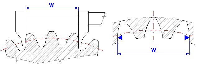
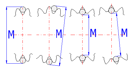
If you try to find the parameters of an unknown wheel, it is possible to use this tool. Measure the relevant check dimension on the wheel, enter it in the respective input field and the calculation will modify the correction x1 (SumX) so that the calculated W or M dimension agrees with the measured value.
This part contains a complete calculation of tolerances in accordance with ISO 1328 (ANSI/AGMA 2015-1-A01). The tolerance calculation is linked with the main calculation and the tolerances are calculated for a current accuracy, module, diameters and the width of the wheels. The tolerances are then used for the safety coefficient calculations.
If you need to calculate the tolerances for different toothing diameters independent on the actual calculation, check the radio button on the line [11.14]. The colour of the input boxes [11.15, 11.16, and 11.17] will change to white and you can enter your own values of the toothing dimensions.
Possible ranges of imputs for f''I
and F''i:
Accuracy grade Q: 4-12
Modul mn: 0.2-10
Diameter d: 5-1000
Facewidth b: 4-1000
In loaded gearing, forces which are transferred to the machine structure arise. In order to ensure proper dimensioning of the equipment, knowledge of these forces is essential. The orientation of the forces is described in the picture, the size of forces and loads is specified in this paragraph [12.1 - 12.10].

It is the force that results from the effects of the planet carrier on the planet (or vice versa).
The rotation of the carrier results in sufficient force caused by the
rotation of the planets around the central axis. This force must be retained by
the planet bearing (bearings) and must be considered in the bearing design. This
force may be critical for higher speeds and its precise value should be found
from the accurate model of the planet.
The force in the calculation is derived from the estimated planet weight,
including the unloading, see [8.4].
It is a vector sum of forces Fc-p and Fc [12.5, 12.6].
The value of torque used for strength checks.
The speed used for strength checks.
In case of helical gearing, there is an additional bending moment which affects the planet and which must be considered in the design of planet bearings and shaft. There is no additional bending moment in the case of the suns (sun and ring gear).
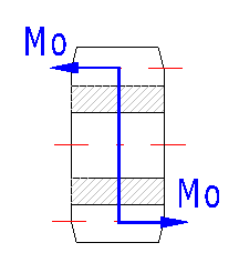
This is another important qualitative parameter which affects the required gearing accuracy [2.6] and the method of lubrication (Gear lubrication). The maximum recommended speed for the selected accuracy degree is shown in the green cell on the right.
It is another qualitative factor used in the calculation of "Tooth load unevenness coefficient".
This paragraph specifies the material characteristics of the chosen material for all gears.
The construction requirements may also apply in achieving the accurate
output speed. The procedure in this paragraph may be used to do this. In the
calculation, the respective number of teeth for the ring gear is calculated for
all combinations of the teeth of the sun and planet from the range defined on
line [14.3, 14.4]. Next, the speed of the output member is calculated for each
combination. The results are displayed in table [14.5].
Press the button on line [14.6] to start the calculation. When it finishes, the
best result is transferred automatically back into the main calculation. After
you have chosen a different solution from the table, the respective number of
teeth is transferred into the main calculation again.
This paragraph gives designs of shaft diameters (steel) which correspond to the desired loading (transferred power, speed). These values are orientation values only; it is advisable to use a more exact calculation for the final design.
In practice, you face quite frequently a situation where the toothing is unknown and it is necessary to calculate its parameters (competition comparison, production of a spare gear, etc.). Therefore, this provides a simple tool to facilitate the primary calculation of the basic parameter - module.
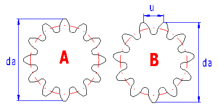
It is obvious that the mentioned procedure needs certain skills and experience, nevertheless, in case of common gearing, where production using common standardized tools and procedures can be assumed, this procedure leads to quite reasonable results.
Auxiliary calculations are available in this paragraph. When entering values, use the same units as in the main calculation. To transfer the entered and calculated values to the main calculation, press the button "OK".
The KHb and YSg calculation is described below.
The KHb calculation consists of the sequence of several steps
1) Calculation of fsh = f(Fm, dsh, K',
l, s, b1,
d1)
2) Calculation of fma = f(fHb1
, fHb2)
... [11.29]
The fsh and fma values (or fsh2, fca, fbe) are used to calculate the value of Fbx
3) Calculation of Fbx
= f(fsh, fma, fsh2, fca, fbe, B1, B2)
4) Calculation of yb
= f(Fbx, sHlim)
5) Calculation of Fby
= f(Fbx,
yb)
6) Calculation of KHb = f(Fby,
Fm,
cgb,
b)
The range of coefficients may be specified using several methods and the designed / checked gearing must be well understood. Press "Default setting" for the basic design. By doing this, the calculation will be set to the basic conditions as follows.
- [17.5] ... set according to the selection of [2.5]
- [17.7, 17.8] ... dimensions estimated from the gearing size and setting of
[18.8]
- [17.14, 17.15] ... set according to the selected degree of accuracy [2.6]
Then you can gradually enter and set up the parameter that are known or can be estimated.
You can enter your own values after checking the check box next to the relevant input.
It is a pre-selected value based on the root diameter of the pinion and the minimum shaft diameter [8.4]. If you know the shaft diameter, check the radio button and enter your own value.
Select the type of gearing.
Select a relevant pinion mounting from the list, see the picture. Pre-set according to [2.5].
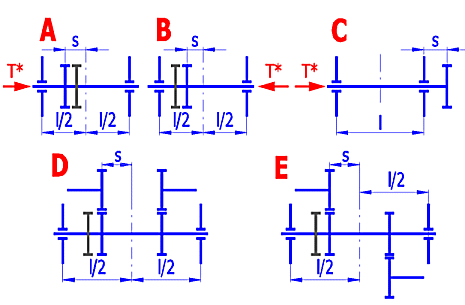
The "l" and "s" values are preliminarily derived from the wheel width and from the selected mounting of the gearing [17.5]. After checking the radio button, you can enter your own values.
The values of fsh, fsh2, fma, fca, and fbe describe deformations of the toothed wheels, wheel tolerances, and mounting tolerances. The values of fsh2, fca and fbe are not considered in this calculation and they can be zero unless you solve a complete equation to calculate Fbx [17.15]. The values of fsh and fma may be directly entered, or the values calculated based on the parameters on the previous lines may be used.
Select the apropriate modification of the tooth slope from the list. See ISO6336:1(2006) for more details.
Select the Fbx calculation from the list.
1. Proper value
2. Gear pairs of which the size and suitability of the contact pattern are not
proven and the bearing pattern under load is imperfect
3. Gear pairs with verification of the favourable position of the contact
pattern (e.g. by modification of the teeth or adjustment of bearings)
4. When, apart from pinion body and pinion shaft deformations, those of the
wheel / wheel shaft and the gear case and also the displacements of the
bearings.
Press "OK" button to return back to the paragraph [9.0]. At the same time, the KHb calculation is set up in the calculation of the coefficients in accordance with ISO6336.
The toothed wheel notch (e.g. ground notch in the tooth root transition near the critical cross-section) usually increase the stress concentration caused by the root transition; therefore the stress concentration coefficient is higher accordingly. If the notch is located near the critical cross-section, the coefficient YSg is used instead of YS.
Fill in the notch parameters, see the picture. By pressing the "OK" button, you return to the paragraph [9.0] and the YS coefficient is substituted by YSg.
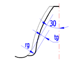
The material type for which you want to determine the material properties can be selected from the list.
The relations used are specified for three levels of the material quality - ML, MQ and ME.
- ML represents the weakest material quality and its heat treatment process
requirements during the toothed wheel manufacturing.
- MQ represents requirements that may be satisfied by a skilled manufacturer
with reasonable production costs.
- ME represents requirements that must be satisfied to achieve a high
operational reliability.
Enter the surface hardness. The material parameters are determined by its type and hardness. At the end of the line you can find the hardness range for which the parameter calculations are applicable. The hardness may be entered in various units (HV, HB and HRC).
If you enter your own material values and you will add the material in the table of materials. This marking will be used to choose some of the coefficients in the strength calculation.
If the radio button on the line [18.5] is checked, it is possible to enter the own material description that will be mentioned in the table of materials and will be used for the material selection in the paragraph [2.0].
Select one of the 5 lines intended for the user defined materials from the list. When the values are transferred, the original content in the table of materials will be overwritten without any caution.
Use the following table for your decision on the manner of lubrication of the gearing.
| Type of lubrication | Peripheral speed in | |
| [m/s] | [ft/min] | |
| Oil-bath lubrication | < 12 | < 2400 |
| Pressure spray lubrication | > 12 | > 2400 |
| Oil-mist lubrication | > 60 | > 12000 |
Information on options of 2D and 3D graphic outputs and information on cooperation with 2D and 3D CAD systems can be found in the document "Graphic output, CAD systems".
These parameters set beveling of the gear according to the illustration.
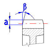
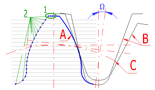
Besides standard display which is used in drawings of assemblies and details, it is also possible to draw a detailed image of the tooth, detail of entire wheel, drawing of wheel engagement and drawing of the tool. Tooth flank is calculated from the simulation of the tool bite with the machined wheel which enables determining the exact tooth shape including the tooth flank. A detailed drawing of the whole wheel can be used as a document for manufacturing an accurate model in 3D CAD system, or as input data for manufacturing the wheel.
The table on sheet "Coordinates" gives the coordinates of points on the right side of the tooth line in the system of X,Y coordinates with point 0,0 in the wheel centre. In order to recalculate and generate the current coordinates according to the settings from paragraph [19] press button "Refresh".
Production tool (B) with dimensions defined in paragraph [3] is gradually rolled away along the circle (C) with step of angle W and thus creates the tooth line (A) in individual points (2).
Specify the number of teeth which shall be drawn in partial drafting.
Define the number of points (sections) on the tooth tip, see picture [19.4],
reference (1).
Range of permitted values: <2 - 50>, recommended: 5
Define the number of points (sections) which form a complete tooth flank, see
picture [19.4], reference (2).
Range of permitted values: <10 - 500>, recommended: 30 and more
It defines the increment of angle for rolling (turning) of the tool during
machining of the tooth flank see picture [19.4], angle W.
Extent of permitted values: <0.02 - 10>, recommended: 0.5
Defines how many positions during the drawing of tooth engagement will be
displayed.
Extent of permitted values: <3 - 100>, recommended: 20
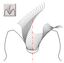
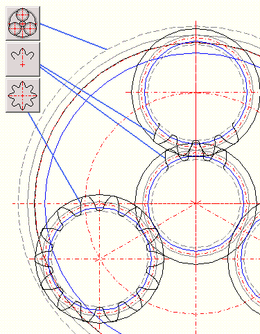
As it is necessary and appropriate to check tooth engagement as well as potential collisions of teeth for internal toothing, the drawing of complete engagement of outer as well as inner gear is generated for internal toothing. In this case, number of copies of teeth during the check of engagement [19.9] specifies number of pinion copies.
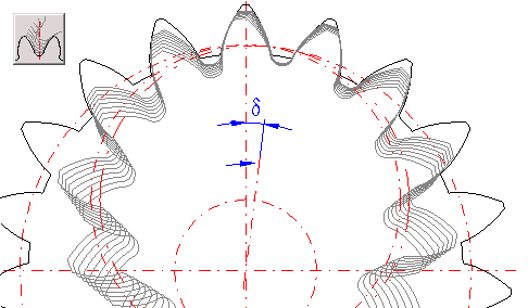
Gives turning of the pinion between individual copies of the pinion which are generated during the check of engagement.
Switch "Drawing without axes" defines if the axes will be removed in the inserted drawing.
You can set the angle to affect the first tooth angle (the tooth gap for the internal gearing) towards the respective gear centre. For the zero gear angle, the first tooth is drawn upwards on the vertical axis. The positive angle turns the respective gear in the counter-clockwise direction. In order to simplify the setting of the position (gear angle) of individual gearwheels or their parts, the four buttons on this line are used.
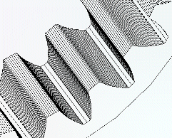
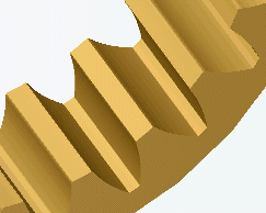
Example of 3D model
Information on setting of calculation parameters and setting of the language can be found in the document "Setting calculations, change the language".
General information on how to modify and extend calculation workbooks is mentioned in the document "Workbook (calculation) modifications".
Material list - Method of heat treatment
1...Non-treated thermally, annealed
normalizationally
2...Upgraded
3...Cemented, hardened, surface hardened
4...Nitrided
ISO 6336-1:2006
- Calculation of load capacity of spur and helical gears - Part 1: Basic
principles, introduction and general influence factors
- Calcul de la capacité de charge des engrenages cylindriques a dentures droite
et hélicoidale - Partie 1: Principles de base, introduction et facteurs généraux
d'influence
- Výpočet únosnosti čelních ozubenych kol s přímými a šikmými zuby - Část 1:
Základní principy, doporučení a obecné ovlivfňující faktory
ISO 6336-2:2006
- Calculation of load capacity of spur and helical gears - Part 2: Calculation
of surface durability (pitting)
- Calcul de Ia capacité de charge des engrenages cylindriques à dentures droite
et hélicoidale - Partie 2: Calcul de la résistance à la pression de contact (piqure)
- Výpočet únosnosti čelních ozubených kol s přímými a šikmými zuby - Část 2:
Výpočet trvanlivosti povrchu (pitting)
ISO 6336-3:2006
- Calculation of load capacity of spur and helical gears - Part 3:
Calculation of tooth bending strength
- Calcul de la capacité de charge des engrenages cylindriques à dentures droite
et hélicoïdale - Partie 3: Calcul de la résistance à la flexion en pied de dent
- Výpočet únosnosti čelních ozubených kol s přímými a šikmými zuby - Část 3:
Výpočet pevnosti v ohybu zubu
ISO 6336-5:2003
- Calculation of load capacity of spur and helical gears – Part 5: Strength and
quality of materials
- Calcul de la capacité de charge des engrenages cylindriques à dentures droite
et hélicoïdale – Partie 5: Résistance et qualité des matériaux
- Výpočet únosnosti čelních ozubených kol s přímými a šikmými zuby – Část 5:
Údaje o pevnosti a kvalitě materiálů
ISO 1265
- Metalic materials - Conversion of hardness values
- Matériaux métalliques - Conversion des valeurs de dureté
- Metallische Werkstoffe - Umwertung von Hartewerten
- Kovové materiály - Převod hodnot tvrdosti
ISO 1328-1:1997
- Cylindrical gears - ISO system of accuracy - Part 1: Definitions and allowable
values of deviations relevant to corresponding flanks of gear teeth
- Engrenages cylindriques - Systéme ISO de precision - Partie 1: Définions et
valeurs admissibles des écarts pour les flanc homologues de la denture
- Toleranzensystem ISO - Teil 1: Toleranzen fur Flankenlinienabweichungen
- Čelní ozubená kola - Soustava přesnosti ISO - Část 1: Definice a mezní úchylky
vztažené na stejnolehlé boky zubů ozubeného kola.
ISO 1328-2:1997
- Cylindrical gears - ISO system of accuracy Part 2: Definitions and
allowable values of deviations relevant to radial composite deviations and
runout information
- Engrenages cyindriques - Systéme ISO de precision Partie 2: Definitions et
valeurs admissibles des ecarts composés radiaux et information sur le faux-rond
- Čelní ozubená kola - Soustava přesnosti ISO - Část 2: Definice a hodnoty
dovolenych úchylek relevantní k radiálním kinematickým úchylkám a informativně k
obvodovému házení.
ISO 1122-1:1998
- Vocabulary of gear terms - Part 1: Definitions related to geometry
- Vocabulaire des engrenages - Partie 1: Définitions géométriques
- Slovník termínů ozubení - Část 1: Definice vztahující se ke geometrii
ANSI/AGMA 2001-D04
AMERICAN NATIONAL STANDARD Fundamental Rating Factors and Calculation Methods
for Involute Spur and Helical Gear Teeth
AGMA 908-B89
Geometry Factors for Determining the Pitting Resistance and Bending Strength of
Spur, Helical and Herringbone Gear Teeth
ANSI/AGMA 2015- 1-A01
Accuracy Classification System - Tangential Measurements for Cylindrical Gears
ANSI/AGMA 2015-2-A06
Accuracy Classification System - Radial Measurements for Cylindrical Gears
^