This part contains a summary of some theoretical information and formulas related to the geometry design, calculation of force and performance parameters as well as the strength control of involute gearing. These data were used in the calculations below.
Some of the most important formulas for calculation of the gearing geometry are specified below. In the formulas, indexes 1 and 2 are used for a pinion and a wheel (which is a pair: a sun and a planet, or a planet and a ring gear). For the internal gearing (ring gear), a negative value for the number of internal gear teeth is used, i.e. also a negative value for the centre distance and diameters.
In the case of planetary gearing, the individual gears are dependent on each other and the gearing must be handled as a whole, including the respective constraining conditions (see below).
Basic profile parameters: mn (module, DP for inch calculation), a (pressure angle), ha*, c*, rf* (cutting tool parameters)
Pinion and wheel parameters: z1, z2 (number of teeth of pinion and wheel), x1, x2 (addendum modification), b (helix angle), b (width of gearing)
Approaching and withdrawal of the production tool from the gear center changes the shapes and therefore also properties of the involute toothing. This creates corrected toothing. The illustration shows:

Correction (addendum modification) of toothing enables:

Example of a tooth profile (z=10, a=20;
When determining values of corrections, first it is necessary to fulfill functional requirements for toothing, where the most important items include
After securing function requirements, it is possible to further optimize corrections in order to improve one or more important toothing parameters. From the frequently used optimizing methods, it is possible to optimize the toothing in order to balance specific slips [5.14 - 5.17] and minimize specific slips [5.18]. For other optimizing processes there is a wide range of recommendations in professional literature, namely the so-called diagrams (charts) of limit corrections, providing a clear view of possibilities and selection of corrections.
Torsional moment
Mk [Nm] = Pw * 9550 / n .............. (SI units)
T [lb.in] =
Pw, PP ... power [kW, HP]
n ........... speed [/min]
Power (Spur gear - Rack)
Pw = Ft * v / 1000
Ft ... Tangential force
v .... Rack speed
Ft = Mk * 2000 / dw
dw ... Operating pitch diameter
MK ...
Axial force
Fa = Ft * tan(b) / cos(awt)
Radial force
Fr = Ft *
Normal force
Fn = (Ft2 + Fa2 + Fr2)0.5
Bending moment
Mo = Fa * (dw / 2000)
The losses in planetary gearing can be divided into losses due to idle run and losses due to loading. The losses due to idle run (lubrication, unloaded mesh, bearings) are difficult to specify analytically and in general, they are significantly lower than losses due to loading. The losses due to loading arise during power transmission and include:
The loss coefficient can be approximately described according to the formula:
Spur gearing: zz = 0.5 • f •
p
• e • (1/z1 +- 1/z2)
Helical gearing: zz
= 0.25 / cos(b) • f •
p • e •
(1/z1 +- 1/z2)
with:
z1, z2 - number of teeth
f - friction coefficient (0.04 - 0.08)
e - mesh ratio
b - helix angle
Plus sign (+) for external gearing, (-) for internal gearing.
The loss output can be determined from the relation:
PVL = w • F • f • r
with:
w - angular velocity
F - resulting bearing loading (carrier, centrifugal force)
f - friction coefficient (0.001 - 0.005)
r - mean bearing radius
For the calculation of loss (efficiency) of the planet gearing, we will use the losses in the helical gearing (carrier stopped) with:
with:
zz0/z1 - loss coefficient sun - planet
zz1/z2 - loss coefficient planet - ring gear
z0,z2 - number of teeth of the sun and ring gear
For individual cases of output flow, it applies for the loss calculation:
| z = ir • zr / (ir - 1) | Sun => Planet (carrier) |
| z = zr | Sun => Ring gear |
| z = ir • zr / (ir - 1 + zr ) | Planet (carrier) => Sun |
| z = - zr / (ir - 1) | Planet (carrier) => Ring gear |
| z = - zr / (ir - 1 - ir • zr) | Ring gear => Planet (carrier) |
| z = zr | Ring gear => Sun |
Planetary gearings consist of a system of gearwheels and a carrier. The so-called suns are aligned with the carrier and the central axis of the gear mechanism. The planets are the gearwheels mounted in a pivoting way on the carrier and they mesh with the suns or with each other. The planets may have one, two or more gearings. Two or multi-speed planets have more constructional variants with wider possibilities; however, they are more complex and expensive to manufacture.
You can see an example of a simple planetary gearing with single-speed toothing of the planet below. This basic type of planetary gearing is also handled in complex in this program.
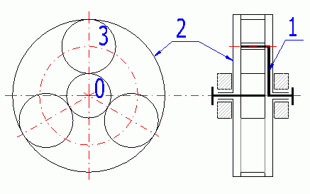
0 - Sun; 1 - Carrier; 2 - Ring gear; 3 - Planet.
If all three members of a simple planetary gearing (0, 1, 2) are free, the system is called a differential (2 degrees of freedom), which enables it to compose / decompose two moves into one. That is used e.g. for machine tools (composition) or for a car differential (move decomposition).
If one of the basic members (0 or 2) is connected to the frame, the system is called planetary gearing (1 degree of freedom), specifically a reductor in case of a drive outwards from the sun or a multiplicator in case of a drive outwards from the carrier. The system with the carrier connected to the frame is called a normal transmission or helical gearing.
Planetary gearings may be arranged in various ways. The most frequent way includes the serial arrangement, where the total transmission ratio (efficiency) is determined by the product of partial transmission ratios (efficiency). The composed gearings often use the possibility to brake individual members, i.e. gear changing.
With respect to the above-specified advantages, the use of planetary gearings is popular in a wide range of applications (e.g. motor vehicle transmissions, building machinery, lifting equipment, marine transmissions, turbine reducers, etc.) The combination of planetary gearing with hydraulic or friction gearing is also common.
The formulas below use the following indexes.
For:
With respect to the possibilities of assembly and functioning of planetary gears, the geometry of the gearwheels cannot be chosen at random. In order to provide proper functioning, the following several conditions must be followed and observed.
The planets of the planetary gearings gear with the suns, possibly with other planets. This calculation applies to the joint mesh of a planet with suns (planet, ring gear). As the planet and the ring gear have the same axis, the centre distance between the planet and both suns must be the same.
It applies for the generally corrected wheels that:
aw (0,1) = aw (1,2)
with aw (0,1)=mt • (z0+z1)/2 • COS(alfat)/COS(alfawt(0,1))
with aw (1,2)=mt • (z1+z2)/2 • COS(alfat)/COS(alfawt(1,2))
For simple planets and uniform planet distribution, the following condition must be complied with:
g = (abs (z0) + abs (z2))/P
With:
g - must be a random integer
P - number of planets
z - number of teeth
This condition provides minimum backlash between the planets vmin (1-2 mm, 0.05 in).
Maximum planets P = int(asin((da1+vmin)/(aw • 2)))
This is a standard gearing calculation, where the rack is in gear with the pinion. The manufacturing tool profile can be specified both for the pinion and the gear rack.
It is possible to select the number the pinion teeth, the pressure angle and the tooth slope. Since it has no meaning to correct the gear rack in this case, only the pinion correction is possible (axial distance, gear condition and strength parameter improvement).
In the calculation it is possible to enter the tangential force, which is the force of the gear rack acting on the pinion, and the speed of the gear rack (pinion circumferential speed). These two values are then used to calculate the power and torque transferred via the pinion. Since it is possible to use the gear rack for a range of various design solution, it is then necessary to calculate (estimate) and transfer the transmission requirements on these two values.
Since there are no standards related to the strength calculation of the pinion in gear with the rack, the ISO6336(ANSI/AGMA2001-D04) standard is used for the strength calculation. The gear rack is replaced by a toothed wheel with a high number of teeth (1 000 teeth).
There is no specific methodology of specifying the critical speed for a gear rack application. As a rough estimate, the calculation of two toothed wheels may be used (the gear rack is substituted by a toothed wheel. For a light rack that is not connected to the structure, use the coefficient sR/h=1; if the rack is connected to the structure, use the value of 20.
To determine the lifetime coefficient (YNT, ZNT), a number of cycles must be known. Enter the number of the pinion and gear rack loading cycles.
In the following paragraphs, the method of the bearing capacity calculation is described. The ISO6336:2006 standard is used for the calculation. The description includes the key formulas used as well as the notes important to understand the calculation and to operate this application. This text does not replace the full text of the standards used.
This part of ISO 6336 presents the basic principles of, an introduction to, and the general influence factors for, the calculation of the load capacity of spur and helical gears.
Ft = 2000 * T1,2 / d1,2 = 19098 * 1000 * P / (d1,2
* n1,2) = 1000 * P / v
w1,2 = 2000 * v / d1,2
= n1,2 / 9549
Ft ... (nominal) transverse tangential load at reference cylinder per mesh
T1,2 ... nominal torque at the pinion (wheel)
d1,2 ... reference diameter of pinion (wheel)
P ... transmitted power
n1,2 ... rotation speed of pinion (wheel)
v ... tangential velocity (without subscript, at the reference circle
=tangential velocity at pitch circle)
w1,2 ... angular velocity of
pinion (wheel)
The application factor, KA, is used to modify the value of Ft to take into account loads additional to nominal loads, which are imposed, on the gears from external sources. The empirical guidance values in table B.1 ISO 6336-6 can be used (for industry gears and high speed gears).
(The internal dynamic factor KV makes allowance for the effects of gear tooth accuracy grade as related to speed and load.
There are three calculation methods (B2006), (C2006) a (C1996).)
The method B is suitable for all the types of spur gears. It is relatively complicated and may give completely unrealistic KV values, if the materials or the degree of accuracy are not properly selected. Therefore it is possible to set the maximum limit for the calculation (pre-set to 5.0). If this limit is exceeded, it is recommended to check the selected material in proportion to the gearing load.
Internal dynamic factor KV(B)
N = n1 / nE1
For N < NS (Subcritical range)
NS = 0.5 + 0.35 * ( Ft * KA / b )0.5
...... [ Ft * KA / b < 100 ]
NS = 0.85 ...... [ Ft * KA / b >= 100 ]
KV(B) = ( N * K ) + 1
K = ( CV1 * BP ) + ( CV2 * Bf ) + (
CV3 * BK )
BP = c' * fpb eff / ( Ft
* KA / b )
Bf = c' * fta
eff / ( Ft * KA / b )
BK = abs (1 + c' * Ca / ( Ft
* KA / b ))
For Ns < N < 1.15 (Main
resonance range)
KV(B) = ( CV1 * BP ) + ( CV2
* Bf ) + ( CV4 * BK )
+ 1
For N >= 1.5 (Supercritical range)
KV(B) = ( CV5 * BP ) + ( CV6
* Bf ) + CV7
For 1.15 < N < 1.5 (Intermediate range)
KV(B) = KV(N=1.5) + (
KV(N=1.15) - KV(N=1.5)) / 0.35 * (1.5 - N)
Coeficients
|
|
1.0 < eg <=2.0 | eg > 2.0 |
| CV1 | 0.32 | 0.32 |
| CV2 | 0.34 | 0.57 / (eg - 0.3) |
| CV3 | 0.23 | 0.096 / (eg - 1.56) |
| CV4 | 0.90 | (0.57 - 0.05 * eg ) / (eg - 1.44) |
| CV5 | 0.47 | 0.47 |
| CV6 | 0.47 | 0.12 / (eg - 1.74) |
| CV7 | 1.0 < eg <=1.5 | 0.75 |
| CV7 | 1.5 < eg <=2.5 | 0.125 * sin(p * (eg - 1.74)) + 0.875 |
| CV7 | eg > 2.5 | 1.0 |
| Cay1,2 | 1 / 18 * (sHlim1,2 / 97 - 18.45)2 + 1.5 | |
| Cay | 0.5 * (Cay1 + Cay2) | |
| Ca | Ca = Cay | |
Internal dynamic factor KV(C)
Method C supplies average values which can be used for industrial transmissions and gear systems with similar requirements in the following fields of application:
Method C can also generally be used, with restrictions for the following fields of application:
Method (C2006) is different from (C1996) by adding the
coefficient K3.
Example for input values KA * Ft / b = 100; v = 3 m / s; Q = 7 and straight
teeth.
1996.gif)
2006.gif)
KV(C..1996)
KVa,b = 1 + (K1 / ( Ft * KA
/ b ) + K2) * v * z1 / 100 * (u2 / (1 + u2))0.5
... [ eb
= 0; eb
>= 1.0]
KV(C..2006)
KVa,b = 1 + (K1 / ( Ft * KA
/ b ) + K2) * v * z1 / 100 * K3 * (u2 / (1 + u2))0.5
... [ eb
= 0; eb
>= 1.0]
KV = KVa - ea* ( KVa - KVb ) ... [0 < eb < 1.0]
Coeficients
| K1 (Accuracy grades as speclfled in ISO1328-1) | K2 | ||||||||||
| 3 | 4 | 5 | 6 | 7 | 8 | 9 | 10 | 11 | 12 | All | |
| Spur gears eb = 0 | 2.1 | 3.9 | 7.5 | 14.9 | 26.8 | 39.1 | 52.8 | 76.6 | 102.6 | 146.3 | 0.0193 |
| Helical gears eb >=1.0 | 1.9 | 3.5 | 6.7 | 13.3 | 23.9 | 34.8 | 47.0 | 68.2 | 91.4 | 130.3 | 0.0087 |
| SRC = v * z1 / 100 * (u2 / (1 + u2))0.5 | |||||||||||
| K3 = 2.0 ...... [SRC <= 0.2] | |||||||||||
| K3 = -0.357 * SRC + 2.071 ...... [SRC > 0.2] | |||||||||||
nE1 = 30000 / ( p * z1 ) * ( cga / mred )0.5
mred = m*1 * m*2 / ( m*1
+ m*2 )
m*1,2 = J*1,2 / (rb 1,2)2
[kg/mm]
J*1,2 = J1,2 / b1,2
cga = c'
* (0.75 * ea
+ 0.25)
c' = c'th * CM * CR * CB * CE
* CFK * cos(b)
c'th = 1 / (0.04723 + 0.15551/zn1 + 0.25791/zn2
- 0.00635*x1 - 0.11654*x1/zn1 - 0.00193*x2
- 0.24188*x2/zn2 + 0.00529*x12 +
0.00182*x22)
c'th = 1 / (0.04723 + 0.15551/zn1 - 0.00635*x1 - 0.11654*x1/zn1 - 0.00193*x2 + 0.00529*x12 +
0.00182*x22) ... for internal gearing
CM = 0.8
CR = 1 + ln(bs / b) / (5 * e(sR/(5 * mn)))
...... [0.2 < bs < 1.2 ]
CB = 0.5 * (CB1 + CB2); CB1,2 = (1 +
0.5 * (1.2 - hf1,2 / mn)) * (1 - 0.02*(20 -
aPn))
CE = (( 2 * E1 * E2 ) / ( E1 + E2
)) / 206
CFK = (( Ft * KA / b ) / 100 )0.25......
[ CFK<= 1.0 ]
zn1,2 = z1,2 / cos(b)3
Main resonance of gear with idler gears, inner gears and planet gears are calculated by different process. Details in ISO6336-1.
This coefficient takes into account the effect of the non-uniform distribution of load over the gear face. Uneven load distribution is caused by an elastic deformation of gears and housing, manufacturing deviations and thermal distortion. Methods, principles and assumptions are given in standard ISO6336-1. Because the determination of the coefficient is dependent on a number of factors and primarily on the specific dimensions and design of the gearbox, is for the design purposes selected the coeficient KHb from graphs based on practical experiences. The calculation is in paragraph [18].
Detail description is in ISO6336-1. Here is just a selection of formulas, information and comments that are related to the calculation KHb.
a) KHb = (2 * Fby * cgb
/ (Fm / b))0.5 ...... [ Fby
* cgb / (2 * Fm / b) >= 1.0;
KHb >= 2.0 ]
b) KHb = 1 + Fby * cgb
/ (2 * Fm / b) ...... [ Fby
* cgb / (2 * Fm / b) < 1.0;
KHb > 1.0 ]
Fm = Ft * KA * KV
Fby = Fbx * yb
cgb = 0.85 * cga
b ...... gear width
yb ... Running-in allowance from graph
1) Fbx = Choosing your own values
2) Fbx = 1.33 * B1 * fsh
+ B2 * fma ....... [ Fbx >= Fbxmin
]
3) Fbx = abs( 1.33 * B1 * fsh - fHb6)
...... [ Fbx >= Fbxmin
]
4) Fbx = 1.33 * B1 * fsh +
fsh2 + fma + fca +fbe
B1, B2 coeficients, table 8, ISO6336-1
fHb6 ... Helix slope deviation for Q=6,
ISO1328-1
fsh ... Component of equivalent misatignment. It is possible to use several
methods (calculation, measurement, estimation). Used formula:
fsh = Fm / b * 0.023 * (abs(B' + K'
* l * s / d12 * (d1 / dsh)4 - 0.3) + 0.3) * (b / d1)2
... [s / l < 0.3]
fsh = Fm / b * 0.046 * (abs(B' + K'
* l * s / d12 * (d1 / dsh)4 - 0.3) + 0.3) * (bB / d1)2
... [s / l < 0.3]
fsh2, fca, fbe ... can be determined by ISO6336-1
B' = 1.0 ... for both spur and single helical gears, for the total transmitted
power
K' = arrangement coefficient, gray indicates the less deformed helix of a double
helical gear
| K' | with stiffening | without stiffening |
| A | 0.48 | 0.80 |
| B | -0.48 | -0.80 |
| C | 1.33 | 1.33 |
| D | -0.36 | -0.60 |
| E | -0.60 | -1.00 |
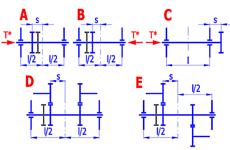
l, s .... picture
dsh ... shaft diameter
fma ... mesh misalignment. It is possible to use several
methods (calculation, measurement, estimation). Used formula:
fma = (fHb12 + fHb22)0.5
.
a) KHb = Acoef * (2 * Fby * cgb
/ (Fm / b))0.5 ...... [ Fby
* cgb / (2 * Fm / b) >= 1.0;
KHb > 1.0 ]
b) KHb = Acoef * (1 + Fby * cgb
/ (2 * Fm / b)) ...... [ Fby
* cgb / (2 * Fm / b) < 1.0;
KHb > 1.0 ]
Fm = Ft * KA * KV
Fby = Fb * 0.8
..... [Fb from ISO 1328]
cgb = 0.85 * cga
b ...... gear width
Acoef = 1.0 ..... Double-sided symmetrically supported gearing
Acoef = (0.9 + 0.15 * (b1 / d1)2 + 0.23 * (b1 / d1)3)
..... Double-sided non-symmetrically supported gearing
Acoef = (0.9 + (b1 / d1)2) ..... Overhung gearing
For the preliminary design is possible to use values from these graphs.
X Axis: Ratio gear width to gear diameter
Y Axis: Factor KHb ..... [min. value = 1.05]
Accuracy grade 7
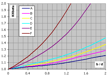
Not-hardended gears, VHV<370, design type A-F ... calculation paragraph [2.0]
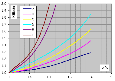
Hardended gears, VHV<=370, design type A-F ... calculation paragraph [2.0]
KFb = ( KHb )NF
NF = (b / h)2 / (1 + b / h + (b / h)2) ...... [když
b / h < 3; pak b / h = 3] ([if b / h < 3; then b / h = 3])
The smaller of the values b1/h1, b2/h2 is to be used as b/h.
KHa = KFa =
eg
/ 2 * (0.9 + 0.4 * (cga
* (fpb - ya)) / (FtH
/ b)) ...... [eg
<= 2.0]
KHa = KFa =
0.9 + 0.4 * (2.0 * (eg
- 1.0) / eg)0.5
* cga * (fpb
- ya) / (FtH /
b) ...... [eg
> 2.0]
Pro: (For:)
KHa >
eg
/ (
ea
* Ze2)
...... KHa =
eg
/ (
ea
* Ze2)
KHa <
1.0 ...... KHa
= 1.0
Pro: (For:)
KFa >
eg
/ (0.25 *
ea
+ 0.75) ...... KFa =
eg
/ (0.25 *
ea
+ 0.75)
KFa <
1.0 ...... KFa
= 1.0
fpb = fpt (ISO1328-1)
ya ... Material: St, St(cast),
V, V(cast), GGG(perl.), GGG(bai.), GTS(perl.)
ya = fpb * 160 /
σHlim [ v < 5m/s ]
ya
<= 12800 / σHlim [ 5m/s < v <= 10m/s ]
ya
<= 6400 / σHlim [ v > 10m/s ]
ya ... Material: GG,
GGG(ferr.)
ya = fpb 0.275
[ v < 5m/s ]
ya
<= 22 [ 5m/s < v <= 10m/s ]
ya
<= 11 [ v > 10m/s ]
ya ... Material:
Eh, IF, NT(nitr.), NV(nitr.), NV(nitrocar.)
ya = fpb 0.075
[ ya
<= 3 ]
This part of ISO 6336 specifies the fundamental formulae for use in the determination of the surface load capacity of cylindrical gears with involute external or internal teeth. It includes formulae for all influences on surface durability for which quantitative assessments can be made. lt applies primarily to oil-lubricated transmission, but can also be used to obtain approximate values for (slow-running) grease-lubricated transmissions, as long as sufficient lubricant is present in the mesh at all times.
Safety factor for surface durability (against pitting), SH
Calculate SH separately for pinion and wheel:
SH1,2 = σHG1,2 / σH1,2 > SHmin
σH1 = ZB * σH0 * (KA * KV * KHb
* KHa)0.5
σH2 = ZD * σH0 * (KA * KV * KHb
* KHa)0.5
The
nominal contact stress at the pitch point σH0
σH0 = ZH * ZE * Ze
* Zb * (Ft / (b * d1)
* (u + 1) / u)0.5
σHP = ZL * ZV * ZR * ZW * ZX * ZNT * σHlim / SHmin = σHG / SHmin
The pitting stress limit σHG
σHG = σHP * SHmin
ZH = (2 * cos(bb) * cos(awt) / (cos(at)2 * sin(awt)))0.5
M1 = tan(awt) /
((((da1 / db1)2 - 1.0)0.5 - 2 *
p / z1) * (((da2 / db2)2
- 1.0)0.5 - (ea
- 1.0) * 2 * p / z2))0.5
M2 = tan(awt) /
((((da2 / db2)2 - 1.0)0.5 - 2 *
p / z2) * (((da1 / db1)2
- 1.0)0.5 - (ea
- 1.0) * 2 * p / z1))0.5
Spur gears with, ea
> 1.0
ZB = 1.0 ... [ M1<= 1.0 ]
ZB = M1 .... [ M1 > 1.0 ]
ZD = 1.0 ... [ M2<= 1.0 ]
ZD = M2 .... [ M2 > 1.0 ]
Helical gears with, eb
>= 1.0
ZB = ZD = 1.0
Helical gears with, eb
< 1.0
ZB = M1 - eb
* (M1 - 1.0) ... [ ZB >= 0 ]
ZD = M2 - eb
* (M2 - 1.0) ... [ ZD >= 0 ]
(For internal gears, ZD shall be taken as equal to 1.0)
ZE = (p * ((1.0 - n12) / E1 + (1 - n22) / E2))-0.5
n1,2 ... Poisson's ratio
E1,2 ... modulus of elasticity
Ze = ((4.0 -
ea)
/ 3 * (1.0 - eb)
+ eb
/ ea)0.5
... [ 0 <= eb
< 1.0 ]
Ze = (1.0 /
ea)0.5
... [ eb
>= 1.0 ]
Zb = 1 / (cos(b))0.5
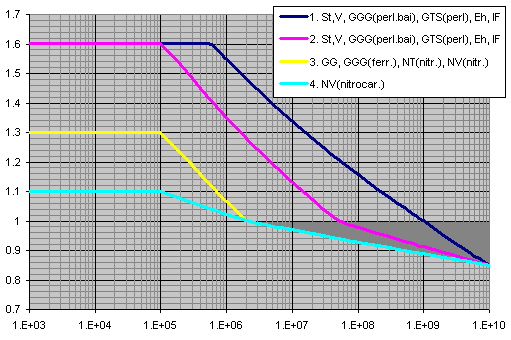
X axis ... number of cycles
Y axis ... ZNT
ZL = CZL + 4 * (1.0 - CZL) / (1.2 + 80 /
n50)2 = CZL
+ 4 * (1.0 - CZL) / (1.2 + 134 / n40)2
CZL = 0.83 ... [ σHlim < 850 ]
CZL = σHlim / 4375 + 0.6357 ... [
850 <= σHlim <= 1200 ]
CZL = 0.91 ... [ 1200 < σHlim ]
n50 (
n40) ... Nominal viscosity in 50°C (40°C) [mm2/s]
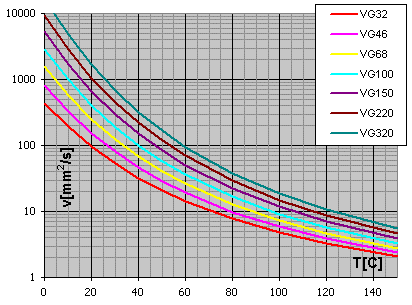
Diagram viscosity / temperature for viscosity index VI = 50
ZV = CZV + 2 * (1.0 - CZV) / (0.8 + 32 / v)0.5
CZV = CZL + 0.02
ZR = (3 / Rz10)CZR
CZR = 0.15 ... [ σHlim < 850 ]
CZR = 0.32 - 0.0002 * σHlim ... [
850 <= σHlim <= 1200 ]
CZR = 0.08 ... [ 1200 < σHlim ]
Rz10 = Rz * (10 / rred)(1/3)
rred = (r1
* r2) / (r1
+ r2)
r1,2 = 0.5 * db1,2 *
tan(awt)
The work hardening factor, ZW takes account of the increase in the surface durability due to meshing a steel wheel (structural steel, through-hardened steel) with a hardened or substantially harder pinion with smooth tooth flanks.
Pinion Surface-hardened, Gear through-hardened
ZW = 1.2 * (3 / RzH)0.15 ... [ HB < 130 ]
ZW = (1.2 - (HB - 130) / 1700) * (3 / RzH)0.15
... [ 130 <= HB <= 470 ]
ZW = (3 / RzH)0.15 ... [ HB > 470 ]
ZW for static stress
ZW = 1.05 ... [ HB < 130 ]
ZW = 1.05 - (HB - 130) / 680 ... [ 130 <= HB <= 470 ]
ZW = 1.0 ... [ HB > 470 ]
RzH = Rz1 * (10 / rred)0.33
* (Rz1 / Rz2)0.66) / (
n40 * v / 1500)0.33)
... [ 3 <= RzH <=16 ]
Through-hardened pinion and gear
ZW = 1.0 ... [ HB1/HB2 < 1.2 ]
ZW = 1.0 + A * (u - 1.0) ... [ 1.2 <= HB1/HB2
<= 1.7 ]
ZW = 1.0 + 0.00698 * (u - 1.0) ... [ 1.7 < HB1/HB2
]
A = 0.00898 * HB1/HB2 - 0.00829
ZW for static stress
ZW = 1.0
This part of ISO 6336 specifies the fundamental formulae for use in tooth bending stress calculations for involute external or internal spur and helical gears with a rim thickness sR > 0.5 * ht for external gears and sR >1.75 * mn for internal gears.
Safety factor for bending strength (safety against tooth breakage), SF
Calculate SF separately for pinion and wheel:
SF1,2 = σFG1,2 / σF1,2 >= SFmin
σF = σF0 * KA * KV * KFb * KFa
The nominal tooth root
stress σF0
σF0 = Ft / (b * mn) * YF * YS
* Yb * YB * YDT
σFP = σFlim * YST * YNT * YdrelT * YRrelT * YX / SFmin = σFG / SFmin
Tooth root stress limit σFG
σFG = σFP * SFmin
YF = (6 * hFe / mn * cos(aFen)) / ((sFn / mn)2 * cos(an))
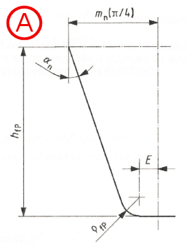
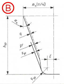
Dimensions and basic rack profile of the teeth (finished profile)
A...without undercut
B...with undercut
auxiliary values
E = p / 4 * mn - hfP
* tan(an) + spr / cos(an)
- (1 - sin(an) * rfP
/ cos(an)
spr = pr - q
spr = 0 when gears are not undercut
rfPv = rfP
... external gears
rfPv = rfP
+ mn * (x0 + hfp/mn - rfP/mn)1.95
/ (3.156 * 1.036z0) ... internal gears
x0 ... the pinion-cutter shift coefficient
z0 ... the number of teeth of the pinion cutter
G = rfPv / mn - hfP
/ mn + x
H = 2 / zn * (p / 2 - E / mn)
- T
T = p / 3 ... external gears
T = p / 6 ... internal gears
q = 2 * G / zn * tan(q)
- H
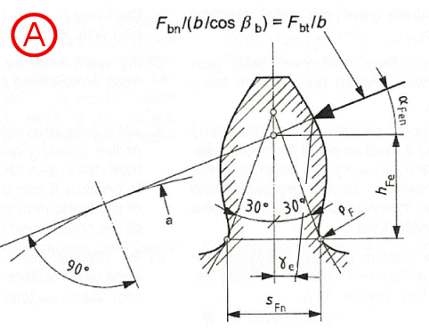
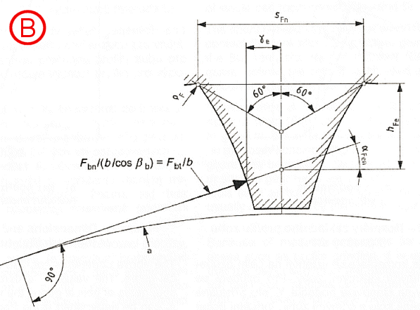
Determination of normal chordal dimensions of tooth root critical section for
Method B
A...external gears
B...internal gears
Tooth root normal chord sFn
sFn / mn = zn * sin(p/3 - q) + (3)0.5 * (G / cos(q)
- rfPv / mn) ...
external gears
sFn / mn = zn * sin(p/6 - q)
+ (G / cos(q)
- rfPv / mn) ...
internal gears
Radius of root fillet rF
rF / mn
= rfPv / mn + 2 * G2
/ (cos(q) * (zn * cos(q)2
- 2 * G))
Bending moment arm hFe
hFe / mn = 0.5 * ((cos(ge)
- sin(ge) * tan(aFen))
* den / mn - zn * cos(p/3
- q) - G / cos(q)
+ rfPv / mn)) ...
external gears
hFe / mn = 0.5 * ((cos(ge) - sin(ge) * tan(aFen)) * den / mn - zn * cos(p/6 - q) - (3)0.5 * (G / cos(q) - rfPv / mn))) ... internal gears
Parameters of virtual gears
bb = arcsin(sin(b)
* cos(an))
zn = z / (cos(bb))3
ean=
ea / (cos(bb))2
dn = mn * zn
pbn = p * mn *
cos(an)
dbn = dn * cos(an)
dan = dn + da - d
den = 2 * z / abs(z) * ((((dan / 2)2 - (dbn
/ 2)2)0.5 - p * d *
cos(b) * cos(an)
* (ean - 1) / abs(z))2
+ (dbn / 2)2)0.5
*The number of teeth z is positive for external gears and negative for internal gears
aen = arccos(dbn /
den)
ge = (0.5 * p
+ tan(an) * x) / zn +
inv(an) - inv(aen)
aFen = aen
- ge
The stress correction factor YS is used to convert the nominal
tooth root stress to local tooth root stress.
YS = (1.2 + 0.13 * L) * qs(1 / (1.21 + 2.3 / L))
L = SFn / hFe
qs = SFn / (2 * rF)
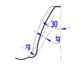
YSg = 1.3 * YS / (1.3 - 0.6 * (tg / rg)0.5) ... [ (tg / rg)0.5 < 2.0 ]
Yb = 1 - eb * b / 120 ... [if b > 30; b = 30]
external gears
YB = 1.0 ... [sR / ht >= 1.2]
YB = 1.15 * ln(8.324 * mn / sR) ... [0.5 < sR
/ ht < 1.2]
internal gears
YB = 1.0 ... [sR / mn >= 3.5]
YB = 1.6 * ln(2.242 * ht / sR) ... [1.75 < sR
/ mn < 3.5]
YDT = 1.0 ... [ean
<= 2.05] or [accuracy grade > 4]
YDT = -0.666 * ean
+ 2.366 ... [2.05 < ean
<= 2.5] and [accuracy grade <= 4]
YDT = 0.7 ... [ean
> 2.5] and [accuracy grade <= 4]
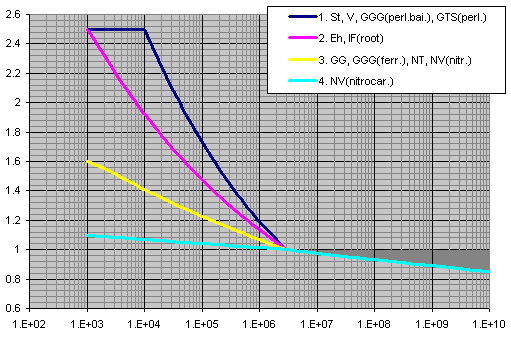
X axis ... number of cycles
Y axis ... YNT
YdrelT = Yd
/ YdT = (1 + (r'
* c*)0.5)
/ (1 + (r'
* cT*)0.5)
c* =
cP*
* (1 + 2 * qs)
cP*
= 1 / 5 = 0.2
cT*
= cP*
* (1 + 2 * 2.5)
Material: GG [σB=150MPa], GG, GGG(ferr.)[σB=300MPa]
r'
= 0.31
Material: NT, NV
r'
= 0.1005
Material: St, V, GTS, GGG(perl.), GGG(bai.)
r'
=
MAX(MIN(13100 / Rp0.2(2.1) - (MAX(600;Rp0.2)-600)(0.35)
/ 1600;0.32);0.0014)
Material: Eh, IF(root)
r'
= 0.003
Material: St, V, GGG(perl.), GGG(bai.)
YdrelT = (1 + 0.82 * (YS
- 1) * (300 / σ0.2)(1/4)) / (1 + 0.82 * (300 / σ0.2)(1/4))
Material: Eh, IF, IF(root)
YdrelT = 0.44 * YS +
0.12
Material: NT, NV
YdrelT = 0.20 * YS +
0.60
Material: GTS
YdrelT = 0.075 * YS +
0.85
Material: GG, GGG(ferr.)
YdrelT = 1.0
Rz < 1 mm
Material: V, GGG(perl.), GGG(bai.), Eh, IF
YRrelT = 1.12
Material: St
YRrelT = 1.07
Material: GG, GGG(ferr.), NT, NV
YRrelT = 1.025
1mm < Rz < 40 mm
Material: V, GGG(perl.), GGG(bai.), Eh, IF
YRrelT = 1.674 - 0.529 * (Rz + 1)0.1
Material: St
YRrelT = 5.306 - 4.203 * (Rz + 1)0.01
Material: GG, GGG(ferr.), NT, NV
YRrelT = 4.299 - 3.256 * (Rz + 1)0.0058
YRrelT = 1.0
YX = 1.0 ... All materials for static stress
YX ... Material: St, St(cast),
V, V(cast), GGG(perl.), GGG(bai.), GTS(perl.)
YX = 1.0
... [ mn <= 5 ]
YX = 1.03 - 0.006 * mn
... [ 5 < mn < 30 ]
YX = 0.85 ... [ mn >=
30 ]
YX ... Material:
Eh, IF(root), NT, NV, NT(nitr.), NV(nitr.), NV(nitrocar.)
YX = 1.0
... [ mn <= 5 ]
YX = 1.05 - 0.01 * mn
... [ 5 < mn < 25 ]
YX = 0.80 ... [ mn >=
25 ]
YX ... Material: GG,
GGG(ferr.)
YX = 1.0
... [ mn <= 5 ]
YX = 1.075 - 0.015 * mn
... [ 5 < mn < 25 ]
YX = 0.70 ... [ mn >=
25 ]
This part of ISO 6336 describes contact and tooth-root stresses, and gives numerical values for both limit stress numbers. It specifies requirements for material quality and heat treatment and comments on their influences on both limit stress numbers.
The allowable stress numbers, σH lim, and the nominal stress numbers, σF lim, can be calculated by the following equation:
a) σHlim = A * x + B
b) σFlim = A * x + B
where x is the surface hardness HBW or HV and A, B are constants
The three material quality grades ML, MQ and ME, stand in relationship to
- ML stands for modest demands on the material quality and on the material heat
treatment process during gear manufacture.
- MQ stands for requirements that can be met by experienced manufacturers at
moderate cost.
- ME represents requirements that must be realized when a high degree of
operating reliability is required
In this calculation, except σHlim and σFlim, are proposed other material
parameters that are necessary for calculating the gearing. The values of Ro, E
and Poisson constant are commonly available. For the proposal of the tensile strength Rm
and yield strength Rp0.2 was used information from the ISO 1265 and specialized
literature. Parameters for the time-strength curves were obtained from ISO6336-2
and 3. These curves can be seen in a small graph in the calculation.
All calculated values are design and based on empirical experience. The exact
values for a concrete material you can obtain from your manufacturer or from
material tests.
Values HB for HB<=450 steel ball, HB>450 carbide ball
Values HB used recalculation HB=HV-HV/20
Values HRC used recalculation HRC=(100*HV-14500)/(HV+223)
Kv = (C / (C + vt))−B
C = 50 + 56 * (1.0 − B) ... [ 6 ≤ Av ≤ 12 ]
B = 0.25 * (Av − 5.0)0.667
vt max = [C + (14 − Av)]2
The empirical guidance values from table B.1 ISO 6336-6 are used.
Cp = (1 / p
* (((1 - mP2)
/ EP) + ((1 - mG2) /
EG)))0.5 ... [lb/in2]0.5
mP and mG
is Poisson’s ratio for pinion and gear, respectively; EP and EG is
modulus of elasticity for pinion and gear [lb/in2].
Cf = 1.0
Through hardened gears
CH = 1.0 + A * (mG - 1.0)
A = 0.00898 *(HBP / HBG) - 0.00829
HBP is pinion Brinell hardness number [HB]; HBG is gear Brinell hardness
number,[HB].
This equation is valid for the range 1.2 ≤ HBP / HBG ≤ 1.7 For HBP / HBG < 1.2,
A = 0.0 HBP / HBG > 1.7, A = 0.00698
Surface hardened/through hardened values
CH = 1.0 + B * (450 - HBG)
B = 0.00075 * (2.71828)-0.0112 * (fp)
fp is surface finish of pinion, microinches, Ra
if fp>64 ... CH = 1.0
Km = f (Cmf, Cmt)
Km = Cmf
Cmf = 1.0 + Cmc * (Cpf *
Cpm + Cma * Ce)
Cmc is 1.0 for gear with unmodified leads; Cmc is 0.8 for gear with leads
properly modified by crowning or lead correction.
Cpf = F / (10 * d) − 0.025 ... [F<=1.0]
Cpf = F / (10 * d) − 0.0375 + 0.0125 * F ... [1.0<F<=17.0]
Cpf = F / (10 * d) − 0.1109 + 0.0207 * F − 0.000228 * F2 ...
[17.0<F<=40.0]
Cpm = 1.0 ... [S1 / S < 0.175]
Cpm = 1.1 ... [S1 / S >= 0.175]
Cma = A + B * F + C * F2
| A | B | C | |
| 1…Open gearing | 0.247 | 0.0167 | -0.0000765 |
| 2…Commercial enclosed gearboxes | 0.127 | 0.0158 | -0.0001093 |
| 3…Precision enclosed gearbox | 0.0675 | 0.0128 | -0.0000926 |
| 4…Extra precision enclosed gearbox | 0.038 | 0.0102 | -0.0000822 |
Ce = 0.8 ... [gearing is adjusted at assembly; gearing is
improved by lapping]
Ce = 1.0 ... [for all other conditions]
KR = 1.50 [Fewer than one failure in 10 000]
KR = 1.25 [Fewer than one failure in 1000]
KR = 1.00 [Fewer than one failure in 100]
KR = 0.85 [Fewer than one failure in 10]
KR = 0.70 [Fewer than one failure in 2]
KB = 1.6 * ln(2.242 / mB) ... [for mB<1.2]
KB = 1.0 ... [for mB>=1.2]
mB = tR / ht
tR is gear rimthickness below the tooth root
[in]; ht is gear
tooth whole depth [in]
The contact stress number formula for gear teeth is:
sc = Cp (Wt * Ko * Kv * Ks * Km * Cf / (d * F * I))0.5
Allowable contact stress number
The relation of calculated contact stress number to allowable contact stress
number is:
sc ≤ (sac * ZN * CH) / (KT * SH * KR)
Pitting resistance power rating
The pitting resistance power rating is:
Pac = (p * np * F / 396 000) * I / (Ko * Kv * Ks * Km * Cf) * ((d * sac * ZN CH) / (Cp * SH * KT * KR))2
SH = sac / sc * (ZN * CH) / (KT * KR)
The fundamental formula for bending stress number in a gear tooth is:
st = Wt * Ko * Kv * Ks * (Pd * Km * KB / (F * J))
Allowable bending stress number
The relation of calculated bending stress number to allowable bending stress
number is:
st ≤ (sat * YN) / (SF * KT * KR)
Bending strength power rating
The bending strength power rating is:
Pat = (p * np * F / 396 000) * (F * J) / (Ko * Kv * Pd * Ks * Km * KB) * (sat * YN) / (SF * KT * KR)
SF = sat / st * YN / (KT * KR)
Transmitted tangential load
Wt = 33000 * P / vt = 2 * T / d = 396000 * P / (p
* np * d)
P is transmitted power [hp];
T is transmitted pinion torque [lb*in];
vt is pitch line velocity at operating pitch diameter,
[ft/min]
vt = p
* np * d / 12
This part of ANSI / AGMA 2001-D04 describes the allowable stress numbers sac and sat, for pitting resistance and bending strength.
Allowable stress numbers in this standard are determined or estimated from
laboratory tests and accumulated field experiences. They
are based on unity overload factor, 10 million stress cycles, unidirectional
loading and 99 percent reliability. For service life other than 10
million cycles, the allowable stress numbers are adjusted by the use of stress
cycle factors YN and ZN
The allowable stress numbers sac and sat can be calculated by the following equation:
a) sac = A * x + B
b) sat = A * x + B
where x is the surface hardness HBW and A, B are constants
These requirements are specified in this standard and are divided in three material quality grades 1,2 an 3.
In this calculation, except sac and sat, are proposed other material parameters that are necessary for calculating the gearing. The values of p, E and Poisson constant are commonly available. For the proposal of the tensile strength Rm and yield strength Rp0.2 was used information from the ISO 1265 and specialized literature. All calculated values are design and based on empirical experience. The exact values for a concrete material you can obtain from your manufacturer or from material tests.
Values HB for HB<=450 steel ball, HB>450 carbide ball
Values HB used recalculation HB=HV-HV/20
Values HRC used recalculation HRC=(100*HV-14500)/(HV+223)
^