This document can be used for the selection, calculation and check of rolling bearings of the company SKF. The programme provides solutions to the following tasks:
In addition to the above given basic calculations, the document also includes several other auxiliary calculations (e.g. a calculation of lubricant operational viscosity, calculation of mean loads for bearings loaded by variable loads, calculation of permitted bearing speed, etc.).
The programme uses data, procedures, algorithms and other information from specialised literature, catalogues of rolling bearings SKF, ISO, ANSI, SAE standards and other sources.
Related standards: ISO 15, ISO 76, ISO 104, ISO 281, ISO 355, ISO 1132, ISO 5593, ISO 5753, ISO 3448, ISO 15312, DIN 615, DIN 620, DIN 625, DIN 628, DIN 630, DIN 635, DIN 711, DIN 715, DIN 720, DIN 722, DIN 728, BS 290, BS 292, BS 3134
User interface.
Download.
Purchase, Price list.
Information on the syntax and control of the calculation can be found in the document "Control, structure and syntax of calculations".
Information on the purpose, use and control of the paragraph "Information on the project" can be found in the document "Information on the project".
Rolling bearings are produced in a wide scope of different designs and sizes. They usually consist of two rings, rolling elements and a cage. The bearings are divided into several basic types according to their inner design, the shape of rolling bodies and directions of the forces that can be retained. A comparison of individual types of rolling bearings can be found in the document "Selection of a rolling bearing".
Basic types of rolling bearings are internationally standardized. Within the scope of each type the bearings are produced in various designs whose properties may differ from the basic design. Detailed technical parameters of rolling bearings are given in catalogues of individual producers.
Selection of suitable dimensions of the bearing is determined by the amount, direction and type of load on the bearing and its speed. Depending on the type of load on the bearing in operation, the bearings may be divided into two groups for calculation purposes:
The life of a rolling bearing is understood as the number of its revolutions (or the period of its operation at the given speed) to the moment when the first traces of fatigue of material on rolling elements or orbital paths appear. Practical tests show that the life of identical bearings differs under the same operational conditions. In order to assess the service life of bearings, the so-called basic life measurement has been introduced.
The basic life of rolling bearings is the life that is achieved or exceeded by 90% of identical bearings under the same operational conditions provided that commonly used materials were used, usual production quality achieved and bearings are operated under normal operational conditions. The basic life is defined by the equation:

where:
C ... basic dynamic bearing load rating [N, lb]
P ... equivalent bearing dynamic load [N, lb]
n ... bearing speed [1/min]
p ... exponent (p=3 for ball bearings, p=10/3 for other bearings)
Basic dynamic load rating of the bearing is defined as a constant non-variable load at which the bearing reaches the basic life of 1 million revolutions. Values of dynamic loading capacities are given for each bearing in the respective catalogue.
Equivalent dynamic load rating of the bearing is defined exclusively as a radial load (with radial bearings) or axial load (with axial bearings), at which all bearings of the same type show the same life as reached under conditions of a real load. The amount of the equivalent load is described in the relation:
![]()
where:
Fr ... radial component of the
real load [N, lb]
Fa ... axial component of the real load [N, lb]
X ... coefficient of radial dynamic load
Y ... coefficient of axial dynamic load
Values of the coefficients X, Y depend on the type, design and size of the bearing; with some types of bearings, also on the direction and amount of the real load. These values are given for each bearing in the respective catalogue.
The basic life assesses the life of the rolling bearing only in view of loads acting on it and does not take into account any other effects such as operational conditions, production quality or properties of the materials used. Efforts to enhance the quality and reliability of the designs lead to the requirement to calculate the life of the bearing more precisely and therefore the standard ISO has introduced a modified equation of the life:
![]()
where:
a1 ... coefficient of the life for the required reliability (see the
table below)
a2 ... coefficient of the life for the given material properties and
level of production technology
a3 ... coefficient of the life for the given operational conditions
| Reliability [%] | 90 | 95 | 96 | 97 | 98 | 99 |
| a1 | 1.00 | 0.62 | 0.53 | 0.44 | 0.33 | 0.21 |
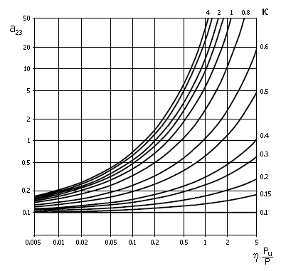
Due to the mutual dependence of coefficients a2 and a3 producers of bearings usually introduce the common value a23. The value of this coefficient will depend, above all, on the quality of lubrication and according to recommendations in ISO 281 it is determined in dependence on the type of bearing using the respective diagram (see the picture).
where:
k ... viscosity ratio
(gives the rate between operational and rated lubricant viscosity
k=n/n1
- see the chapter on lubrication of bearings)
h ... coefficient of
the level of contamination of the lubricant (see par. [3.10])
P .... equivalent dynamic load
PU ... fatigue load limit (given for each bearing in the respective
catalogue)
In case the producer does not give these values of limit fatigue loads with the bearings, you can use approximate values in calculations as given in the following theoretical relations:

... for ball bearings

... for self-aligning ball bearings

... for other bearings
The external system of forces acting on the seating must be distributed with a calculation of the bearing into the forces acting in the radial and axial directions. The intersection of normal lines at contact points of rolling bodies and orbital paths with the axis of the bearing (see the illustration) is considered the centre of the acting forces.

Additional dynamic forces (vibrations and surges) that increase loading on bearings usually occur with machines in operation. These additional forces cannot usually be calculated or measured precisely. Their effects are therefore expressed by various empirical factors that multiply the calculated radial and axial forces. In case of toothed gears, the amount of these additional forces depends on the accuracy of toothing and in case of machines connected to belt drives, on the type of belt and its prestressing. Values of the respective coefficients are usually given in documents of producers of belts and gears, orientation values can be found in par. [1.15].
Fluctuating load.
The above-mentioned calculations of the life of rolling bearings are
based on the presumption that the bearing is operated under constant
non-variable operational conditions. However, in practice this presumption is
often not fulfilled. In applications where the amount of direction of the load
or speed, temperature, conditions of lubrication or level of contaminations
varies over the course of time, it is not possible to determine the bearing life
directly. In such cases it is necessary to divide the bearing working cycle into
several time periods in which the operational conditions are approximately
constant (see the picture).
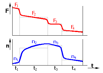
It is necessary to calculate the bearing life separately for each such period. The total bearing life can be determined using the relation

where:
Lmhi ... partial bearing life for individual time periods with
constant operational conditions [h]
ti ....... time portions of individual periods in the bearing’s total
working cycle [%]
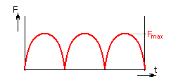
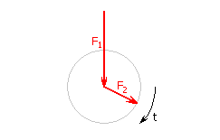
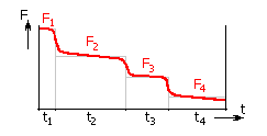
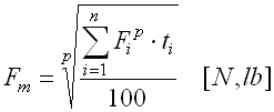
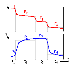
In an effort to design a bearing quickly, practical procedures use a simplified way of calculation of the bearing life for some types of loads. In this calculation the external load of the bearing is replaced by a virtual mean permanent load that shows the same effects on the bearing as an actually acting variable load. The procedures for determination of the mean load for some common types of loads are given in the table.
| Fluctuating load with linear change of the amount, at constant speed | |
|
|
 |
| Fluctuating load with sinusoidal course, at constant speed | |
 |
|
| Rotating load, at constant speed | |
 |
|
| Fluctuating load, at constant speed | |
 |
 |
| Fluctuating load, at variable speed | |
 |
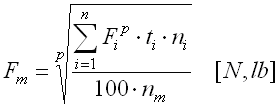 where mean speed:
|
| Oscillating motion | |
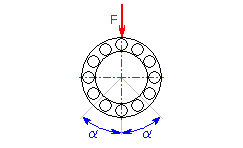 |
Oscillating motion is replaced by virtual
rotation at the speed equal to the frequency of oscillation:
|
| where: Fi ... partial non-variable load [N, lb] ni ... constant speed during acting of partial loads [1/min] ti ... time portions of acting of partial loads in the bearing’s total working cycle [%] p ... exponent (p=3 for ball bearings, p=10/3 for other bearings) |
|
Commonly produced and delivered rolling bearings are designed for operational temperatures up to 120 °C (100 °C for sealed bearings). In case of use of a bearing at permanently higher temperatures it is necessary to modify it during production to ensure its dimensional stability under operation. Bearings for use at high temperatures are produced with thermal treatment, usually with greater clearances and a differently designed cage, possibly with the use of special materials.
Requirements for the use, production and delivery of stabilized bearings must usually be consulted with the producer, where you can find detailed technical parameters of the bearing. For the purposes of preliminary designs it is possible to use the following orientation table.
| Limiting temperature | 150 | 200 | 250 | 300 | 350 |
| Supplementary designation | S0 | S1 | S2 | S3 | S4 |
| Load rating [%] | 90 - 100 | 75 - 90 | 60 -75 | 50 - 60 | 45 - 50 |
A bearing at static load is loaded by forces at standstill, at very slow speed or slow swinging movements. The load rating of the bearing is determined by permissible permanent deformations of orbital paths and rolling bodies. The coefficient of safety s0 gives the standard of safety of static-loaded rolling bearings and is defined by the following relation:

where:
C0 ... basic bearing static load rating [N, lb]
P0 ... equivalent bearing static load rating [N, lb]
Basic static load rating of the bearing is defined as the external load that causes a permanent deformation of 0.0001 of the diameter of the rolling body at the contact point of the most loaded rolling body. This permanent deformation usually has no adverse effects on the bearing function. Values of static load ratings are given for each bearing in the respective catalogues.
Equivalent static load rating of the bearing is defined exclusively as radial load (with radial bearings) and axial load (with axial bearings) respectively, which causes a permanent deformation in the bearing and this deformation is of the same size as under actual conditions of loading. The amount of the equivalent load is described by the relation
![]()
where:
Fr ... radial component of the
real load [N, lb]
Fa ... axial component of the real load [N, lb]
X0 ... coefficient of radial static load
Y0 ... coefficient of axial static load
Values of the coefficient X0,Y0 depend on the type, design and size of the bearing. These values are given for each bearing in the respective catalogue.
The friction moment of rolling bearings depends on many factors (design of the bearing, method of lubrication, speed, etc.) and it is very difficult to determine exactly. Practical calculations therefore use a simplified model with the use of an estimated coefficient of friction. Under the assumption of normal operational conditions and good lubrication an approximate friction moment can be calculated with rolling bearings operated at mean speed using the equation

where:
P ... equivalent dynamic load of the bearing [N]
d ... diameter of the bearing hole [mm]
f ... coefficient of friction (depending on the type of bearing,
f=<0.0010...0.0050>)
In case of sealed bearings the moment from the friction sealing must be added to the calculated friction moment. The resulting friction moment further determines the power loss NR that is equal to the heat produced in the seating:

where:
n ... speed of the bearing [1/min]
In case the shaft is seated in two single row angular contact ball bearings or in two tapered roller bearings, a mutual inner axial force is produced with radial load in the bearings. This force will naturally affect the bearing load rating and therefore it must be included in the calculation. The amount of the axial load of one bearing depends on the contact angle and arrangement of both bearings, on the amount of radial forces FrA, FrB and on the direction and amount of the external axial force Ka.

The calculation must also consider the seating as a unit and both bearings must be designed at the same time.
Higher speeds create a danger of rolling elements slipping between the orbital paths of the rings with unloaded bearings due to centrifugal forces. This may adversely affect wear of the bearing and thus reduce its life. The bearing should be loaded by a certain minimum force under operation to ensure correct rolling. The amount and size of this force depends on the type, design and size of bearing and operational conditions. The relations for determining the minimum load are usually given in catalogues of individual producers.
The heat that is produced by friction must be dissipated to achieve thermal balance. The operational temperature depends on many factors; its calculation is very complicated and leads to a system of non-linear equations. The following relation can be used for fast orientation:

where:
t0 ..... ambient temperature [°C]
NR .... power loss [W]
WS ... coefficient of cooling [W/°C]
The coefficient of cooling gives the amount of heat being dissipated into the ambient air at a temperature drop of 1 °C. For bearings seated in frame machines it can be determined approximately using the relation
![]()
where:
D ... outer diameter of the bearing [mm]
v ... velocity of air [m/s] (v~1-2 for bearings
inside the buildings, v~2-4 for bearings in the open
air)
The speed of rolling bearings cannot be increased without any limitation. Centrifugal forces of the bearing increase its loading, inaccuracy of its run causes vibrations and friction in the bearing causes warming. Limit speed depends on the type, design and size of bearing, its accuracy, and the design of the cage, inner clearances and operational conditions in its seating and, above all, the highest permissible temperature of the lubricant.
No specific and generally applicable limit of permissible speed can be determined exactly for rolling bearings. Producers give in their dimensional tables guide values of limit speeds for individual bearings for the purposes of fast orientation. These values are based on practical experience and are applicable for bearings with normal clearances and produced at normal levels of accuracy provided that they are operated under normal conditions and with usual cooling. The given limit speeds can be exceeded in certain individual cases, however, it is advisable to consult this with the producer.
In addition to limit speeds, some producers also state in their catalogues of rolling bearings values of so-called thermal reference speeds. The reference speed gives the limit permissible speed of the bearing under exactly defined conditions and serves as an initial value for determining the permitted speed of the bearing for the given operational conditions.
![]()
where:
nr ... reference speed [1/min]
fp ... adjustment factor for the given type, size and load of bearing
fv ... adjustment factor for the chosen conditions of lubrication
The method of determining adjustment factors is described in catalogues of individual producers or in ISO 15312. The reference speeds given in the dimensional tables are defined for the following operational conditions:
The reason for lubricating rolling bearings is to create a carrying lubrication film on contacts between rolling bodies with orbital paths of the rings. In addition, the lubricant protects the bearing from corrosion, improves its sealing, exhibits cooling effects and lubricates the surfaces of the bearing with sliding friction.
Rolling bearings can be lubricated by plastic or liquid lubricants. Selection of a suitable lubricant is determined, above all, by the speed, operational temperature, position of the shafts, general concept of seating and economy of operation. If permitted by operational conditions, greases are preferred with rolling bearings.
Grease lubrication.
Grease lubrication is preferential particularly as regards easy operation, economy and sealing of bearings against dirt and moisture. It enables a simple arrangement of seating and is better suited for high and surge loading. Greases must show good lubrication capability and high chemical, thermal and mechanical stability. The market offers a wide range of suitable greases. In addition, most producers of rolling bearings offer their own ranges of lubricants.
| Design. | Description | Viscosity [mm2/s] | Temperature [°C] | |
| 40 °C | 100 °C | |||
| LGMT2 | All purpose industrial and automotive | 110 | 11 | -30 ... 120 |
| LGMT3 | All purpose industrial and automotive | 120 | 12 | -30 ... 120 |
| LGEP2 | Extreme pressure, high load | 200 | 16 | -20 ... 110 |
| LGLT2 | Low load and temperature, high speed | 15 | 3.7 | -55 ... 100 |
| LGHP2 | High performance and high temperature | 96 | 10.5 | -40 ... 150 |
| LGFP2 | Food compatible | 130 | 7.3 | -20 ... 110 |
| LGGB2 | Biodegradable and low toxicity | 110 | 13 | -40 ... 120 |
| LGLC2 | Low temperature and high speed | 24 | 4.7 | -40 ... 120 |
| LGWA2 | Wide temperature range | 185 | 15 | -30 ... 140 |
| LGHB2 | High viscosity and high temperature | 450 | 26.5 | -20 ... 150 |
| LGET2 | Extreme temperature | 400 | 38 | -40 ... 260 |
| LGEM2 | High viscosity | 500 | 32 | -20 ... 120 |
| LGEV2 | Extreme high viscosity | 1000 | 58 | -10 ... 120 |
| LGWM1 | Extreme pressure, low temperature | 200 | 16 | -30 ... 110 |
Grease has a limited life in the bearing. The reason is its leakage from the bearing and impairment of its properties over the course of time. Therefore, it is necessary to refill or replace the lubricant at certain time intervals. The refill intervals will depend on the type and size of bearing and operational conditions. The recommended refill periods are given for individual bearings in catalogues of the producers
Oil lubrication.
Lubrication of rolling bearings by oil is not so good and is usually used only in the following cases:
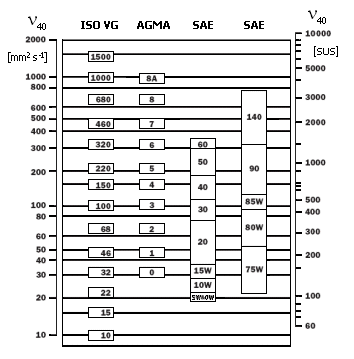
Depending on the operational conditions and desired design of seating several different types of oil lubrication of rolling bearings are used (oil bath, circulation of oil, spraying of oil, oil mist). Bearings are usually lubricated by mineral oils. Kinematic viscosity is the decisive property of oil; it decreases with increasing temperature. Practical experience shows that in the case of common seating the viscosity of oil should not drop below 12 mm2/s at operational temperatures. The rated viscosity that is determined in dependence on the mean diameter and speed of the bearing is the guiding factor for the selection of an oil with suitable operational viscosity.
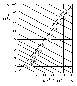
The qualitative standard of lubrication of rolling bearings is given in the viscosity ratio:

where:
n .... viscosity of the lubricant at operational temperatures [mm2/s]
n1 ... rated
viscosity [mm2/s]
For the viscosity ratio k<1 it is recommended to use a high-pressure oil with EP additives. Very long fatigue life can be achieved at k=3..4.
Accuracy of rolling bearings is understood as accuracy of their dimensions, shape and run (radial and axial run-out of the rings). Bearings are commonly produced at normal accuracy, which is not marked in the name of the bearing. Accuracy of bearings is standardized internationally, and markings of individual levels of accuracy can be found in the table:
| Standard | Accuracy class | ||||
| GB | G | E | D | C | B |
| ISO | Normal | Class6 | Class5 | Class4 | Class2 |
| ANSI | ABEC-1 | ABEC-3 | ABEC-5 | ABEC-7 | ABEC-9 |
| DIN | P0 | P6 | P5 | P4 | P2 |
| JIS | 0 | 6 | 5 | 4 | 2 |
Detailed information can be found in the respective catalogue of bearings.
Clearance of the bearing is the amount of free shift of one ring against the other from one margin position to the other. Correct run of the bearing is influenced, above all, by its radial clearance. Bearings with normal radial clearance, C0, which is not marked in the name of the bearing, are designed for normal operational conditions. Smaller clearances, C2, or greater clearances, C3, C4, C5, are chosen for significantly different operational conditions.
Detailed information can be found in the respective catalogue of bearings.
Selection of correctly matching bearing rings on the shaft and in the body has great importance as for the life of the rolling bearing. When selecting suitable tolerances, the following conditions are critical:
Orientation values for the selection of tolerances can be found in the following tables; exact data for individual types and sizes of bearings can be found in the respective catalogue.
| Operating conditions | Tolerance for bearings | ||
| ball | cylindrical and taper roller | spherical and toroidal roller | |
| Stationary inner ring load | |||
| Light and normal loads | g6 | ||
| Heavy and shock loads | h6 | ||
| Rotating inner ring load or direction of load indeterminate | |||
| Light and variable loads (P<0.07*C) | j6, k6 | j6, k6 | |
| Normal and heavy loads (P>0.07*C) | j5, k5, k6, m5, m6, n6 | k5, k6, m5, m6, n6, p6 | k5, k6, m5, m6, n6, p6, r6, r7 |
| Very heavy loads, shock loads (P>0.15*C) | n6, r6, p6 | n6, r6, p6 | |
| High mounting precision, light loads | h5, j5, k5 | j5, k5 | |
| Axial loads only | |||
| j6, js6 | j6, js6 | ||
| Operating conditions | Tolerance |
| Rotating outer ring load | |
| Very heavy loads, shock loads (P>0.15*C) | P7 |
| Normal and heavy loads (P>0.07*C) | N7 |
| Light and variable loads (P<0.07*C) | M7 |
| Direction of load indeterminate | |
| Heavy shock loads | M7 |
| Normal and heavy loads (P>0.07*C) | K7 |
| Light and normal loads (P<0.07*C) | J7 |
| Accurate or quiet running | |
| Ball bearings | J6 |
| Other bearings | JS5, K5, K6 |
| Stationary outer ring load | |
| All loads (P<0.15*C) | H7, H8 |
| Heat conduction through shaft | G7 |
| Bearing type | Tolerance | |
| shaft | housing | |
| Thrust ball, Cylindrical roller thrust bearings | j6, h6, h8 | H7, H8, H10 |
| Spherical roller thrust bearings | j6, js6, k6, m6, n6 | H7, K7, M7 |
Selection, calculation and check of a rolling bearing consist of the following steps:
In this paragraph perform selection of the desired type and design of bearing, define its loading and enter the desired physical properties of the bearing.
Select the desired calculation units in the selection list. When switching over the units, all values will be recalculated immediately.
Select the desired type of bearing in the selection list. A comparison of basic types of rolling bearings can be found in the document "Selection of a rolling bearing".
Within the range of each type, rolling bearings may be produced in a different design with some properties different from the basic design. In case the producer delivers various designs of the selected type [1.2], the programme offers the respective selection lists in rows [1.4 .. 1.6]. Set up the desired design of the bearing in these lists.
In this paragraph enter the radial and axial components of external loads of the bearing and its speed at constant non-variable operational conditions.
In this paragraph enter the required physical properties of the bearing. In case of bearings loaded dynamically their life will be critical; in case of bearings loaded statically their safety coefficient will be critical.
Enter the desired life of the bearing.
| Bearing life [hours] | Machine type |
| 300 - 3000 | Household machines, agricultural machines, instruments, technical equipment for medical use |
| 3000 - 8000 | Machines used for short periods or intermittently: electric hand tools, lifting tackle in workshops, construction equipment and machines |
| 8000 - 12000 | Machines used for short periods or intermittently where high operational reliability is required: lifts (elevators), cranes for packaged goods or slings of drums etc. |
| 10000 - 25000 | Machines for use 8 hours a day, but not always fully utilized: gear drives for general purposes, electric motors for industrial use, rotary crushers |
| 20000 - 30000 | Machines for use 8 hours a day and fully utilized: machine tools, woodworking machines, machines for the engineering industry, cranes for bulk materials, ventilator fans, conveyor belts, printing equipment, separators and centrifuges |
| 40000 - 50000 | Machines for continuous 24 hour use: rolling mill gear units, medium-sized electrical machinery, compressors, mine hoists, pumps, textile machinery |
| 30000 - 100000 | Wind energy machinery, this includes main shaft, yaw, pitching gearbox, generator bearings |
| 60000 - 100000 | Water works machinery, rotary furnaces, cable stranding machines, propulsion machinery for ocean-going vessels |
| > 100000 | Large electric machines, power generation plant, mine pumps, mine ventilator fans, tunnel shaft bearings for ocean-going vessels |
In case of wheeled vehicles, their life is usually given in millions of driven kilometres.
| Bearing life [106 km] | Type of vehicle |
| 0.1 - 0.3 | Road vehicles |
| 0.8 | Railway vehicles - freight wagons |
| 1.5 | Railway vehicles - underground carriages, tramway vehicles |
| 3 | Railway vehicles - passenger coaches |
| 3 - 5 | Railway vehicles - diesel and electric locomotives |
For recalculation use the following relation:

where:
n ... speed of the bearing [1/min]
D ... diameter of the vehicle wheel [m]
Enter the desired safety at static loading of the bearing.
| Operating conditions | Ball bearings | Other bearings |
| Rotation movement, only requirements regarding quiet running | ||
| Smooth operation, vibration-free | 0.5 | 1 |
| Normal operating conditions | 0.5 | 1 |
| Pronounced shock loads | 1.5 | 2.5 |
| Rotation movement, normal requirements regarding quiet running | ||
| Smooth operation, vibration-free | 1 | 1.5 |
| Normal operating conditions | 1 | 1.5 |
| Pronounced shock loads | 1.5 | 3 |
| Rotation movement, high requirements regarding quiet running | ||
| Smooth operation, vibration-free | 2 | 3 |
| Normal operating conditions | 2 | 3.5 |
| Pronounced shock loads | 2 | 4 |
| Non-rotating bearings | ||
| Smooth operation, vibration-free | 0.4 | 0.8 |
| Normal operating conditions | 0.5 | 1 |
| Pronounced shock loads | 1 | 2 |
| Oscillating motion | ||
| great oscillation amplitude with small frequency and with
approximately steady periodic loading |
1.5 | 2 |
| small oscillation amplitude with high frequency and with
shock uneven loading |
2 | 3 |
Note: In case of axial spherical roller bearings it is recommended to use the minimum value of the coefficient s0=4.
Additional dynamic forces (vibrations and surges) that increase loading on bearings usually occur with machines in operation. These additional forces cannot usually be calculated or measured precisely. Their effects are therefore expressed by various empirical factors that multiply the calculated radial and axial forces.
In this paragraph define the individual factor depending on the type of machine used. The resulting factor of additional forces is calculated additionally in [1.11].
In case of transmissions with toothed gears the amount of additional forces will depend on the accuracy of the toothing and machines connected to the transmission.
The factor of additional forces fk, resulting from inaccuracy of toothing, should be entered in row [1.19]. The recommended values for the selected type of toothing [1.18] are given in the green field.
The factor of additional forces from the connected machines fd should be entered in row [1.21]. The recommended values for the selected type of machine [1.20] are given in the green field.
In case of belt drives, the amount of additional forces will depend on the type of belt and its pre-stressing. The factor of additional forces fp should be entered in row [1.24]. Data on its amount are usually given in materials from the producers of the belts. If the data are not available, use the recommended values that are given for the selected type of belt [1.23] in the green field. Higher values in the given range should be used for short lengths of shafts, surge loads or large pre-stressing of belts.
This paragraph can be used for selection of a bearing of a suitable size. Dimensions of the bearing should be selected in par. [2.1]. Physical properties, dimensional and operational parameters of the selected bearing are calculated in par. [2.2] in real time.
In the selection list select a bearing with the desired dimensions.
Individual bearings are listed in ascending order according to inner diameter.
The table parameters of the bearing are arranged in columns in the following
order:
- Main dimensions of the bearing (inner and outer diameter, width of the
bearing)
- Basic dynamic and static load rating of the bearing (C, C0)
- Reference and limit speeds (nr, nmax)
- Marking of the bearing
The programme provides a function of automatic searching for a bearing of a suitable size to facilitate the design. After pressing the button "Find first" the programme finds the first bearing that meets the requirements for life and static safety as defined in par. [1.12]. In case some recommended values are exceeded with the proposed bearing or this bearing does not meet the desired requirements, use the button "Find next" to find another bearing.
When searching for a suitable bearing, the programme also checks any possible exceeding of the permitted load [2.9, 2.10]. In case the calculation cannot find a suitable bearing, select another type [1.2] or design of bearing [1.3] and repeat the calculation.
Basic parameters of the selected bearing are calculated additionally in this paragraph in real time. Physical properties and operational parameters of the bearing are given in the left part, its dimensions in the right part.
After unchecking the check box in this line, you can enter into the calculation your own values of the basic bearing capacity. In this way you may calculate the approximate comparison of the service life for an equivalent bearing supplied by another manufacturer.
Not all types of rolling bearings can carry combined loads. Some types are designed only for retaining radial forces, other types for axial forces; some types may carry only limited loads in the given direction. The recommended amounts of permitted loads are prescribed for the given types by producers and calculated additionally for the selected bearing in row [2.9] or [2.10] resp.
Reference value which is valid for given type and size of the bearing with the assumption of standard operating conditions, load P/C≈0.1 and good type of lubrication.
The adjusted life [3.12] and recommended amount of minimum load [3.6] are calculated additionally for the given operational parameters (lubrication) of the selected bearing in this paragraph.
In row [3.3] enter the kinematic viscosity of the lubricant used at the operating temperature. In case of plastic lubricants the kinematic viscosity of its basic oil component is given.
Practical experience shows that in the case of common seating the viscosity of oil should not drop below 12 mm2/s at operating temperatures. The rated viscosity [3.2] that is determined in dependence on the mean diameter and speed of the bearing is the guiding factor for the selection of an oil with suitable operating viscosity. The qualitative standard of lubrication of rolling bearings is given in the viscosity ratio [3.4]. For the viscosity ratio k<1 it is recommended to use a high-pressure oil with EP additives. Very long fatigue life can be achieved at k=3..4.
Higher speeds create a danger of rolling elements slipping between the orbital paths of the rings with unloaded bearings due to centrifugal forces. This may adversely affect wear of the bearing and thus reduce its life. The bearing should be loaded by a certain minimum force under operation to ensure correct rolling. The amount and size of this force depends on the type, design and size of bearing and operational conditions. The recommended amount of the minimum load is additionally calculated for the given bearing in row [3.6].
The basic life [2.5] assesses the life of the rolling bearing only in view of loads acting on it and does not take into account any other effects such as operational conditions, production quality or properties of the materials used. This paragraph includes the adjusted life of the selected bearing calculated for the given load, desired reliability and assumed operating viscosity and the level of contamination of the lubricant.
After unchecking the check box in this line, you can enter into the calculation your own value of the fatigue load limit. In this way you may calculate the approximate comparison of the service life for an equivalent bearing supplied by another manufacturer.
Select the desired reliability in the selection list.
The reliability gives the percentage share of bearings from a group of identical bearings working under the same operational conditions that reach the calculated operation life. The basic life of rolling bearings [2.5] is determined for a reliability of 90%.
In row [3.11] enter the factor of the level of contamination of the lubricant. Its amount varies in the interval <0..1>; the recommended values for the selected level of contamination [3.10] are given in the green field.
Level of contamination of the lubricant is divided into several levels:
This paragraph gives some auxiliary calculations for approximate determination of some operational parameters of rolling bearings (operating viscosity of the lubricant, length of relubrication intervals, desired oil flow, etc.).
This paragraph is designed to determine the approximate kinematic viscosity of the selected lubricant at the operating temperature [4.2]. The calculation is divided into two parts:
The desired oil flow [4.13] or the length of the relubrication interval [4.14] resp. are additionally calculated for the selected bearing [2.1] and the selected method of lubrication [4.12].
The necessary flow of oil for cooling the bearing with circulatory lubrication is determined for the given warming of the bearing (power loss [2.13]) in this row. The calculated oil flow is a theoretical table value that is determined for the difference in temperatures at the oil inlet and outlet, DT=10 °C.
The recommended length of the relubrication interval is determined for the given load and speed of the selected bearing. The given value is valid for loads C/P>4, normal lubrication conditions and operational temperature of the lubricant up to 70 °C (~160 °F). In case of higher temperatures the additional lubrication interval is shorter.
The permissible speed of the bearing is determined for the given load, method of lubrication [4.12] and viscosity of the lubricant [4.17] in this paragraph. The calculated value is for orientation purposes only and can be applied for a lubricant with reference viscosity n40 up to 460 [mm2/s], at normal cooling conditions, temperature of the lubricant 70 °C and ambient temperature 20 °C.
The used calculations of the life of rolling bearings are based on the presumption that the bearing is operated under constant non-variable operational conditions. However, in practice this presumption is often not fulfilled.
The auxiliary calculation in this paragraph is designed to determine the mean non-variable loading in applications where the bearing is exposed to a loading of a variable amount in a constant direction at a constant or variable speed.

When calculating the mean loading, proceed in the following steps:
In case the shaft is seated in two single row angular contact ball bearings or in two tapered roller bearings, a mutual inner axial force is produced with radial load in the bearings. This force will naturally affect the bearing load rating and therefore it must be included in the calculation. The amount of the axial load of one bearing depends on the contact angle and arrangement of both bearings, on the amount of radial forces FrA, FrB and on the direction and amount of the external axial force Ka.

The calculation must also consider the seating as a unit and both bearings must be designed at the same time. In case of the design of bearings, proceed in the following steps:
Information on options of 2D and 3D graphic outputs and information on cooperation with 2D and 3D CAD systems can be found in the document "Graphic output, CAD systems".
Information on setting of calculation parameters and setting of the language can be found in the document "Setting calculations, change the language".
General information on how to modify and extend calculation workbooks is mentioned in the document "Workbook (calculation) modifications".
^