The calculation is intended for the geometrical design and strength control of statically loaded welded connections of machine structures manufactured from carbon steels. The program enables you to design over 50 of the most common types of welded connections stressed by various combinations of load. The calculation deals with the following tasks:
Design of connections with butt welds.
Design of connections with plug and slot welds.
Design of connections with spot (resistance) welds.
Strength control of designed connections.
The program includes a table with approx. 700 carbon steels suitable for welding according to the material standards ANSI, EN, JIS, ISO, DIN, BS, NF, UNI, UNE, SIS, CSA, NBN, NP, NS, ON and CSN.
The program also includes a dimensional table of steel sections S, ST, W, WT, C, L according to ASTM/AISI/AISC and T, I, U, L sections according to DIN/EN/ISO.
The calculation is based on data, procedures and algorithms from specialized literature and standards AWS, AISC, ANSI, EN, ISO, DIN and others.
List of standards: prEN 1993-1-8, EN 10024, EN 10034, EN 10055, EN 10056, EN 10279, DS 952, DIN 15018, DIN 18800, DIN 1024, DIN 1025, DIN 1026, DIN 1028, DIN 1029, CSN 050120
![]()
User interface.
![]()
Download.
![]()
Purchase, Price list.
Information on the syntax and control of the calculation can be found in the document "Control, structure and syntax of calculations".
Information on the purpose, use and control of the paragraph "Information on the project" can be found in the document "Information on the project".
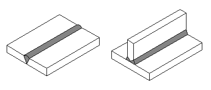
The welded connections are solid, non-detachable connections based on the principle of local melting of connected parts using heat or pressure. The joining of components proper may be achieved technically using two methods:
An optimum result of the welding process should be a weld with mechanical properties similar as far as possible to the properties of the basic material. According to their function, we can divide welds into:
This program is designed for the calculation of statically loaded welded connections of machinery structures manufactured from carbon steels, for working temperatures ranging from -20 to 150°C. The program enables you to perform geometrical design and strength checks of force connections with the most common types of fusion welds and connections with spot resistance welds. The calculation does not consider the sudden formation of fragile fractures, change in material properties due to temperature, impact of own tensions or concentration of stress in the weld.
An accurate theoretical solution to force and strength conditions is an extremely complicated problem for welded connections, even for welds with simple shapes. That is why common technical calculations are based on a range of conventions and simplified premises. In view of the strength checks, welded parts are usually considered a single compact part with a dangerous spot (section) in the welded area. On the grounds that there is an even distribution of stress in the active weld section, only theoretical rated stress in the specified section is specified for the respective load, regardless of the technological workmanship of the weld or potential internal tension. For connections with multiple welds, an even load on individual welds is assumed.
The strength checks of the connection are performed by simple comparison of the calculated rated stress with the permissible stress in the weld. Permissible weld stress "SwA" is usually specified from the value of the yield strength of the basic material "Re" based on the required safety.
![]()
When selecting the safety coefficient "FS", it is necessary to consider the specific factors of welded connections in addition to the general principles used to specify the safety coefficients. The required safety degree should respect all the facts that were not considered in the calculation of rated stresses (technological workmanship of weld, weld quality, internal tension, weld homogeneity, shape and finish of weld surface, weld reinforcement, ignites and penetrations, etc.). Last but not least, the direction of stress and the anisotropic properties of material in the weld must also be considered. Different weld material properties in the vertical and horizontal direction result in differing values of the safety coefficient depending on the type, workmanship and load type of the welded connection.
From the above mentioned, it is obvious that the most complicated task in strength checks of the welded connection applies to the proper choice of safety coefficient. General procedures for setting safety coefficients can be found in the document "Coefficients of safety", while specific recommendations regarding welded connections are given at the end of the chapter. The procedures to specify the rated stress for individual types of welds are detailed in the following paragraphs.
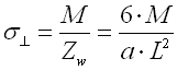
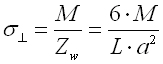
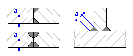
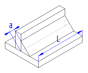
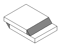
Butt welds originate in the joint gap of connected parts and are usually used as load-bearing, force welds. In order to achieve perfect workmanship of the welds, it is usually necessary to perform modification of the contact surfaces of the connected parts. The method of welded surface treatment is set by the workmanship of the connection, the thickness of the welded parts, the welding method and the accessibility of the welded spot.
When designing and performing the strength checks of welded connections, the weldment with a butt weld is considered as a solid component with a dangerous spot in the area of the weld. The load-bearing weld section will be the basic characteristic of the connection for the assessment of its load-bearing capacity.
In the calculation of butt welds, the type of welds (method of weld surface treatment) or potential weld root reweldment are not considered. The load-bearing section of the butt weld is then specified only by its thickness "a" and length "L".
Note: This program is designed for the calculation of connections with uniform, fully penetrated butt welds. The recommended procedures for handling special cases of connections (partly welded welds, intermittent welds, combined welds) can be found at the end of this chapter.
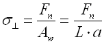
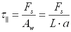
Weld throat thickness:
In order to specify the load-bearing section, the thickness of the thinner of
the welded parts is considered as the butt weld throat thickness "a".
Reinforcement of the weld surface and root is not considered.
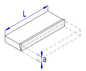
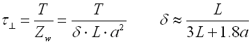
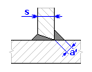
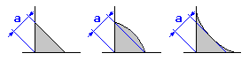
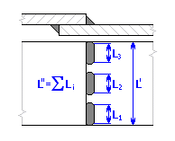
Effective weld length:
In a normal type of weld, so-called "end down-slopes" are formed. They result in
weakening of the section at the weld's beginning and end. The effective weld
length will then be smaller than the actual length (reduced by a worse-quality
weld beginning and end). For more accurate calculations, we therefore recommend
controlling the load-bearing capacity of welds only for that part (length) of
the weld that has a rated section. The common method of setting the effective
length "L" for common weld execution (fig. a) and specially treated welds
(fig. b) is described schematically in the picture.
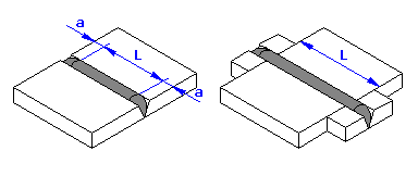
Hint: This program is provided with the function of automatic effective weld length calculation - see the switch on line [2.6].
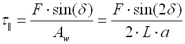
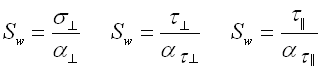
Strength solution of welds:
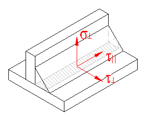
When performing strength checks of butt welds, the rated stress in the
load-bearing weld section must be specified first. Depending on the respective
load, the individual stress components are specified in the direction normal to
the weld (^)
and in the direction parallel to the weld
(ll). The calculated rated stresses must not
exceed the values for the permissible stress.
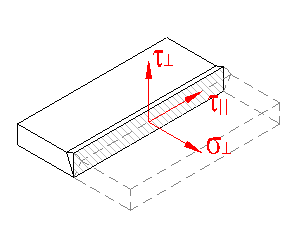
When specifying permissible stresses, the anisotropic properties of the material in the area of the weld must be considered. Different properties of the material result in differing values of permissible stress of the weld in the normal and parallel direction.
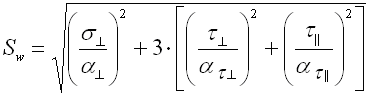
For connections stressed by combined load, the resulting "equivalent" stress
in the weld is specified from the relation:
![]()
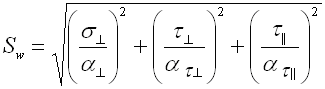
which for sll= 0
can be adjusted as:
![]()
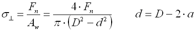
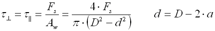
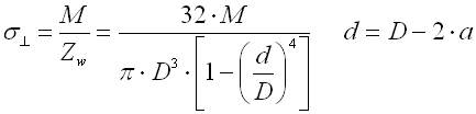
The following table specifies the relations used in the calculation of rated stresses (for respective load and workmanship of the connection):
| Load | Rated stress [MPa, psi] |
| Tensile/Press.
|
 |
| Shear
|
 |
| Bend
|
 |
| Bend
|
 |
| Twist
|
 |
| Tensile
|
|
| Tensile/Press.
|
|
| Shear
|
|
| Bend
|
|
| Tensile/Press.
|
 |
| Shear
|
 |
| Bend
|
 |
| Twist
|
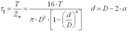 |
where:
a .... weld throat thickness [mm, in]
Aw ... weld throat area [mm2, in2]
D .... tube diameter [mm, in]
d .... weld angle [°]
F .... acting force [N, lb]
Fn ... normal force [N, lb]
Fs ... shear force [N, lb]
L .... effective weld length [mm, in]
M .... bending moment [N mm, lb in]
s^ ...
normal stress vertical to the weld direction [MPa, psi]
sll ...
normal stress parallel to the weld direction [MPa, psi]
T .... torque [N mm, lb in]
t^ ...
shear stress vertical to the weld direction [MPa, psi]
tll ...
shear stress parallel to the weld direction [MPa, psi]
Zw ... module of weld section [mm3, in3]
Connections with partly welded welds:
Connections with partly welded butt welds are usually handled as fillet
welds, with the weld throat (effective) thickness "a".
The other, less appropriate solution method applies to the use of the normal
calculation of butt welds with the weld throat thickness "2a" and adequately
increased safety degree.
Connections with combined welds:
Connections with a combined butt and fillet weld are usually handled as butt
welds with the weld throat (efficient) thickness "a".
Weld throat thickness:
![]()
where for:
![]()
![]()
Connections with intermittent welds:
This program is not primarily modified to handle connections with intermittent
weld. Therefore use the following steps for their calculation:
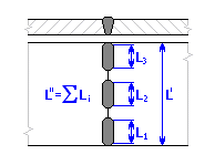
1) Uncheck the switch on line [2.6]
2) For welds loaded only in one direction (subject to tension or shear), check
the connection for the effective weld length L=L''.
3) For connections stressed by bend, twist or combined load, check the
connection for full weld length L=L', while the required weld safety must be
multiplied by the ratio of lengths L'/L''.
Recommendation: We do not recommend the use of intermittent welds for
connections with butt welds.
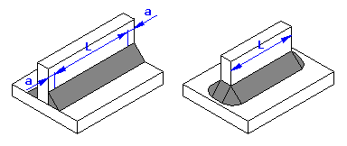
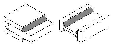
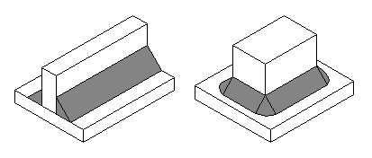
Fillet welds are located along the wedge-shaped edge of connected parts and their basic cross-section includes an isosceles rectangular triangle. They are usually used for load-bearing, force welds in T-shape connections, cross-butt connections, angle connections and for lap joints. The welded parts do not need shape adjustment. For statically loaded connections, usually a flat weld is used, while a concave weld is more appropriate for dynamically loaded connections, as it has lower notch effects.
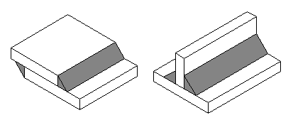
In strength checks of fillet welds, the rectangle lying in the centre plane dividing the weld section into two identical parts is considered the dangerous (load-bearing) weld section. The dimensions of the load-bearing section of a fillet weld are specified by its thickness "a" and length "L".
Note: This program is designed for the calculation of welds with uniform fillet welds. The recommended methods of handling connections with intermittent welds or with combined welds can be found at the end of this chapter.
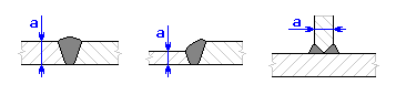
Weld throat thickness:
The fillet weld throat thickness "a" is defined as the height of the
biggest isosceles triangle inscribed into a weld section without penetration.
Recommendation: The fillet weld thickness is chosen depending on the
used material and thickness of the welded parts. As the information regarding
the recommended weld thickness given in the literature differs significantly,
follow the company procedures in choosing the weld thickness. In order to
specify the approximate minimum thickness of the fillet weld, the following
informative relation can be used for the steel strength Rm»370..420
MPa:
![]()
with tmin for thickness of the thinner of the connected materials.
For steels with higher strength (Rm»520
MPa), the weld thickness should be approx. 1 to 2 mm higher.
Effective weld length:
In a normal type of weld, so-called "end down-slopes" are formed. They result in
weakening of the section at the weld's beginning and end. The effective weld
length will then be smaller than the actual length (reduced by a worse-quality
weld beginning and end). For more accurate calculations, we therefore recommend
controlling the load-bearing capacity of welds only for that part (length) of
the weld that has a rated section. A common method of specifying the effective
length "L" depending on the weld workmanship is shown schematically in the
picture.
Hint: This program is provided with a function of automatic effective weld length calculation - see the switch on line [3.12] or [4.12].
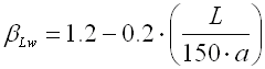
Recommendation: The length of the fillet weld should range between 5a<
L< 70a. For longer welds, it is more practical to use an intermittent weld. For
very long welds (150a<L<400a) stressed in the weld direction, it is necessary,
for the sake of calculation, to perform correction of the effective weld length
using the coefficient:
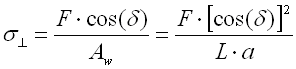
Strength solution of welds:
The rated stress specification in the load-bearing section of the fillet weld is
an extraordinarily complicated task due to the combined load and more jagged
weld. Therefore, a simplified method is used in the calculation for handling
fillet welds that reclines the load-bearing weld section into the plane of
connection of the parts. Depending on the respective load, the individual stress
components are specified in such reclined section, in the direction normal to
the weld (^) and in the direction parallel
to the weld (ll). This convention also includes an assumption that all
components specified like that will actually have a character of the shear
stress. The calculated rated stresses must not exceed the values of permissible
material stress in shear.
When specifying permissible stresses, the anisotropic properties of the material in the area of the weld must be considered. Different properties of the material result in differing values of permissible stress of the weld in the normal and parallel direction.
A common method of handling welds with fillet welds is further presented in a typical example of connecting a beam using a double-sided fillet weld.
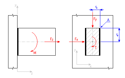
Depending on the acting load, we can use the following relations to specify
the individual components of stress at point "A" of the weld:
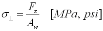
- load with normal force Fz:
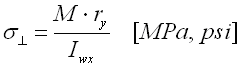
- load with bending moment M:
- load with shear force Fx:
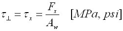
- load with shear force Fy:
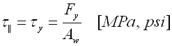
- load with torque T:
where:
Aw ... weld throat area [mm2, in2]
Iw ... moment of inertia of the weld [mm4, in4]
Jw ... polar moment of inertia of the weld [mm4, in4]
s^ ...
normal stress vertical to the weld direction [MPa, psi]
sll ...
normal stress parallel to the weld direction [MPa, psi]
t^ ...
shear stress vertical to the weld direction [MPa, psi]
tll ...
shear stress parallel to the weld direction [MPa, psi]
For connections stressed by combined load, the resulting "equivalent" stress
in the weld is specified from the relation:
![]()
which for sll=
0 can be adjusted as:
![]()
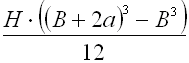
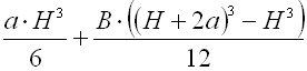
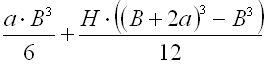
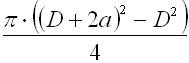
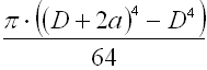
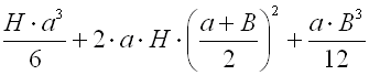
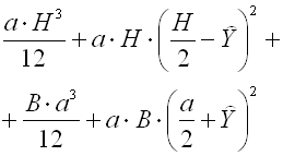
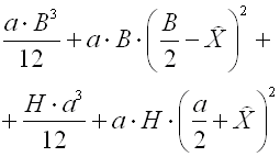
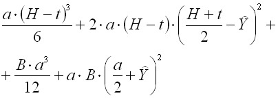
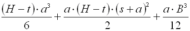
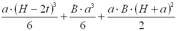
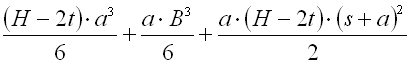
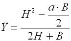
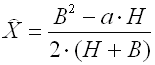
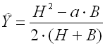
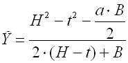
The sectional properties for the selected basic shapes of weld groups can be
found in the following table. In order to specify the polar moment of inertia of
the weld, you can use the following relation:
![]()
| Shape | Aw [mm2, in2] | IwX [mm4, in4] | IwY [mm4, in4] |
|
|
|
 |
 |
|
|
|
 |
 |
|
|
|
 |
 |
|
|
 |
 |
|
|
|
|
 |
 |
|
|
|
 |
 |
|
|
|
 |
 |
|
|
|
 |
 |
| Centre of gravity of weld group: | |||
|
|
 |
||
|
|
 |
 |
|
|
|
 |
||
where:
a .... weld throat thickness [mm, in]
B .... width of weld group [mm, in]
D .... weld diameter [mm, in]
H .... height of weld group [mm, in]
L .... weld length [mm, in]
s .... flange thickness [mm, in]
t .... web thickness [mm, in]
Connections with combined welds:
Connections with a combined butt and fillet weld are usually handled as butt
welds with the weld throat (efficient) thickness "a".
Weld throat thickness:
![]()
where for:
![]()
![]()
Connections with intermittent welds:
This program is not primarily modified to handle connections with intermittent
weld. Therefore use the following steps for their calculation:
1) Uncheck the switch on line [3.12, 4.12]
2) For welds loaded only in one direction (subject to tension or shear), check
the connection for the effective weld length L=L''.
3) For connections stressed by bend, twist or combined load, check the
connection for full weld length L=L', while the required weld safety must be
multiplied by the ratio of lengths L'/L''.
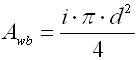
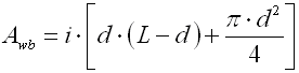
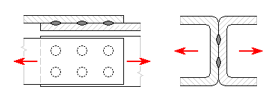
Plug and slot welds are usually used for lap joints. They are not suitable for the transfer of high forces and are especially not suitable for dynamically loaded connections. The connection is formed by the weld on walls of circular or oval openings and in the contact surface of the adjoining part. Plugs and slots of small dimensions are usually fully filled with the weld.
These welds are not suitable for the joining of thicker plates and are usually used for thinner plates up to approx. 15 mm thick. In view of the stress, slot welds are more preferable due to the better quality of penetration of the weld root. A better quality of the weld, i.e. better strength characteristic of the joint, can be achieved by sloped walls of openings.
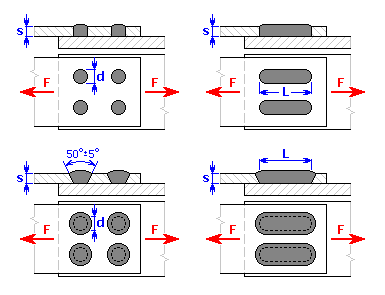
Recommended weld dimensions:
Hole diameter ... d ≥ 2s
Slot width ... d ≥ 2s
Slot length ... L ≥ 2d
Strength solution of welds:
Two types of damage appear in plug and slot welds:
1) shear in the weld base surface
2) tear in the weld circumferential surface
During strength checks, both possible types of damage must be assessed. We
can specify the resulting rated stress from the relation:
![]()
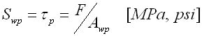
Shear stress in the base surface of the weld:
![]()
Shear stress in the circumferential surface of the weld:
The sizes of calculated weld surfaces Aw are specified for both weld types in the table:
| Plug welds | Slot welds | |
| Base area of weld [mm2, in2] |
 |
 |
| Circumferential area [mm2, in2] |
|
|
where:
F .... acting force [N, lb]
d .... plug weld diameter, or slot weld width [mm, in]
i ..... number of welds
L .... slot weld length [mm, in]
s .... plate thickness [mm, in]
Spot resistance welds are usually used to connect thin plates and thin-walled
parts. They are especially very useful in lot production. The connections with
spot welds are not very appropriate for transferring high forces. In view of the
type of stress, we distinguish two basic types of connections with spot welds:
- connections with welds stressed in shear (lap joints)
- connections with welds stressed in tear (by tension)
In technical practice, not more than 3 parts with maximum total thickness up to approx. 15 mm are allowed to be joined for connections with resistance welds. The thickness ratio for individual parts should not exceed 1:3. The welds should be positioned towards the external force so that they are always only stressed in shear. Spot welds stressed in tension have significantly lower load-bearing capacity, which is why their use is not recommended. Lap welds can be made as single-shear or double-shear. A minimum of 2 and maximum of 5 spot connections should be located in the direction of acting force.
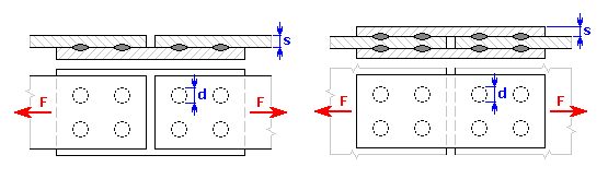
Recommended weld dimensions:
Spot weld diameter ... d »
5 s0.5
Pitch between adjacent welds ... t1 »
(2..3) d
Weld distance from edge of plate ... t2 ≥ 2d
Strength solution of welds:
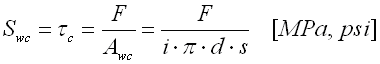
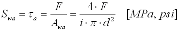
During strength checks, the following checks are carried out for spot welds:
1) Check of weld against tear in cylindrical area
2) Check of weld against shear (for lap joints)
3) Check of weld against separation (for welds stressed in tension)
The calculation is based on the assumption of evenly distributed force F on
all welds. We can specify the resulting rated stress from the relation:
![]()
Shear stress in the cylindrical area of the weld:
Shear stress in the weld throat area:
Normal stress in the weld throat area:
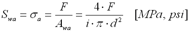
where:
Awa ... area of the spot weld section [mm2, in2]
Awc ... cylindrical area of the weld [mm2, in2]
F .... acting force [N, lb]
d .... spot weld diameter [mm, in]
i ..... number of welds
s .... plate thickness [mm, in]
An accurate theoretical solution to force and strength conditions is an extremely complicated problem for welded connections, even for welds with simple shapes. That is why common technical calculations are based on a range of conventions and simplified premises. That logically results in certain disagreement between the solution models commonly used in practice. That is why the program is provided with an option to select from three different calculation methods.
Although all three specified methods use almost a similar way of theoretical handling of tension in the examined spot of the weld, they differ in the method of evaluating the total load-bearing capacity of the designed connection. That is why each calculation method operates with its own safety rate differing in quality. The choice of an appropriate method will then depend on the user's specific requirements and experience.
The following paragraphs provide a detailed description of individual calculation methods.
This method represents a general method of handling welded connections and is based on the most frequent calculation methods for welded connections of machinery equipment mentioned in the literature.
Depending on the respective type, workmanship and load of the welded
connection, this method calculates the respective theoretical rated stress in
the load-bearing weld section (normal, shear, or equivalent) in the first step.
The strength checks of the weld are then performed by simple comparison of the
calculated stress to the yield strength of the basic material. With respect to
the type of calculated stress, we can describe the conditions of the
load-bearing capacity of the weld using the following relations

The required safety of the weld stress is then the ratio between the value of
the yield strength of the basic material and the value of the maximum admissible
stress of the specific weld.
This method is disadvantageous due to the rather complicated procedure in specifying the suitable safety rate minimum value. In addition to the common (qualitative) criteria, specific factors of the specific welded connection (type, workmanship and the way of connection load) must be considered when choosing the required safety. The required safety for the yield strength "FSy" is then defined as the product of two safety coefficients FSy = FS1 * FS2.
Safety coefficient FS1:
Depends on the direction of the acting stress and the anisotropic properties of
the material in the examined weld spot. Its value should also consider the
technological weld parameters. With respect to the type, workmanship and the way
of connection load, it is chosen from the range 1 to 2.
Safety coefficient FS2:
It considers qualitative parameters. With respect to the accuracy and value of
input information, connection importance, production quality, operating
conditions and calculation accuracy, it is usually chosen from 1.1 to 2.
This method expands the basic calculation method and brings certain simplification to the area of considering the designed joint load-bearing capacity. As in the previous method, the respective theoretical rated stresses in the load-bearing weld section are calculated first. In the next step, the resulting comparative stress is defined based on these rated stresses using the predefined empirically set conversion coefficients. These coefficients consider the anisotropic properties of weld material in the direction of the acting stresses and their size will therefore depend on the type, workmanship and the way of load of the welded joint.
Depending on the acting stress, the resulting comparative stress will be
specified for the respective conversion coefficients "a"
from the following relations:
- in linear state of stress
- in multi-axial stress of butt welds
- in multi-axial stress of fillet welds
The strength checks of the weld are then performed by comparison of the
calculated comparative stress to the yield strength of the basic material.
Regardless of the type, workmanship or the way of load of the welded joint, we
can describe the condition of load-bearing capacity using a single relation:
The required safety against the yields point "FSy" will
consider only the qualitative parameters of the welded connection for this
method. With respect to the accuracy and value of input information, connection
importance, production quality, operating conditions and calculation accuracy,
it is usually chosen from 1.1 to 2.
The most complicated task in the strength checks of welded connections usually applies to defining the correct value of the permissible weld stress. The logical result is therefore the fact that it is this area of specifying the permissible stresses where the most noticeable differences between various recommended procedures used in technical practice appear.
The previous calculation methods control the load-bearing capacity of the joint by simple comparison of calculated stresses to the yield strength of the basic material. They do not provide for direct handling of the requirement of strength checks for the known values of permissible weld stress prescribed by the standards or company procedures. This method therefore obliges users who want to use this program to design the joint and at the same time comply with the prescribed procedures for the strength checks.
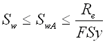
Unlike the previous method, this method uses the comparison of calculated
stresses to the value of permissible stress "SwA"
defined directly by the user for strength checks. The condition of load bearing
capacity of the welded connection may then be described using the relation:

As the required safety level is usually already included in the value of the
prescribed permissible stress, the applied safety degree "FS"
is used as an auxiliary quantity and only describes a certain degree of
"over-dimensioning" of the designed connection. The safety value "FS" will then
depend on the procedure applied by the user in order to define the permissible
stress, and it is usually FS≥1.
A typical calculation / connection design includes the following steps:
Use this paragraph to set the control parameters for the calculation (calculation method and calculation units) and choose the appropriate material for the connected parts.
In the selection list, choose the desired calculation unit system. All values will be recalculated immediately after switching to other units.
An accurate theoretical solution to force and strength conditions is an extremely complicated problem for welded connections, even for welds with simple shapes. That is why common technical calculations are based on a range of conventions and simplified premises. That logically results in certain disagreement between the solution models commonly used in practice. That is why the program is provided with an option to select from three different calculation methods.
Although all three specified methods use almost a similar way of theoretical handling of tension in the examined spot of the weld, they differ in the method of evaluating the total load-bearing capacity of the designed connection. That is why each calculation method operates with its own safety rate differing in quality. The choice of an appropriate method will then depend on the user's specific requirements and experience.
Select the appropriate calculation method using the appropriate switch. Define the required connection safety for the selected method.
This method represents a general method of handling welded connections and is based on the most frequent calculation methods for welded connections of machinery equipment mentioned in the literature.
Depending on the respective type, workmanship and load of the welded connection, this method calculates the respective theoretical rated stress in the load-bearing weld section (normal, shear, or equivalent) in the first step. The strength checks of the weld are then performed by simple comparison of the calculated stress to the yield strength of the basic material. The required safety of the weld stress is then the ratio between the value of the yield strength of the basic material and the value of the maximum admissible stress of the specific weld.
This method is disadvantageous due to the rather complicated procedure in specifying the suitable safety rate minimum value. In addition to the common (qualitative) criteria, specific factors of the specific welded connection (type, workmanship and the way of connection load) must be considered when choosing the required safety. The required safety for the yield strength "FSy" is then defined as the product of two safety coefficients FSy = FS1 * FS2.
Safety coefficient FS1:
Depends on the direction of the acting stress and the anisotropic properties
of the material in the examined weld spot. Its value should also consider the
technological weld parameters.
| Butt welds | |
| - subject to compression | 1 |
| - subject to tension / bending | 1 ... 1.2 |
| - subject to shear | 1.4 ... 1.5 |
| * higher values - one-sided
welded welds, unworked welds, manual arc or flame welding * lower values - double-sided welded welds, worked welds and welds with rewelded root, automatic welding in CO2 or under welding flux, electroslag welding |
|
| Fillet welds | |
| - end welds | 1.2 ... 1.5 |
| - side welds | 1.3 ... 1.6 |
| * higher values - flat welds,
unfinished welds, welds without penetration, thicker welds, manual welding
* lower values - concave welds, penetrated welds, lower-thickness welds, automatic welding in CO2 or under welding flux |
|
| Plug and slot welds | |
| - subject to shear | 1.5 ... 2 |
| * higher values - welds with
vertical walls, manual arc welding * lower values - welds with sloped walls, welding in CO2 or under welding flux |
|
| Spot resistance welds | |
| - subject to shear | 1.5 |
| - subject to tear | 2 |
Safety coefficient FS2:
It considers qualitative parameters. With respect to the accuracy and
value of input information, connection importance, production quality, operating
conditions and calculation accuracy, it is usually chosen from 1.1 to 2.
| 1.1 ... 1.3 | - very accurate input information - perfect knowledge of material characteristics - high quality and exact observance of production technology - high-quality welds without internal tensions - welding is performed only by very experienced, certified welders - weld quality guaranteed by a detailed output control (radioscopy, magnetic tests, ultrasonic, ..) - insignificant connections without serious impacts in case of damage |
| 1.3 ... 1.6 | - less accurate calculation without experimental
verification - lower accuracy in production technology - standard-quality welds - welding performed by qualified welders - welds with a standard output control - less important connections |
| 1.6 ... 2.0 | - reduced accuracy of calculations - approximate specification of material characteristics - inaccurate knowledge of actual action of external load - welds with increased risk of existence of internal tensions - welds with unguaranteed quality - very important connections with danger to life or high material losses in case of damage |
Note: For connections operating in a corrosive environment or at high temperatures, higher values for safety coefficient FS2 are also used.
This method expands the basic calculation method and brings certain simplification to the area of considering the designed joint load-bearing capacity. As in the previous method, the respective theoretical rated stresses in the load-bearing weld section are calculated first. In the next step, the resulting comparative stress is defined based on these rated stresses using the predefined empirically set conversion coefficients. These coefficients consider the anisotropic properties of weld material in the direction of the acting stresses and their size will therefore depend on the type, workmanship and the way of load of the welded joint.
The strength checks of the weld are then performed by comparison of the calculated comparative stress to the yield strength of the basic material. The required safety against the yields point "FSy" will consider only the qualitative parameters of the welded connection for this method. With respect to the accuracy and value of input information, connection importance, production quality, operating conditions and calculation accuracy, it is usually chosen from 1.1 to 2.
| 1.1 ... 1.3 | - very accurate input information - perfect knowledge of material characteristics - high quality and exact observance of production technology - high-quality welds without internal tensions - welding is performed only by very experienced, certified welders - weld quality guaranteed by a detailed output control (radioscopy, magnetic tests, ultrasonic, ..) - insignificant connections without serious impacts in case of damage |
| 1.3 ... 1.6 | - less accurate calculation without experimental
verification - lower accuracy in production technology - standard-quality welds - welding performed by qualified welders - welds with a standard output control - less important connections |
| 1.6 ... 2.0 | - reduced accuracy of calculations - approximate specification of material characteristics - inaccurate knowledge of actual action of external load - welds with increased risk of existence of internal tensions - welds with unguaranteed quality - very important connections with danger to life or high material losses in case of damage |
Note: For connections operating in a corrosive environment or at high temperatures, higher values for safety coefficient FSy are also used.
The most complicated task in the strength checks of welded connections usually applies to defining the correct value of the permissible weld stress. The logical result is therefore the fact that it is this area of specifying the permissible stresses where the most noticeable differences between various recommended procedures used in technical practice appear.
The previous calculation methods control the load-bearing capacity of the joint by simple comparison of calculated stresses to the yield strength of the basic material. They do not provide for direct handling of the requirement of strength checks for the known values of permissible weld stress prescribed by the standards or company procedures. This method therefore obliges users who want to use this program to design the joint and at the same time comply with the prescribed procedures for the strength checks.
Unlike the previous method, this method uses the comparison of calculated stresses to the value of permissible stress "SwA" defined directly by the user for strength checks. As the required safety level is usually already included in the value of the prescribed permissible stress, the applied safety degree "FS" is used as an auxiliary quantity and only describes a certain degree of "over-dimensioning" of the designed connection. The safety value "FS" will then depend on the procedure applied by the user in order to define the permissible stress, and it is usually FS≥1.
This paragraph is used for the selection of suitable material for the connected parts.
The list on line [1.10] is used for selection of the required material standard. Choose the material for the connected parts proper from the list [1.11]. The first five rows of the list is reserved for materials defined by the user. Information and settings of proper materials can be found in the document "Workbook (calculation) modifications". Other rows of the list include a selection of materials for the actually specified standard [1.10].
Select the required national standard from the list to determine the joint material.
This paragraph is intended for the geometrical design and strength checks of connections with butt welds.
Butt welds originate in the joint gap of connected parts and are usually used as load-bearing, force welds. In order to achieve perfect workmanship of the welds, it is usually necessary to perform modification of the contact surfaces of the connected parts. The method of welded surface treatment is set by the workmanship of the connection, the thickness of the welded parts, the welding method and the accessibility of the welded spot.
Designing procedure for the connection:
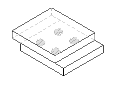
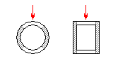
Check the switch with the respective image to select the required connection type.
Use this paragraph to set all required connection dimensions.
In a normal type of weld, so-called "end down-slopes" are formed. They result in weakening of the section at the weld's beginning and end. The effective weld length will then be smaller than the actual length (reduced by a worse-quality weld beginning and end). For more accurate calculations, we therefore recommend controlling the load-bearing capacity of welds only for that part (length) of the weld that has a rated section.
Check this switch in order to consider only the effective weld length during the strength checks of the connection. The program will set the effective length automatically from the specified dimensions. If the check box is unchecked, the load-bearing capacity of the weld will be calculated directly for the dimensions of the connection set in paragraph [2.2].
Check the appropriate check boxes to the left of this paragraph to set the respective weld load combination. Specify the size for the selected loads.
If "Basic calculation method" or "Method of conversion coefficients" (see [1.3] or [1.5]) is used, the strength checks of the connection are performed by comparison of the calculated theoretical stress in the weld [2.16] to the yield strength of the selected material of the connection [2.14]. If the connection is to conform, the resulting safety against yield point [2.17] must be higher than the safety required ([1.4] or [1.6]).
If "Method of permissible stresses" (see [1.7]) is used for calculation, the strength checks of the connection will be performed by comparison of the calculated theoretical stress [2.16] to the permissible stress [2.15]. If the connection is to conform, the resulting safety rate [2.17] must be higher than the safety required [1.8].
If "Method of permissible stresses" (see. [1.7]) is used for the calculation, set the value for the permissible stress of the connection material on this line. This value is then used for defining the safety rate [2.17] of the designed connection.
Fillet welds are located along the wedge-shaped edge of connected parts and their basic cross-section includes an isosceles rectangular triangle. They are usually used for load-bearing, force welds in T-shape connections, cross-butt connections, angle connections and for lap joints. The welded parts do not need shape adjustment. For statically loaded connections, usually a flat weld is used, while a concave weld is more appropriate for dynamically loaded connections, as it has lower notch effects.
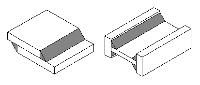
This part of the calculation is used for the geometrical design and strength checks of fillet weld connections loaded in the connection plane. Typical examples of such connections include lap joints and double-sided connections of short rigid beams.
Designing procedure for the connection:
Use a switch with the respective picture to choose the required type of connection (form of weld group).
Use this paragraph to set all required connection dimensions.
The fillet weld throat thickness is defined as the height of the biggest isosceles triangle inscribed into a weld section without penetration.
This paragraph is used to enable the setting (automatic completion) of the respective dimensions of the connection [3.2] for connections with welded on beams with standardized profiles.
When choosing the profile, proceed as follows:
In a normal type of weld, so-called "end down-slopes" are formed. They result in weakening of the section at the weld's beginning and end. The effective weld length will then be smaller than the actual length (reduced by a worse-quality weld beginning and end). For more accurate calculations, we therefore recommend controlling the load-bearing capacity of welds only for that part (length) of the weld that has a rated section.
Check this switch in order to consider only the effective weld length during the strength checks of the connection. The program will set the effective length automatically from the specified dimensions. If the check box is unchecked, the load-bearing capacity of the weld will be calculated directly for the dimensions of the connection set in paragraph [3.2].
Only check this check box if the connection is formed by the fillet weld made on the inside circumference of one of the parts connected.
Choose the required joint design from the drop-down menu.
Check the appropriate check boxes to the left of this paragraph to set the respective weld load combination. Specify the size for the selected loads.
If "Basic calculation method" or "Method of conversion coefficients" (see [1.3] or [1.5]) is used, the strength checks of the connection are performed by comparison of the maximum calculated theoretical stresses [3.27 - 3.30] to the yield strength of the selected material of the connection [3.25]. If the connection is to conform, the resulting safety against yield point [3.31] must be higher than the safety required ([1.4] or [1.6]).
If "Method of permissible stresses" (see [1.7]) is used for calculation, the strength checks of the connection will be performed by comparison of the maximum calculated theoretical stresses [3.27 - 3.30] to the permissible stress [3.26]. If the connection is to conform, the resulting safety rate [3.31] must be higher than the safety required [1.8].
If "Method of permissible stresses" (see. [1.7]) is used for the calculation, set the value for the permissible stress of the connection material on this line. This value is then used for defining the safety rate [3.31] of the designed connection.
Fillet welds are located along the wedge-shaped edge of connected parts and their basic cross-section includes an isosceles rectangular triangle. They are usually used for load-bearing, force welds in T-shape connections, cross-butt connections, angle connections and for lap joints. The welded parts do not need shape adjustment. For statically loaded connections, usually a flat weld is used, while a concave weld is more appropriate for dynamically loaded connections, as it has lower notch effects.
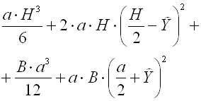
This part of the calculation is used for the geometrical design and strength checks of fillet weld connections loaded in the plane perpendicular to the connection plane. A typical example of such connections is the connection of beams to the base plate (T-connection).
Designing procedure for the connection:
Use a switch with the respective picture to choose the required type of connection (form of weld group).
Use this paragraph to set all required connection dimensions.
The fillet weld throat thickness is defined as the height of the biggest isosceles triangle inscribed into a weld section without penetration.
This paragraph is used to enable the setting (automatic completion) of the respective dimensions of the connection [4.2] for connections with welded on beams with standardized profiles.
When choosing the profile, proceed as follows:
In a normal type of weld, so-called "end down-slopes" are formed. They result in weakening of the section at the weld's beginning and end. The effective weld length will then be smaller than the actual length (reduced by a worse-quality weld beginning and end). For more accurate calculations, we therefore recommend controlling the load-bearing capacity of welds only for that part (length) of the weld that has a rated section.
Check this switch in order to consider only the effective weld length during the strength checks of the connection. The program will set the effective length automatically from the specified dimensions. If the check box is unchecked, the load-bearing capacity of the weld will be calculated directly for the dimensions of the connection set in paragraph [4.2].
In welded-on beams loaded by bending moment, the normal stress with the shape described in the picture is formed in the weld. The maximum stress then acts in the extreme points of the weld group that are most distant from the neutral axis.
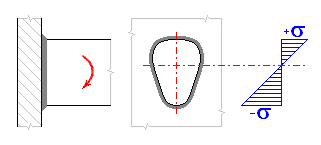
As is obvious from the picture, the stress in the upper weld acts in the direction of the tear of the beam and has the character of tensile stress. The stress in the lower weld will then have the character of compression stress. In the welds symmetrical along the neutral axis, the value of both stresses will be the same; in the asymmetrical welds, the values of compression stress may be higher. In view of the load-bearing capacity of the welded connection, however, the tensile stress is usually more important for beams connected in that way.
In normal calculation, the program assesses the maximum calculated stress regardless of its direction during the strength checks. By checking this switch, you will suppress the check of compression (negative) stresses. During the strength checks, the program will assess only the tensile (positive) stress.
Check the appropriate check boxes to the left of this paragraph to set the respective weld load combination. Specify the size for the selected loads.
If "Basic calculation method" or "Method of conversion coefficients" (see [1.3] or [1.5]) is used, the strength checks of the connection are performed by comparison of the maximum calculated theoretical stresses [4.27, 4.28] to the yield strength of the selected material of the connection [4.25]. If the connection is to conform, the resulting safety against yield point [4.29] must be higher than the safety required ([1.4] or [1.6]).
If "Method of permissible stresses" (see [1.7]) is used for calculation, the strength checks of the connection will be performed by comparison of the maximum calculated theoretical stresses [4.27, 4.28] to the permissible stress [4.26]. If the connection is to conform, the resulting safety rate [4.29] must be higher than the safety required [1.8].
If "Method of permissible stresses" (see. [1.7]) is used for the calculation, set the value for the permissible stress of the connection material on this line. This value is then used for defining the safety rate [4.29] of the designed connection.
This paragraph is intended for the geometrical design and strength checks of connections with plug and slot welds.
Plug and slot welds are usually used for lap joints. They are not suitable for the transfer of high forces and are especially not suitable for dynamically loaded connections. The connection is formed by the weld on walls of circular or oval openings and in the contact surface of the adjoining part. Plugs and slots of small dimensions are usually fully filled with the weld.
These welds are not suitable for the joining of thicker plates and are usually used for thinner plates up to approx. 15 mm thick. In view of the stress, slot welds are more preferable due to the better quality of penetration of the weld root. A better quality of the weld, i.e. better strength characteristic of the joint, can be achieved by sloped walls of openings.
Designing procedure for the connection:
Choose the required type of connection from the drop-down menu.
Use this paragraph to set all required connection dimensions.
Set the appropriate value for the connection loading on line [5.8].
If "Basic calculation method" or "Method of conversion coefficients" (see [1.3] or [1.5]) is used, the strength checks of the connection are performed by comparison of the maximum calculated theoretical stresses [5.12, 5.13] to the yield strength of the selected material of the connection [5.10]. If the connection is to conform, the resulting safety against yield point [5.14] must be higher than the safety required ([1.4] or [1.6]).
If "Method of permissible stresses" (see [1.7]) is used for calculation, the strength checks of the connection will be performed by comparison of the maximum calculated theoretical stresses [5.12, 5.13] to the permissible stress [5.11]. If the connection is to conform, the resulting safety rate [5.14] must be higher than the safety required [1.8].
If "Method of permissible stresses" (see. [1.7]) is used for the calculation, set the value for the permissible stress of the connection material on this line. This value is then used for defining the safety rate [5.14] of the designed connection.
This paragraph is intended for the geometrical design and strength checks of connections with spot welds.
Spot resistance welds are usually used to connect thin plates and thin-walled
parts. They are especially very useful in lot production. The connections with
spot welds are not very appropriate for transferring high forces. In view of the
type of stress, we distinguish two basic types of connections with spot welds:
- connections with welds stressed in shear (lap joints)
- connections with welds stressed in tear (by tension)
In technical practice, not more than 3 parts with maximum total thickness up to approx. 15 mm are allowed to be joined for connections with resistance welds. The thickness ratio for individual parts should not exceed 1:3. The welds should be positioned towards the external force so that they are always only stressed in shear. Spot welds stressed in tension have significantly lower load-bearing capacity, which is why their use is not recommended. Lap welds can be made as single-shear or double-shear. A minimum of 2 and maximum of 5 spot connections should be located in the direction of acting force.
Designing procedure for the connection:
Check the switch with the respective image to select the required connection type.
Use this paragraph to set all required connection dimensions.
Set the appropriate value for the connection loading on line [6.7].
If "Basic calculation method" or "Method of conversion coefficients" (see [1.3] or [1.5]) is used, the strength checks of the connection are performed by comparison of the maximum calculated theoretical stresses [6.11, 6.12] to the yield strength of the selected material of the connection [6.9]. If the connection is to conform, the resulting safety against yield point [6.13] must be higher than the safety required ([1.4] or [1.6]).
If "Method of permissible stresses" (see [1.7]) is used for calculation, the strength checks of the connection will be performed by comparison of the maximum calculated theoretical stresses [6.11, 6.12] to the permissible stress [6.10]. If the connection is to conform, the resulting safety rate [6.13] must be higher than the safety required [1.8].
If "Method of permissible stresses" (see. [1.7]) is used for the calculation, set the value for the permissible stress of the connection material on this line. This value is then used for defining the safety rate [6.13] of the designed connection.
Information on setting of calculation parameters and setting of the language can be found in the document "Setting calculations, change the language".
Depending on the applied calculation method (see the main calculation [1.2]) you can use this part to set some parameters affecting the calculation of the welded connections proper. In paragraph [3.1] you can set the required value of the coefficients used for "Method of conversion coefficients". Paragraph [3.10] is used to set the basic calculation parameters for "Method of permissible stresses".
Use this paragraph to set the values of conversion coefficients used by the program in the calculation of comparative stresses for "Method of conversion coefficients".
| Weld type, way of load | Coefficient |
| Butt welds subject to compression | 1.00 |
| Butt welds subject to tension - manual arc or flame welding - contact resistance welding - manual welding, connections after slotting with rewelded root - automatic welding under welding flux or in CO2 , double-sided welded connections - electroslag welding |
0.85 ... 1.00 » 0.85 » 0.90 » 0.95 » 1.00 » 1.00 |
| Butt welds subject to shear | 0.70 |
| End fillet welds - manual welding, weld without penetration - manual arc welding, electrodes with higher strength (min. 20% more) - automatic welding under welding flux or in CO2 , weld thickness > 8mm, penetration depth 0.2a - automatic welding under welding flux, single-layer welds less than 8mm thick, penetration depth 0.4a |
0.75 ... 1.00 » 0.75 » 0.85 » 0.90 » 1.00 |
| Side fillet welds - manual welding, weld without penetration - manual arc welding, electrodes with higher strength (min. 20% more) - automatic welding under welding flux or in CO2 , weld thickness > 8mm, penetration depth 0.2a - automatic welding under welding flux, single-layer welds less than 8mm thick, penetration depth 0.4a |
0.65 ... 0.90 » 0.65 » 0.75 » 0.80 » 0.90 |
| Plug and slot welds - manual arc welding, welds with vertical walls - welding under welding flux or in CO2 , welds with sloped walls |
0.50 ... 0.65 » 0.50 » 0.65 |
| Spot resistance welds subject to shear | 0.65 |
| Spot resistance welds subject to tension | 0.50 |
Use the appropriate switch to select the required relation that will be further used in the calculation of comparative stress.
For butt-welded connections, technical calculations most frequently use the
second relation,
![]()
which is also applied by the program in "Basic calculation method". If this
relation is used, the permissible tensile stress of the basic material is
usually used to define the permissible stress in the weld section.
The first relation
![]()
is used to define the rated stresses in a butt weld section less frequently.
This method is used e.g. in DIN 18800, or for a simplified calculation method
according to prEN 1993-1-8. Generally, we can say that if used, the value of the
permissible stress should be derived based on the permissible stress of the
material in shear.
Use the appropriate switch to select the required relation that will be further used in the calculation of comparative stress.
For fillet-welded connections, the technical calculations almost solely use
the first relation,
![]()
which is also applied by the program in "Basic calculation method". When this
relation is used, the permissible stress in shear of the basic material is
usually used to define the permissible stress in the weld section.
With respect to the established calculation convention (for the sake of the
calculation, the load-bearing weld section is reclined into the plane of
connecting the parts), the literature mentions the second relation for fillet
welds only very rarely.
![]()
If you still use it, the value of the permissible stress should be derived based
on the permissible tension stress of the material.
In some technical calculations, the theory of shear stress distribution is used for strength checks of fillet welds subject to shear force in the plane of connection of parts. According to this theory, the shear stresses in the loaded section are transferred only by the welds parallel to the stress direction. When checking this switch, the program will use the reduced load-bearing section of the weld group in calculation of shear stresses.
General information on how to modify and extend calculation workbooks is mentioned in the document "Workbook (calculation) modifications".
^