The calculation is designed to create a detail drawing of involute spline.
Information on the syntax and control of the calculation can be found in the document "Control, structure and syntax of calculations".
1. Select the calculation units. [1.1].
2. Select the profile angle. [1.2].
3. Enter the module or Diametral Pitch [1.3, 1.4].
4. Enter the number of grooving teeth [1.5].
5. On the line [1.7], check the radio button and enter the grooving diameters
[1.7, 1.8] and the shift xm [1.10]. You can make use of the shaft coupling
calculation, in which these values are mentioned for various standards.
6. Select the tool head diameter on the line [2.3] based on the requirement of
flat or rounded grooving. Eventually tune the tooth shape according to your
requirements (see the paragraph [2.0] for more details).
7. Generate the grooving profile in the paragraph [6.0].
In this section, input (copy) parameters of splines from the main calculation of involute splines. If the checkbox [1.8] is checked, diameters are filled with values according to ISO4156. After unchecking, you can enter custom values.
Use the drop-down menu to choose the required system of units for calculation. After the units are switched, all values will immediately be re-calculated automatically. At the same time, the grooving parameters will be prefilled according to ANSI B92.1 (30°, flat root, side fit) for imperial units and ISO 4156 (30° flat root, side fit) for metric units.
Select the basic profile angle from the list (or enter your value).
In the right drop-down menu, there are standardized module values / Diametral Pitch and the value selected from this menu is added automatically to the box on the left. Use the selection on the right to switch between the option to set the module or Diametral Pitch.
Enter the number of teeth.
Check the button and enter the diameter values.
In some standards, a basic profile shift is defined for grooving. This influences mainly the tooth thickness. The shift value may be changed using the slider on [1.9]. Another possibility is to enter the value directly on [1.10]. Enter the shift value in the actually selected units (mm/inch). After checking the button on [1.10], it is possible to set a different profile shift for the hub (you can obtain some backlash here).
In some cases, it may be useful to enter the tooth thickness and calculate the corresponding profile shift. In that case, enter the required thickness and press the ">x1" button. The shift value will be calculated [1.10].
In certain cases, a tooth backlash has to be specified. If this is the case, enter the value (the current value is on the right side) and press ">x1" or ">x2" button to change the profile shift so that the required backlash is obtained.
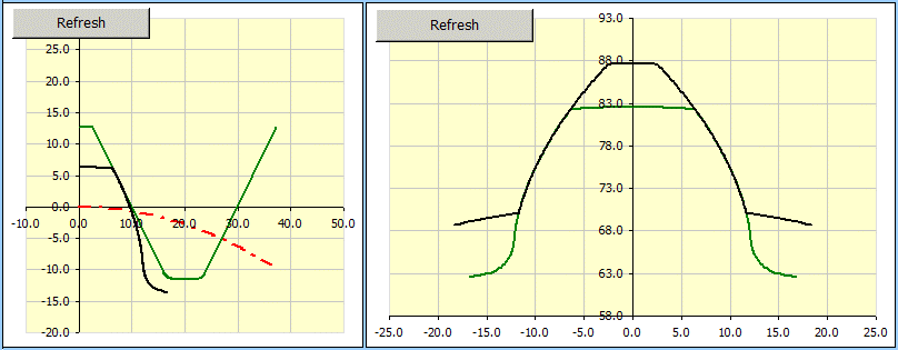
On the left there is a detail of a machine tool (the machining process may be simulated). The accurate shape of the tooth is black and the accurate shape of the machine tool is green. The right picture shows the shape of the tooth shaft (green) and the shape of the tooth hub (black).
Use this line to specify which detailed tooth and tool profile is to be displayed. Use the slider on the right to set the tool turn in cut.
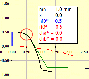
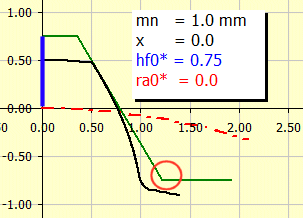
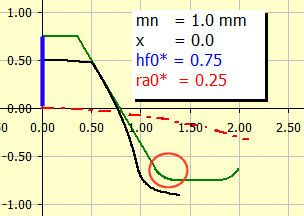
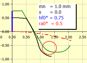
The tooth shape in the root and head area may be tuned by setting the tool profile parameters. The tool shape is specified by the parameters according to the pictures. The values should be entered in the module multiples (left cells). The automatically calculated values in mm/inch are displayed on the right side.
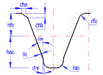
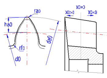
The meaning and influence of individual parameters is best shown in the pictures. The right half of the tooth is shown in the black colour whereas the left half of the tool is shown in green (gear rack). The principle of generating the gearing shape is described in the chapter [6].
The change of hf0*
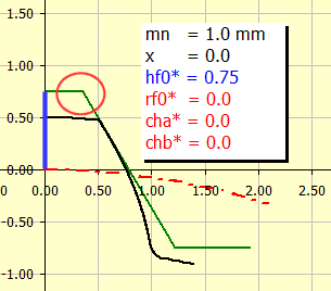
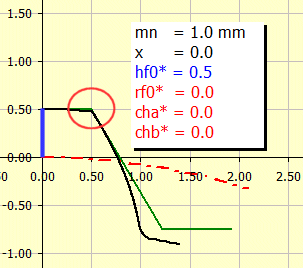
The change of cha*, chb* and hf0* (tooth head chamfer).
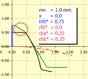
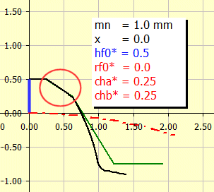
The change of rf0* and hf0* (tooth head radius).
The change of ra0* (tooth root radius).
It results from the required values of "Dre / Dri" and cannot be changed.
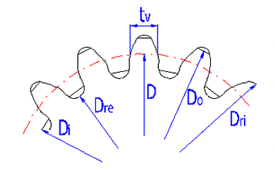
This paragraph includes a well-arranged listing of all basic dimensional parameters of splines. An informational illustration of the most important dimensional parameters is given here.

This paragraph contains the spline check dimensions and the correction settings to obtain them.
This paragraph specifies two basic check dimensions
of toothing. They are the dimension across the teeth W [4.4] and dimension
across the rolls and balls M [4.7]. After checking the check box to the right
of the value of number of teeth that the measurement applies to [4.3] and the
diameter of roll/ball [4.6] you can set your own values. Other check dimensions
required for production of toothing are tied to fitting of toothed wheels and
manufacturing method and therefore close cooperation of a designer and a
technologist is appropriate.
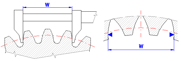
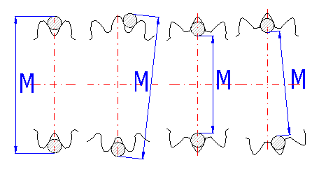
If you try to find the parameters of an unknown wheel, it is possible to use this tool. Measure the relevant check dimension on the wheel, enter it in the respective input field and the calculation will modify the correction x1 (x2) so that the calculated W or M dimension agrees with the measured value.
In practice, you face quite frequently a situation where the splines is unknown and it is necessary to calculate its parameters (competition comparison, production of a spare gear, etc.). Therefore, this provides a simple tool to facilitate the primary calculation of the basic parameter - module.
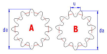
It is obvious that the mentioned procedure needs certain skills and experience, nevertheless, in case of common gearing, where production using common standardized tools and procedures can be assumed, this procedure leads to quite reasonable results.
Information on options of 2D and 3D graphic outputs and information on cooperation with 2D and 3D CAD systems can be found in the document "Graphic output, CAD systems".
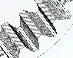
Tooth flank is calculated from the simulation of the tool bite with the machined wheel which enables determining the exact tooth shape including the tooth flank. A detailed drawing of the whole toothing can be used as a document for manufacturing an accurate model in 3D CAD system, or as input data for manufacturing the splines.
The table on sheet "Coordinates" gives the coordinates of points on the right side of the tooth line in the system of X,Y coordinates with point 0,0 in the wheel centre. In order to recalculate and generate the current coordinates according to the settings from paragraph [6] press button "Refresh".
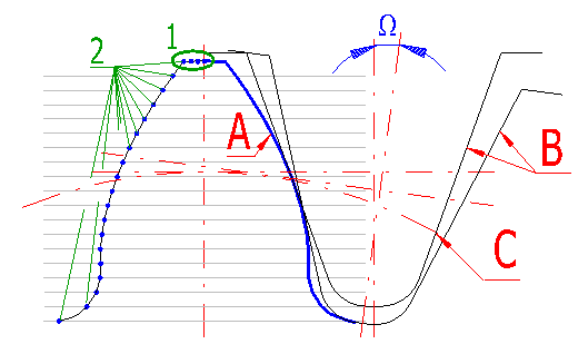
Production tool (B) with dimensions defined in paragraph [2] is gradually rolled away along the circle (C) with step of angle W and thus creates the tooth line (A) in individual points (2).
Specify the number of teeth which shall be drawn in partial drafting.
Define the number of points (sections) on the tooth tip, see picture [19.4],
reference (1).
Range of permitted values: <2 - 50>, recommended: 5
Define the number of points (sections) which form a complete tooth flank, see
picture [19.4], reference (2).
Range of permitted values: <10 - 500>, recommended: 30 and more
It defines the increment of angle for rolling (turning) of the tool during
machining of the tooth flank see picture [19.4], angle W.
Extent of permitted values: <0.02 - 10>, recommended: 0.5
You can set the angle to affect the first tooth angle (the tooth gap for the internal gearing) towards the respective gear centre. For the zero gear angle, the first tooth is drawn upwards on the vertical axis. The positive angle turns the respective gear in the counter-clockwise direction. In order to simplify the setting of the position (gear angle) of individual gearwheels or their parts, the four buttons on this line are used.
Switch "Drawing without axes" defines if the axes will be removed in the inserted drawing.
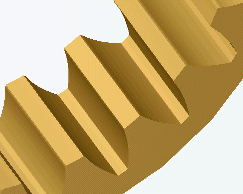
Example of 3D model
Information on setting of calculation parameters and setting of the language can be found in the document "Setting calculations, change the language".
General information on how to modify and extend calculation workbooks is mentioned in the document "Workbook (calculation) modifications".
^