The calculation is intended for the geometric design and strength check of couplings using pins and clevis pins. The program is used to solve the following tasks:
The calculation is based on data, procedures and algorithms from specialized literature and standards ANSI, ISO, DIN and others.
List of standards: ANSI B18.8.1, ANSI B18.8.2, ISO 2338, ISO 2339, ISO 2340, ISO 2341, ISO 8733, ISO 8734, ISO 8735, ISO 8739, ISO 8740, ISO 8741, ISO 8742, ISO 8743, ISO 8744, ISO 8745, ISO 8746, DIN 1, DIN 7, DIN 1443, DIN 1444, DIN 1470, DIN 1471, DIN 1472, DIN 1473, DIN 1474, DIN 1475, DIN 1476, JIS B 1352, JIS B 1354, JIS B 1355, BS EN 22339, BS EN 22340, BS EN 22341, CSN EN 22339, CSN EN 22340, CSN EN 22341
User interface.
Download.
Purchase, Price list.
Information on the syntax and control of the calculation can be found in the document "Control, structure and syntax of calculations".
Information on the purpose, use and control of the paragraph "Information on the project" can be found in the document "Information on the project".
Connecting pins serve to make strong, detachable connections between two mechanical parts, to secure their positions accurately, and to eliminate transversal shifting forces. As a rule, standardized pins manufactured in a wide range of dimensions and designs are used. Pre-stress in the connection between parts is achieved either by means of pin allowance against the hole or the use of conical pins. Conical pins are self-locking and have taper ratio 1: 50. Cylindrical pins are produced as either plain or grooved.

Clevis pins are used for detachable, rotating connections of mechanical parts. As a rule, these connections transfer only transversal forces acting perpendicularly on the clevis pin axis. Clevis pins are generally fitted with a clearance to form coupled connections (rod-clevis couplings). Clevis pins can also be used for short axles of pulleys, travel wheels, etc. The H11/h11, H10/h8, H8/f8, H8/h8, D11/h11, D9/h8 fitting methods are most frequently used. Connecting clevis pins should be secured against axial movement by means of cotter pins, flexible safety rings, nuts, adjusting rings, etc. Standardized clevis pins are produced in versions with or without heads, in which case they are provided with holes for cotter pins.

Pinned couplings are sized, under simplified assumptions, without allowing for the pressing effect and with reasonably reduced allowable stress. Connected parts are checked for deformation of contact surfaces on the hole face. Pins and clevis pins, depending on the connection type, are checked for shearing or bending stresses. As a rule, an additional check for shaft torsional stress is done in torque-loaded shaft-hub connections.
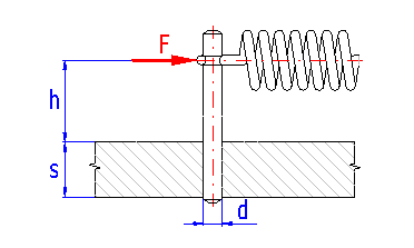
Loading with transversal bending force. The connection is checked for contact surface deformation and pin bending.
Pin bending stress:

Contact pressure:

where:
Mb ... bending moment [Nmm, lb in]
Wb ... section modulus in bending [mm3, in3]
Pb ... bending deformation [MPa, psi]
Pp ... pressure deformation [MPa, psi]
F .... acting force [N, lb]
s .... thickness of board [mm, in]
h .... arm of force [mm, in]
d .... pin diameter [mm, in]
KSb, KSp ... service factor (see details in [2.7,
2.8])
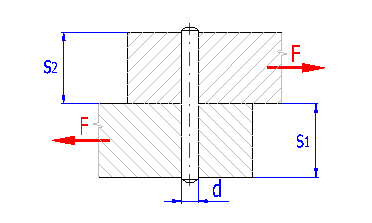
Loading with transversal shearing force. Connection is checked for contact surface deformation and pin shearing.
Pin shearing stress:

Pressure on bottom board:

Pressure on top board:

where:
F .... acting force [N, lb]
s1 ... thickness of bottom board [mm, in]
s2 ... thickness of top board [mm, in]
d .... pin diameter [mm, in]
i ..... number of pins
KL ... load distribution factor (see details in [2.6])
KSb, KSp ... service factor (see details in [2.7,
2.8])
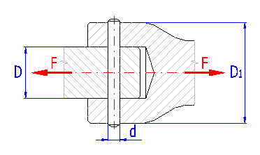
Loading with transversal shearing force. The connection is checked for contact surface deformation and pin shearing.
Recommended coupling dimensions:
d » (0.2 .. 0.3) D
D1 » (1.5 .. 2) D
- for steel hub
D1 » (2.5) D
- for cast-iron hub
Pin shearing stress:

Pressure on rod:

Pressure on sleeve:

where:
F .... acting force [N, lb]
D .... rod diameter [mm, in]
D1 ... sleeve diameter [mm, in]
d .... pin diameter [mm, in]
i ..... number of pins
KL ... load distribution factor (see details in [2.6])
KSb, KSp ... service factor (see details in [2.7,
2.8])
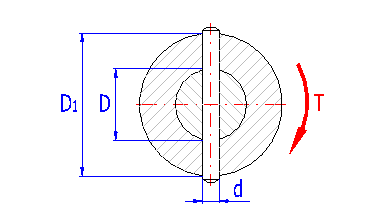
Loading with torsional moment. The connection is checked for contact surface deformation, pin shearing and shaft twisting.
Recommended coupling dimensions:
d » (0.2 .. 0.3) D
D1 » (1.5 .. 2) D
- for steel hub
D1 » (2.5) D
- for cast-iron hub
Pin shearing stress:

Pressure on shaft:

Pressure on hub:

Shaft torsional stress:

where:
T .... torque [Nmm, lb in]
D .... shaft diameter [mm, in]
D1 ... hub diameter [mm, in]
d .... pin diameter [mm, in]
KSb, KSp ... service factor (see details in [2.7,
2.8])
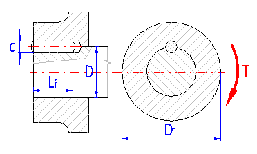
Loading with torsional moment. The connection is checked for contact surface deformation, pin shearing and shaft twisting.
Recommended coupling dimensions:
d » (0.125 .. 0.2) D
Lf » (1 .. 1.5) D
D1 » (1.5 .. 2) D
- for steel hub
D1 » (2.5) D
- for cast-iron hub
Pin shearing stress:

Pressure on shaft and hub:

Shaft torsional stress:

where:
T .... torque [Nmm, lb in]
D .... shaft diameter [mm, in]
D1 ... hub diameter [mm, in]
d .... pin diameter [mm, in]
Lf ... functional length of pin [mm, in]
i ..... number of pins
KL ... load distribution factor (see details in [2.6])
KSb, KSp ... service factor (see details in [2.7,
2.8])
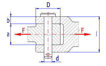
Loading with transversal bending force. The connection is checked for contact surface deformation, pin bending and shearing.
Recommended coupling dimensions:
a » (1.5 .. 1.7) d
b » (0.3 .. 0.5) a
l » (2 .. 2.5) d
D » (2.5) d
- for steel
D » (3.5) d
- for cast-iron
Pin bending stress:

Pin shearing stress:

Pressure on rod:

Pressure on clevis:

where:
Mb ... bending moment [Nmm, lb in]
Wb ... section modulus in bending [mm3, in3]
F .... acting force [N, lb]
a .... rod width [mm, in]
b .... clevis width [mm, in]
d .... pin diameter [mm, in]
KSb, KSp ... service factor (see details in [2.7,
2.8])
The typical connection calculation / design includes the following steps:
In this section, it is necessary to enter the basic initial parameters which characterize the method, mode and magnitude of load, connection design and materials of parts to be connected.
In the selection list, choose the desired calculation unit system. All values will be recalculated immediately after switching to other units.
Select the required connection type by clicking the switch by the pertinent picture.
Enter the power which will be transferred by the shaft.
Enter the shaft speed.
The transferred power and speed provide a torsional moment, which is the
basic input value for the design of the coupling.
Enter the maximum transversal force loading the connection.
Select such loading method which best suits your specification.
Select the required pin type from the list. Grooved pins do not require precise hole fitting and are more resistant to release. On the other hand, they are not suitable for connections that are dismantled frequently, or for connecting aluminium parts.
Select the required pin fitting method from the list. In running fitting methods there are considerably lower values of allowable pressures in materials used (see [1.13, 1.18, 2.9]).
With regards to accuracy and credibility of input information, importance of the coupling, quality of production and accuracy of the calculation, it is usually chosen in a range from 1.5 to 3.
From the list, select the type of material from which the connected parts will be produced. The value in brackets shows the minimum tensile strength [MPa/ksi] of the given material group. In case the checkbox to the right of the selection list is enabled, the necessary strength parameters for the chosen material are determined automatically. Otherwise, fill in the material characteristics manually. The permitted pressure values [1.16, 1.21] are used to check contact surfaces for deformation in fixed connections. In rotating connections, the permitted pressures [1.17, 1.22] are considerably lower (by up to 80%). In connections stressed with torsional moment, the permitted torsional stress data [1.23] serves to check the shaft strength for torsion.
This section serves to select a suitable pin and to propose connection dimensions.
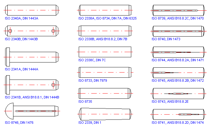
Select the pin design (standard) from the list. Standardized pins have precise diameters and lengths prescribed in the standard. Pin dimensions according to ANSI are defined in the standard in [in]; dimensions of other pin types are defined in [mm].
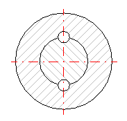
More pins can be used to transfer higher loads. Their arrangement will depend on the general connection design and/or load character. A symmetrical arrangement (shifted by 180°) is usually used in longitudinal pins on shafts.
Due to manufacturing and assembly inaccuracies, uniform load distribution among pins may not always be achieved in connections with more pins. The actual connection bearing area is then lower than that set theoretically. The ratio between the theoretical and actual load bearing surface of the coupling is defined by the coefficient of distribution of the loading. In consideration of the connection design and pin fitting accuracy and number, the coefficient value is given from 0.5 to 1.
This refers to the overall effect of manufacturing and operational parameters upon connection loading capacity reduction in terms of allowable deformation of contact surfaces. Its value depends on the pin type and connection loading character. With regards to the mentioned parameters, the literature gives values of the coefficient in a range from 1 to 3.
This refers to the overall effect of manufacturing and operational parameters upon reduction of the loading capacity of a pin loaded with shearing or bending stress. Its value depends on the pin type and connection loading character. With regards to the mentioned parameters, the literature gives values of the coefficient in a range from 1 to 3.
From the list, select the type of material from which the pin will be produced. The value in brackets shows the minimum tensile strength [MPa/ksi] of the given material group. In case the checkbox to the right of the selection list is enabled, the necessary strength parameters for the chosen material are determined automatically. Otherwise, fill in the material characteristics manually. The value of the permitted pressure [2.12] is used to check the pin for deformation in fixed connections. In rotating connections, the permitted pressure [2.13] is considerably lower (by up to 80%).
This section serves to propose connection dimensions. When designing the connection, first enter the dimensions of the parts to be connected [2.17, 2.18] and select a suitable pin diameter from the list [2.21]. For such designed connection, the minimum functional pin length is calculated in line [2.24]. Finish the connection design by selecting the actual pin length in line [2.23]. Select length from the standardized range [2.22] so that the functional length [2.25] is greater than the minimum length [2.24].
To facilitate design preparation, the program is equipped with the function of automatic selection of a suitable pin. After pressing the "Search" button, the program selects a suitable pin of minimum dimensions. The buttons "<", ">" serve to quickly change (select) pins within the standardized dimensional line of diameters. After selecting the pin diameter, the program automatically sets its optimum length.
Select the pin diameter from the standardized dimensional line of diameters. The selection of a suitable diameter can be facilitated by the recommended values [2.19] set empirically on the basis of the dimension [2.17].
The minimum and maximum allowable lengths of the selected pin prescribed in the standard.
Select pin length from the standardized range [2.22] so that the functional length [2.25] is greater than the minimum length [2.24].
In connections with longitudinal pins, this parameter gives the minimum functional length of the selected pin necessary for safe transfer of the entered torsional moment. In other types of pinned couplings, the minimum length is given by the connection design and by the dimensions of the parts to be connected [2.17, 2.18].
The functional length of the pin is the total length reduced by the pin end chamfer or round-off. In clevis pins, the active length is the distance between the clevis pin head and the cotter pin hole.

Pinned couplings are sized, under simplified assumptions, without allowing for the pressing effect and with reasonably reduced allowable stress. Connected parts are checked for deformation of contact surfaces on the hole face. Pins and clevis pins, depending on the connection type, are checked for shearing or bending stresses. As a rule, an additional check for shaft torsional stress is done in torque-loaded shaft-hub connections.
The resulting connection safety [3.4] is given by the ratio between the permitted pin material shearing stress and the calculated comparative stress. If the coupling is to be sufficient, the calculated safety must be higher than the required one [1.12].
The resulting connection safety [3.8] is given by the ratio between the permitted pin material bending stress and the calculated comparative stress. If the coupling is to be sufficient, the calculated safety must be higher than the required one [1.12].
The check for deformation is carried out separately for every part being connected. The resulting safety [3.12, 3.16] is given by the ratio between the permitted pressure of the lower quality material (of the pair pin – the part being connected) and the calculated comparative pressure acting on the given connection part. If the coupling is to be sufficient, the calculated safety must be higher than the required one [1.12].
The resulting connection safety [3.20] is given by the ratio between the permitted torsional stress of the shaft material and the calculated comparative stress. If the coupling is to be sufficient, the calculated safety must be higher than the required one [1.12].
Information on options of 2D and 3D graphic outputs and information on cooperation with 2D and 3D CAD systems can be found in the document "Graphic output, CAD systems".
Information on setting of calculation parameters and setting of the language can be found in the document "Setting calculations, change the language".
General information on how to modify and extend calculation workbooks is mentioned in the document "Workbook (calculation) modifications".