The calculation is designed for geometrical and strength designs of belt transmissions using V-belts. The application provides solutions of the following tasks
Calculation for 2 or 3 pulleys.
Automatic design of a transmission with the minimum of input requirements.
Design and calculation of geometrical parameters (diameters of pulleys, axis distances, length of the belt, weight of the transmission)
Calculation of strength parameters (power transferred by the belt, number of belts, efficiency, etc.)
Calculation of force conditions (prestressing, axis loading of the pulleys, etc.)
Support of 2D and 3D CAD systems.
The application works with CAD systems and includes respective models of pulleys and belts. The calculations use procedures, algorithms and data from basic documents and standards ANSI, RMA (Rubber Manufacturers Association), ISO, DIN, BS, and basic documents from catalogues of companies CONTITECH (r) and Gates Rubber Company (r).
List of standards: Narrow V-Belts ANSI/RMA IP-22; Traditional V-Belts ANSI/RMA IP-20; Light Duty V-Belts ANSI/RMA IP-23; DIN 7753; DIN 2211; DIN 2215; ISO 4184
![]()
User interface.
![]()
Download.
![]()
Purchase, Price list.
Information on the syntax and control of the calculation can be found in the document "Control, structure and syntax of calculations".
The calculation is designed for geometrical and strength designs of belt transmissions using V-belts. Both designs are similar to each other, therefore they will be described simultaneously and the differences will be noted in the text. In case of a reference to paragraphs, there will be a reference for a design of 3 pulleys before the slash sign and a design of 2 pulleys after the slash sign, e.g. [1/4].
Information on the purpose, use and control of the paragraph "Information on the project" can be found in the document "Information on the project".
Typical calculation / design of a transmission using a V-belt consists of the following steps:
Enter power parameters of the transmission (transferred power, speed).
Set the mode of loading and operational parameters (type of drive, length of operation, efficiency, etc.).
Fine-tune geometric parameters of the transmission "manually". (axis distances, diameters of pulleys and length of the belt) in rows [2.3-2.7/6.3-6.6]
Check power conditions of the transmission. [3/7]
Save the workbook with the designed solution under a new name.
Each change of any parameter means immediate recalculations of the whole transmission; this enables fast evaluation of many alternatives and selection of the optimum design.
Power and operational parameters of the belt transmission can be entered in this paragraph. Recommended and min./max. ranges of values are given for each parameter. If you wish to design a transmission exceeding the recommended ranges, it is advisable to consult the producer (supplier) of the belts (pulleys).
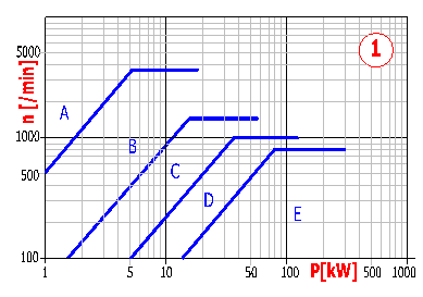
Usually it is possible to transfer power from several tenths up to hundreds of kW/HP. The optimum range is from 1 to 100kW / 1.4 to 140HP. More detailed information can be found in power diagrams of V-belts in paragraph [2.1/5.1] or in catalogues of producers.
In case of 3 pulleys, it is also necessary to define the power withdrawn by the third pulley in addition to the power transferred at the input (pulley no. 1). The value of the withdrawn power on the second pulley is then calculated additionally using these two values.
The speed defines the transmission ratio, which is then used in the calculation. Pulley no. 1 is the driving pulley. The limit values of the maximum speed are defined for individual types of V-belts (lower power -> higher speed and vice versa) and in extreme cases the speed should not exceed a value of 8000 rpm. These values can usually be found in a range from 400 to 3000 rpm of the driving shaft. However, more important is the value of the peripheral speed than the speed itself, see paragraph [3.10/7.10]. More detailed information can be found in power diagrams of V-belts in paragraph [2.1] or in catalogues of producers.
It is calculated additionally using the input speed and desired output speed. The value of the transmission ratio should usually not exceed the maximum value i=8, in extreme cases values up to i=15 can be reached.
The value of the torque is calculated additionally for each pulley using the speed and power.
Select the manner of loading which best meets the requirements of the entered specifications.
Select the manner of loading which best meets the requirements of the entered specifications.
Here the number of hours of operation of the belt transmission per day can be set.
A flexible slipping of the belt in the belt groove occurs in case of a belt transmission operated under a load. This slipping depends on the loading of the transmission and increases with growing loading. The slipping is expressed by the "Coefficient of slipping" in % and in case of V-belts, its value is around 1%. The coefficient of slipping does not affect the transmission ratio. The calculated (recommended) theoretical value is given in the green field. If the check mark box is enabled, the calculated (recommended) value is filled in automatically and used in the calculation.
Losses in the transferred power occur, above all, due to friction in belt transmissions. These losses are expressed as efficiency, which increases with growing loading and in case of a usually loaded transmission using a V-belt (two pulleys), it varies between 95 and 97%. However, in case of great differences in diameters of the pulleys (small angle of wrapping, high wear) it may decrease down to 80%. The calculated (recommended) value is given in the green field and enabling of the check mark box means that the calculated (recommended) value is used in the calculation automatically.
Before initiation of the "Automatic design" enter (select) all parameters in this paragraph [1/4]. When making decisions, use the help and recommendations given with each parameter. The automatic design selects a suitable type of belt on the basis of the transferred power and speed and initiates the "Optimizing process" for this type of belt. Naturally, an automatically designed solution is possible and mostly it is also advisable to "fine-tune" it manually.
The geometry of the belt transmission can be designed in this paragraph. It is possible to choose the type of belt, diameters of pulleys, axis distances and lengths of the belt.
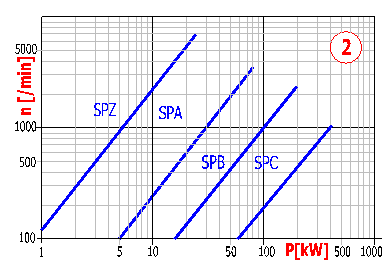
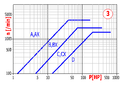
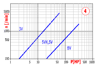
The recommended type is selected on the basis of the transferred power and speed. As another guideline for selection of the correct type of belt, power diagrams specifying fields for use of the particular type of the belt may be used. The diagrams 1 and 2 are designed for belts according to ISO (DIN, BS), diagrams 3 and 4 for belts according to ANSI/RMA. The minimum recommended diameter is automatically substituted into the smallest pulley after selection of the belt. Diameters of other pulleys are calculated additionally to obtain the desired speed.
In the selective list, select the type of V-belt which has to be used (the Automatic design performs the selection itself). The smallest recommended diameter of the pulley is selected automatically and used after selection of the type of the belt. The other two (one) diameter(s) are calculated additionally according to the desired speed.
The optimizing process [2.2/6.2] passes through table diameters of the driving pulley for the selected type of belt, performs a design of the optimum axis distance, calculates additionally all other parameters and tries to find a design with the minimum total weight [2.12/6.12]. The optimizing process can be initiated using the button "Optim".
Selective lists include calculating diameters of pulleys from the tables. Outer diameters of pulleys (if mentioned) are given in parenthesis.
This row includes the diameters of pulleys which are used in the calculation. It is possible to enter directly only the diameter of the first pulley. The diameter of the second (third, resp.) pulley is calculated automatically on the basis of the desired Output speed [1.2] and the Coefficient of slipping [1.8]. If you wish to use standardized (table) diameters with all pulleys, proceed as follows:
The rows indicate the minimum (constructional aspect) and maximum (recommendation) values of axis distances between the pulleys. These pieces of information, together with the optimum axis distance, are given in row [6.4] for purposes of calculation of the transmission.
In the row enter the desired axis distances between the pulleys. Each change in axis distance is checked and if you enter an incorrect value, the remaining axis distances are modified automatically.
The enabled (activated) check mark box means that the marked axis distance will be locked for any change (if possible, constructionally) in case of modifications to axis distances with calculations to obtain the table length of the belt [2.7]. The unmarked axis distance will be changed with the recalculation.
The actual working length of the belt can be found in the first column. The second column includes the minimum possible length (for the given diameters and minimum axis distances). The third column provides a selective list with standardized (table) lengths of the belt (inner length and in parenthesis, the calculating length). After selection of a suitable length of belt, the marked axis distances [2.6] are changed iterationally to obtain the desired length of belt. The button "R" to the right of the selective list repeats iteration for the actual selected length of the belt.
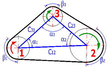
This is the angle formed by straight lines running through centres of the pulleys - see the illustration.
It is an important parameter on which the power transferred by one belt is substantially dependent. The angle should not be smaller than 90° in case of pulleys which transfer some power.
It is the real power which the given belt is able to transfer to the pulley under the given conditions (constructional arrangement, loading mode, and operational parameters). Basic power parameters of the belt can be obtained from power tables (ISO, DIN, BS, CONTITECH (r)) or from power formulas (ANSI/RMA and Gates Rubber Company (r)) using interpolation.
This gives the exact number of belts necessary to transfer the desired power for the given pulley.
The necessary number of belts is the highest value from the previous row rounded to the nearest higher integer. The number of belts should not be higher than 10 under standard conditions.
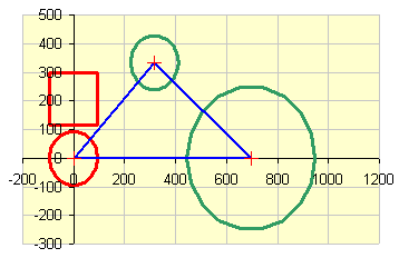
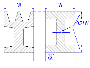
The approximate weight is the sum of the weight of pulleys and belts of the actual transmission. The weight of the pulleys is calculated approximately according to the illustration. Cast iron is considered as the default material. Despite the fact that the weight cannot be exactly the same as the final weight of the pulleys, it is a good optimizing parameter which should be taken into account in the design.
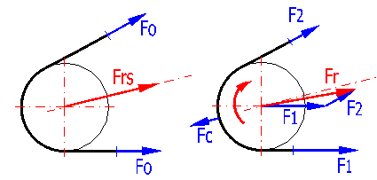
Some coefficients used for the calculation can be found in this paragraph. Above all, this paragraph includes force conditions acting on the pulley.
These coefficients affect the power transferred by one belt.
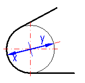
The axis of one of the pulleys of the designed belt transmission must be adjustable. Row [3.6, 3.7] provides minimum values for each pulley, namely values for tension of the belt (parameter x) and for installation of the belt (parameter y). The shift is calculated for the axis halving the angle formed by the strips of the belt on the given pulley.
As the belt transmissions show the highest mechanical efficiency at full loading and in the course of operation, the value of the prestressing decreases (unless constructionally secured otherwise), this calculation implements this coefficient of safety, which increases values of prestressing of the belt. The recommended value of this coefficient is between 1.1 and 1.3 and is given in the green field. If the check mark box is enabled, the recommended value is substituted automatically.
The peripheral speed of the belt is another important parameter of the belt transmission. The optimum peripheral speed for V-belts is about 25 [m/s] / 5000[ft/min]. The maximum speed varies for various types (producers) of V-belts and is given in the green field.
It is dependent on the type of belt. Detailed information can be found in the producer's catalogue. Maximum values can be found in a range from 50 to 100 [/s].
It is a basic force derived from the transferred power and the speed of the belt.
The component of centrifugal force is applied only at higher speeds of the belt (approx. at 20 [m/s] / 4000 [ft/min]).
"Prestressing" of the belt, which provides sufficient friction forces and is needed for transfer of the desired power, is necessary for correct functioning of the belt transmission.
The force which acts on the shaft at rest.
These are the forces which act in operation in the loaded (and relieved resp.) parts of the belt.
This force acts in operation on the shaft of each pulley. It needs to be known for dimensioning of shafts, bearings and other constructional elements of the belt transmission.
This paragraph provides dimensions of the selected belt and dimensions of each pulley. These dimensions are used for 2D drawings and 3D models. Tolerances of dimensions and other supplementary information can be found in the respective standard or in the producer's catalogue.
After installation and tensioning of the belt (ensured using axis adjustability of one of the pulleys or a tension pulley) it is necessary to perform a check of tension of the belt. As producers of belts use various procedures and also deliver instruments for checks of tension of the belt, customers interested in purchasing these instruments are referred to company catalogues and procedures.
Information on options of 2D and 3D graphic outputs and information on cooperation with 2D and 3D CAD systems can be found in the document "Graphic output, CAD systems".
As this workbook includes two types of calculations (for 2 or 3 pulleys), the following switches extend the standard options for creation of 2D drawings.
In the selective list, select whether to use, for creation of a 2D drawing (3D model), the dimensional data from the calculation of 3 pulleys or 2 pulleys.
In the selective list, select the pulley which has to be drawn in a detailed view.
The angle sets angular rotation of the drawing of the set of pulleys in relation to the horizontal axis (illustration - see the pushbutton).
Information on setting of calculation parameters and setting of the language can be found in the document "Setting calculations, change the language".
Selection of a database of V-belts changes the respective power parameters of the belts. There are available:
General information on how to modify and extend calculation workbooks is mentioned in the document "Workbook (calculation) modifications".
The whole series of parameters depends on specifications of the particular producer of the respective V-belt. In fact, it is therefore possible to change in this calculation any parameter (diameters of pulleys, lengths of belts, power tables, power formulas) in tables defining dimensions and properties of the belts.
^