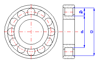
For a roller bearing assembled from three components with dimensions:
1. Outer ring - diameter D=160 mm
2. Inner ring - diameter d=120 mm
3. Rollers - diameter dr=20 mm
design the manufacturing tolerances of all components and parameters of the selective assembly so that a radial clearance ranging from 60 mm to 90 mm is kept during the bearing assembly. The bearing further requires interchangeability of the inner ring so that a radial clearance ranging from 40 mm to 105 mm is guaranteed during replacement of the ring in case of repair of the bearing.
Production of roller bearings is a typical example suitable for use of the selective assembly method. Using the traditional "Worst Case" method for the solution of the specified example will secure full assembly and working interchangeability of all components, however it would be necessary to manufacture the components of the bearing with accuracy level 3 to keep the required radial clearance. It is obvious that production with such accuracy level would be unreasonably expensive. Using the selective assembly method, the components can be made with significantly lower accuracy. The solution to the selective assembly problem itself consists of two parts:
The size of radial clearance for roller bearings is specified by the relation c = D - d - 2*dr.
The solution to the task of dimensional chain design and optimization can be divided into the following steps:
1) Using the above-mentioned relation, we will define the dimensional chain in table [7.1]. Individual components used during assembly of the bearing are partial components of the chain. The required radial clearance is then the closed component of the dimensional chain.
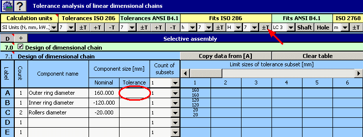
2) Next set the required manufacturing tolerances for individual dimensions. In the initial design, use tolerances at accuracy level 7 for all components. For the roller diameter, choose symmetric tolerance, H7 for the outer ring diameter tolerances and h7 for the inner ring.
3) For all components, initially set 10 tolerance subsets for the manufactured components to be sorted into.

4) In paragraph [8.1] set the requirement of working interchangeability of the inner bearing ring.
5) In paragraph [8.4] set limit sizes of the required radial clearance during assembly of the bearing and replacement of the inner ring.
6) In list box [8.9] choose search for all assembly combinations. Start the search for combinations using the button on line [8.10].
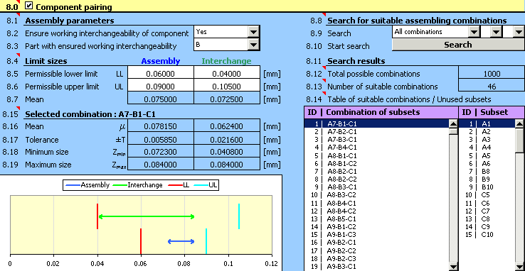
7) The design quality can be assessed from the results in paragraph [8.11]. It is obvious that in this case the design is not suitable. From the table of "Unused subsets" in line [8.14] it is clear that it was not possible to use more than half of the manufactured outer rings and rollers for assembly of the bearing.
8) For the unsuitable design, the next logical step could be decreasing the sizes of used manufacturing tolerances. On closer scrutiny of the design, however, we will find out that the main problem is not the selected size of tolerances, but rather wrong centring of the design. The standard indicator for better assessment of this design aspect is the mean dimension of the closed component calculated in paragraph [7.2].

For the optimum design of the tolerance chain, the specified dimension should be as close to the required value as possible [8.7].
9) In the repeated design, adjust the position of the tolerance field of all components while keeping the sizes of tolerances. For the outer ring diameter, use G7 tolerance, and g7 for the inner ring diameter.
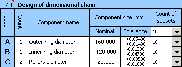
Next adjust the upper and lower deviation of the diameter of the rollers so that the resulting design is centred as well as possible.

10) For such adjusted design of a dimensional chain repeat the search for all suitable assembly combinations.
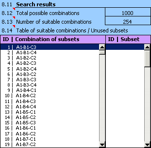
11) From the search results it is obvious that all manufactured components will be usable in the bearing assembly. However, the design is not that efficient as the number of suitable assembly combinations is unnecessarily high. We can decrease the number of suitable combinations e.g. by decreasing the number of tolerance subsets which the manufactured components will be sorted into.
12) While gradually decreasing the number of subsets, we will come to the resulting design of the dimensional chain,
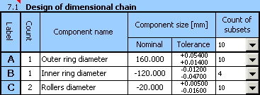
which seems optimum for the selected example.

The resulting 75 suitable assembly combinations are acceptable for the purpose of selective assembly.
In the previous part of the task we designed manufacturing tolerances of components and searched for all suitable assembly combinations which can be applied during assembly of the bearing with suitable parameters. However, during the assembly itself it is not practical to assemble the bearings by mere random choice of components within permissible assembly combinations. If the selective assembly method is to be efficient, it is necessary to solve the problem of optimum selection (combination) of components. The components have to be matched so that it is possible to assemble the maximum possible number of products which meet the functional requirements with the given number of manufactured components.
This task has to be solved repeatedly during production, whenever the stock is replenished before assembly itself is started. The main part of the task is to determine the optimum assembly procedure in order to achieve the largest possible number of assembled products. When solving the task, we have to choose the optimum set of combinations from the previously found subset of acceptable combinations used in assembly and at the same time determine the number of products assembled within each used combination.
The solution to the task of optimization of the number of assembled products is performed in the following steps:
1) In table [9.1] set the number of manufactured components in individual tolerance subsets.

2) In list box [9.3] choose a suitable optimization method. For the selected example choose "Basic method", which gives the best results. Although this method is rather slower than the other methods for the small numbers of components which the bearing should be assembled from in the given example, we can use it even on less efficient computers.
3) Select "Batch processing" in list [9.5]. After this item has been chosen, the program will gradually perform optimization for all 10 basic solutions. The most suitable solution will then be chosen with respect to the maximum assembled products and minimum used assembly combinations.

4) Press the button on line [9.5] to start optimization.
5) Basic qualitative parameters of the design procedure are specified in paragraph [9.6]

a detailed specification of optimized assembly procedure is shown in table [9.12].
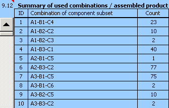
The left column of the table shows all assembly combinations used for assembly of the product. The right column shows the number of products assembled within each combination.
|
Optimization method |
Number of assembled bearings |
Number of used assembly combinations |
Speed of calculation |
|
A. Basic method |
762 |
29 |
6 min 20 s |
|
B. Modified method |
760 |
34 |
1 min 30 s |
|
C. Simplified method |
759 |
32 |
55 s |