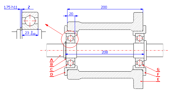
For the example of fit of the shaft in the case (see the picture), design manufacturing tolerances of individual components so that 0.05 - 0.80 mm clearance in fit is ensured. The designed tolerances have to match the following technological production requirements:
- contact areas of the case will be machined using milling
- turning will be used to machine the shaft and bearing bushings
with:
A ....... Shaft
B ....... Retainer ring 40 DIN 471
C,G .... Bearing 6308 DIN 625 SKF
D,F .... Bearing sleeve
E ....... Case
Z ....... Clearance in fit <0.05 to 0.80> mm
If we start from the dimensional chain diagram

we can describe clearance in fit for the given problem using the relation Z = A - B - C + D - E + F - G
In the design of manufacturing tolerances itself we have to proceed from the technological demands of production. The size of designed tolerances of individual components has to range within the manufacturing accuracy achievable with the selected machining method. In case of milling, commonly achieved manufacturing accuracy ranges between tolerance levels 9 and 13, in case of turning it ranges between tolerance levels 6 and 12.
We can divide the solution of the task of designing and optimization of a dimensional chain into the following steps:
1) Using the above-mentioned relation, we will define the dimensional chain in table [1.1]. Partial components of the chain are formed by individual components; required clearance in fit is the closed component of the dimensional chain.
2) In case of components with fixed tolerance prescribed by the manufacturer (bearings, retained ring), we will set the appropriate dimensional deviations in the input table.
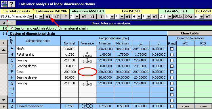
3) Contact areas of the case will be machined by milling; in the first design we will therefore select the size of tolerance at accuracy level 11 for the width of the case.
4) By checking appropriate switches in column 8 of the table, we will mark all components with fixed tolerance.
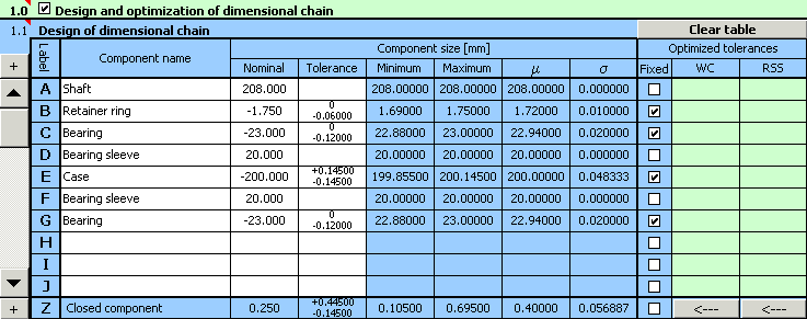
5) In paragraph [1.3] we will set limit values of the required clearance in fit.
6) In list box [1.7] select the "Centring and optimization" method, in list [1.8] choose "Standard tolerances".
7) Turning will be used to machine all components for which we want to design tolerances in the next step. In the list box [1.9] we will therefore set the minimum allowed number of tolerance to accuracy level 6.
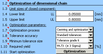
8) Using the button in line [1.11] we will start optimization of the dimensional chain.
9) Parameters of the resulting clearance achieved for the optimized design of tolerances are shown in paragraph [2.5],

optimized deviations of manufacturing dimensions are listed in column 9 of table [1.1].
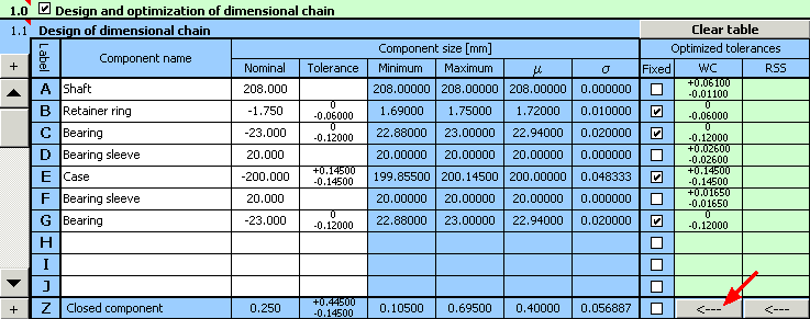
10) For the example specified herein, a functionally suitable solution was found during optimization; however from the practical point of view such design is not suitable. The program designed the width of the bearing sleeves in lines D and F with different tolerances. For the sake of production and assembly efficiency, it is necessary to secure interchangeability of both bearing sleeves. The next step in the design deals with removing this fault.
11) Use the button on the bottom table line to transfer the designed tolerances to the input part of the table, then unify the tolerance for both sleeves using the higher of the designed values.
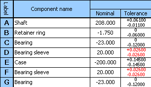
12) In column 8 of the table, further check the switches in lines D and F, and restart optimization using the button on line [1.11].

13) This time the design will result in a fully suitable solution of the problem with bearing sleeve tolerance at accuracy level 9 and accuracy level 7 for shaft tolerance.
The solution designed herein will not of course be the only suitable solution to the problem and it need not be the ideal solution either. Therefore, it is appropriate (especially in case of lot production) to design several different solutions with varying accuracy of manufacturing of individual components.
We will obtain another solution to the problem if we choose the lower of the originally designed values for the bearing sleeve tolerance in step 11).

We will obtain further suitable solutions in case of selecting a different case width in step 3). The following table shows a comparison of several suitable designs:
| Solution 1 | Solution 2 | Solution 3 | Solution 4 | |
| Tolerance grade | ||||
| Case | 11 | 11 | 10 | 10 |
| Bearing sleeves | 9 | 8 | 10 | 9 |
| Shaft | 7 | 8 | 8 | 9 |
| Clearance in fit [mm] | 0.053 - 0.793 | 0.061 - 0.789 | 0.062 - 0.788 | 0.073 - 0.777 |
The resulting solution has to be chosen so that the total manufacturing costs are as low as possible.