The calculation is designed for a geometrical design and strength check of toothed belt transmissions. The application solves the following tasks.
Selection of the type of belt with a suitable output power.
Selection of an optimum transmission alternative in view of power, geometry and weight.
Option of designing a non-standard transmission.
Calculation of all necessary strength and geometrical parameters
Calculation of power parameters and axis loads.
Support of 2D and 3D CAD systems.
The application works with CAD systems and includes the respective models of pulleys and belts. The calculations use procedures, algorithms and data from ANSI, RMA (Rubber Manufacturers Association), ISO, DIN, BS and basic documents from catalogues of companies ContiTech(r) and Gates Rubber Company(r). The database of belts includes the 20 most frequently used types of toothed belts.
User interface.
Download.
Purchase, Price list.
Information on the syntax and control of the calculation can be found in the document "Control, structure and syntax of calculations".
Information on the purpose, use and control of the paragraph "Information on the project" can be found in the document "Information on the project".
In this paragraph, set calculation units, enter power parameters and set the transmission loading mode.
In the list box, select the desired system of calculation units. All values will be recalculated immediately after switching to other units.
Enter the power demand on the driving wheel. The power to the driving wheel will be calculated according to the preset efficiency.
Enter the speed of the driving wheel and the desired speed of the driven wheel. The desired transmission ratio [1.5] is calculated. Based on the desired transmission ratio, the number of teeth of the driven pulley is designed and the actual transmission ratio and actual speed of the driven wheel is calculated retrospectively.
These are calculated using the input speed and number of teeth of the pulleys.
The desired transmission ratio is calculated using the desired input and output speed. The actual transmission ratio is calculated using the number of teeth of both pulleys.
It is calculated using the actual speed [1.4] and the transferred power [1.2]
Select the type of driving machine which best fits your task.
Electric motors with a low starting torque (up to 1.5 times the rated torque). Water and steam turbines, Internal combustion engines with 8 or more cylinders.
Electric motors with a medium starting torque (1.5 to 2.5 times the rated torque). Internal combustion engines with 4 to 6 cylinders.
Electric motors with high starting and braking torque (more than 2.5 times the rated torque). Hydraulic motors. Internal combustion engines with 4 cylinders or fewer.
Select the type of driven machine which best fits your task.
Display, Dispensing Equipment, Instrumentation, Measuring Equipment, Medical Equipment, Office Projection Equipment
Appliances, Sweepers, Sewing Machines, Screens, Oven Screens, Drum, Conical Woodworking Equipment (Light): Band Saws, Drills, Lathes
Agitators for Liquids, Conveyors: Belt, Light Package, Drill Press, Lathes, Saws, Laundry Machinery, Wood Working Equipment (Heavy): Circular Saws, Jointers, Planers
Agitators for Semi-Liquids Compressor: Centrifugal, Conveyor Belt: Ore, Coal, Sand, Dough Mixers, Line Shafts, Machine Tools: Grinder, Shaper, Boring Mill, Milling Machines, Paper Machinery (except Pulpers): Presses, Punches, Shears, Printing Machinery, Pumps: Centrifugal, Gear, Screens: Revolving, Vibratory
Brick Machinery (except Pug Mills), Conveyor: Apron, Pan, Bucket, Elevator, Extractors, Washers, Fans, Centrifugal Blowers, Generators & Exciters, Hoists, Rubber Calender, Mills, Extruders
Centrifuges, Screw Conveyors, Hammer Mills, Paper Pulpers, Textile Machinery
Blowers: Positive Displacement, Mine Fans, Pulverizers
Compressors: Reciprocating, Crushers: Gyratory, Jaw, Roll Mills: Ball, Rod, Pebble, etc. Pumps: Reciprocating Saw Mill Equipment
The design of the value "Coefficient of operational loading" is based on parameters
[1.7], [1.8] a [1.9]. If the check box is enabled, the designed value is used in the calculation automatically.
The type of belt can be selected in this paragraph. For the selected belt there may then be initiated "Automatic design"(recommended), which selects the optimum alternative of pulleys, widths and lengths of belts to provide the most effective design. A manual calculation can be executed in paragraph [3].
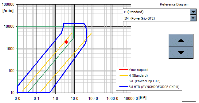
Select the belt from the list box. The power graph shows the working area of the selected belt (speed vs. power) in blue. The graph shows a red "cross hair", which gives the actual requirement (entered power and speed) for the designed transmission. The cross hair should be found within the working area of the selected belt. Basic types of toothed belts, their use can be found below.
It is a theoretical distance available using minimum/maximum length of the belt and the corresponding pulleys. The actual minimum / maximum and the recommended axis distance corresponding to the selected pulleys can be found in row [3.5].
Enter here the axis distance which has to be reached.
Pressing the button "Automatic design" initiates the process of automatic design. The displayed index shows the design procedure.
The results in the table of designs can be re-classified at any time by using another criterion selected from the pop-up list.
When using the "Automatic design", all possible combinations of pulleys and belts are processed and all designs which approach the desired criteria (transmission ratio, axis distance, strength) are entered in the table of designs. The designs are classified according to the criterion selected in row [2.5].
After completion of the process "Automatic design" the design whose coefficient of utilisation of the belt is closest to 1 is selected. If the automatic design is not suitable, select from the table (pop-up list) such design which best fits your requirements.
The table of designs includes the following values:
| Symbol | Description |
| z1 | Number of teeth of the driving pulley. |
| z2 | Number of teeth of the driven pulley. |
| B | Belt width. |
| i | Transmission ratio. |
| di [%] | Percentage deviation of the achieved transmission ratio from the desired one. |
| A | Axis distance. |
| dA | The deviation of the achieved axis distance from the desired one. |
| SF | Coefficient of belt utilisation. |
| m | Approximate total weight (both pulleys + belt). |
The calculation of the belt transmission can be found in this paragraph. All input parameters can be changed in this paragraph. The resulting values are calculated immediately after any change.
The pop-up list includes the available widths of the selected type of belt. Select the desired width.
The pop-up list includes the available diameters of pulleys for the given type and selected width of belt. The option sets the number of teeth (diameter) of the driving pulley in the following row[2.12].
Enter the number of teeth of the driving pulley (unless entered from the pop-up list in the previous row). The number of teeth of the driven pulley is calculated on the basis of the desired speed, and the most suitable pulley is selected from the list of available pulleys.
The pitch diameters of both pulleys Dp are calculated using the pitch and number of teeth.
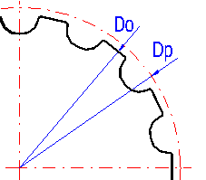
The first cell gives the recommended axis distance, the second cell gives the range from the minimum to the maximum recommended axis distance.
Enter the desired axis distance of pulleys here. The actual axis distance (of the selected pulleys and the most suitable table length of the belt) is calculated immediately after entering (change) the desired axis distance. This calculation is executed if the check box in row [3.8] is enabled.
The pop-up list includes the numbers of teeth and available lengths of a belt for the given type and selected width. The selection sets the number of teeth (length) of the belt in the following row[2.17] and disables the check box in row [3.8].
The optimum number of teeth of the belt is designed in the cell on the right. The design is based on the desired axis distance, selected pulleys and available lengths of the belt. If the check box is enabled, the design value is transferred automatically to the cell on the left and thus to the calculation as well. If you wish to enter your own number of teeth of the belt /different from the designed number), disable the check box and enter the value in the cell on the left.
The length of the belt is calculated using the number of teeth and spacing.
The "Design power" is calculated using the desired transferred power and the manner of loading of the transmission. The toothed belt is dimensioned to this power.
It is the actual power which the selected belt is able to transfer under the given conditions (constructional arrangement - diameters of pulleys, axis distance). The basic power parameters of the belt are obtained using power equations of the belt.
The approximate weight is the sum of estimated weights of both pulleys and the belt. Cast iron is considered the default material. Despite the fact that the weight cannot correspond exactly to the final weight of the pulleys, it is very good optimising parameter which should be taken into account with the design.
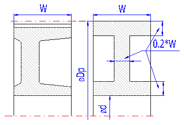
The weight of the pulleys is calculated according to the simplified illustration on the right.
It is the quotient of the "Design power" and the "Power transferred by the belt". The optimum value of the coefficient should be lower than 1 and as close to 1 as possible. If the coefficient is higher than 1, it may cause shortening of service life and even destruction of the belt.
The switch tells the calculation whether the pulleys have to be selected from the range of table (produced) values.
The switch tells the calculation whether the pulleys have to be selected from the range of table (produced) values.
The coefficients used for calculation can be found in this paragraph. This paragraph also includes force conditions acting on the pulley. The force conditions are shown in the illustration in the lower part of this paragraph.
These coefficients are based on loading of the belt, the type of belt and the constructional arrangement of the transmission. It is advisable to consult specialized or company literature for details.
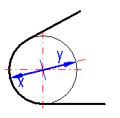
In case the belt transmission does not include any tightening pulley, the axis of one of the pulleys should be adjustable (for installation and tightening of the belt). The given values are informative and given for a pulley without guide flanges. The particular values can be found in company documentation.
Row [3.10, 3.11] shows minimum values for each pulley, more precisely for tightening of the belt (parameter x) and for installation of the belt (parameter y).
Peripheral speed of the belt is another important parameter of the belt transmission. The given maximum value of the peripheral speed is informative and if the peripheral speed reaches or exceeds these values, it is advisable to consult specialists of the producer.
Three procedures are available for calculation of forces acting in the transmission. The firs common procedure - can be used for standard trapezoidal toothing (MXL, XL, L, H, XH, XXH). The other two procedures are according to company literature of the respective producers.
The general calculation is based on the fact that in most cases, toothed belts work best if force F2 in the relieved part of the belt is equal to 10-50% of tensile force Fu (the quotient of the torsional moment and the pulley radius). The size of this force is affected by a series of factors and the recommended percentage value is given in row [4.15]. Automatic transfer of the recommended value to the calculation is activated by enabling the check box.
Other force values are then calculated using the selected force F2. For the meaning, see the illustration.
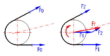
This force is the resultant force acting on the pulley. It needs to be known for dimensioning of shafts, bearings and other constructional elements of the belt transmission.
"Prestressing" of the belt is necessary for correct functioning of the belt transmission, as this prevents deflections of the relieved part of the belt and ensures correct engagement of the teeth of the belt with the pulley. The correct amount of prestressing is mostly found out by measurement of deflection t at the point of acting of force F on the belt (see the illustration). Measuring instruments, the measurement procedure and values are available in manuals from producers of the belts.
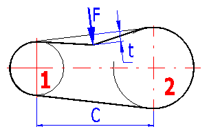
This paragraph gives basic dimensions of the selected belt and dimensions of each pulley. These dimensions are used for 2D drawings and CAD models.
Historically, a series of types of synchronous belts was developed by several producrs. Therefore, the following general table of synchronous belts, power limits and types of use is given here. Particular parameters of the belts may differ depending on the producer.
The first ever developed type of synchronous belt. Can be used in older or hereditary constructions. It is not possible to achieve today's technical level, accuracy, minimum dimensions and price if used in new constructions.
Profile:
Dimensions: MXL, XL, L, H, XH, XXH (inches) T2.5, T5, T10 (mm)
Powers: up to 150kW | 200HP; up to 10,000 rpm; up to 40m/s | 8,000ft/min
Improved type of synchronous belt. Applicable in a wide range of powers and speeds.
Profile:
Dimensions: (HTD) 3M, 5M, 8M, 14M, 20M
Powers: up to 1000kW | 1350HP; up to 20,000 rpm; up to 80m/s | 16,000ft/min
Other improvements in synchronous belts. These show higher specific transferred powers, higher accuracy and lower noise.
Profiles:
Dimensions: (GT, GT2, STD) 2M, 3M, 5M, 8M, 14M
Powers: up to 600kW | 800HP; up to 20,000 rpm; up to 80m/s | 16,000ft/min
Obviously, the most important types derived from the most widespread basic types are:

Catalogues of producers include other special types for various specific purposes.
Information on options of 2D and 3D graphic outputs and information on cooperation with 2D and 3D CAD systems can be found in the document "Graphic output, CAD systems".
Information on setting of calculation parameters and setting of the language can be found in the document "Setting calculations, change the language".
General information on how to modify and extend calculation workbooks is mentioned in the document "Workbook (calculation) modifications".
A series of parameters depends on specifications of the particular producer of the respective toothed belt. In principle, user's changes and settings of any parameter in the database of belts used in the calculation are therefore possible.
All parameters of available belts are given in the sheet "Tables", which is accessed by clicking on the tab with the name of the sheet in the lower part of the book. The calculation's basic data are saved in the table "Belt types", where each row corresponds to one belt type. The rows of the table are provided with particular descriptions for simple orientation.
^