The calculation is intended for the purposes of geometric and strength designs of spiral cylindrical torsion springs made of wires and rods in circular sections, exposed to a static or cyclic loading. In addition to the design of geometric and strength parameters, the calculation works with CAD systems. The application provides solutions for the following tasks:
Automatic design of the spring.
Selection of the optimal design of the spring with respect to strength, geometry and weight.
Static and dynamic strength tests.
Calculation of the working forces of a spring with known production and mounting dimensions.
Calculation of mounting dimensions for known spring loading and production parameters.
The application includes a table of commonly used spring materials according to ISO, EN, ASTM/SAE, DIN, BS, JIS and others.
Support of 2D and 3D CAD systems.
The calculation is based on data, procedures and algorithms from specialized literature and the standards EN 13906-2, and DIN 2088.
User interface.
Download.
Purchase, Price list.
Information on the syntax and control of the calculation can be found in the document "Control, structure and syntax of calculations".
Information on the purpose, use and control of the paragraph "Information on the project" can be found in the document "Information on the project".
A torsion spring is a spiral cylindrical spring with approximately constant angle (moment) stiffness that is able to receive external forces acting perpendicularly to the axis of the coiling with a torsional moment in the direction of coiling or uncoiling. In the view of the spring function there are four basic states of springs:
| State of the spring | Description of the spring state | index |
| free | the spring is not loaded | 0 |
| preloaded | the spring is exposed to the minimum operational loading | 1 |
| fully loaded | the spring is exposed to the maximum operational loading | 8 |
| limit | the spring is exposed to terminal loading | 9 |
The above mentioned indexes are used in the calculation to specify the individual parameters of the spring, related to the given state of the spring.
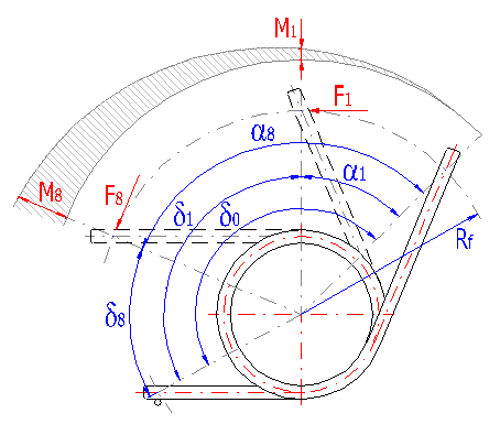
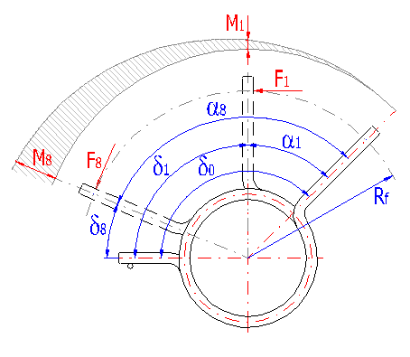
The calculation of the torsion spring used here does not take into account the effects of supporting of the spring against the inner or outer guiding part, nor the effects of friction that appears with it. The effects of possible friction between the coils of the spring are also not considered.
The task of the spring design cannot be solved directly and allows a considerable amount of freedom in the options of the design, dimensions or loading of the spring. Many springs of various designs and dimensions may meet the requirements of the desired input parameters of the task. Therefore, it is necessary to proceed iteratively and to successively evaluate the individual designs of the spring. The calculation solves this problem by creating a table outlining the optimum designs for the chosen qualitative standard. The solution procedure is given in the following items (the square brackets indicate the number of the paragraph).
In this paragraph, enter the basic input parameters, characterizing the method and mode of loading, design and method of setting the spring and the parameters of the working environment.
Two basic ways of loading springs are available for the purposes of calculating the springs:
The temperature of the operational environment affects the relaxation of the spring, appearing as a reduction of the force developed by the spring with its deformation moving to a constant angular deflection of the legs depending on time. It is advisable to take this fact into account with the design of the spring and increase the level of safety in a proper way with strength tests on the spring for temperatures over 80 °C. The operational temperature must also be reflected in the selection of the spring material.
The service life of the springs decreases significantly due to corrosion effects. Corrosion has very strong effects, particularly on springs exposed to a fatigue loading. It is advisable to take this fact into account with the design of the spring and increase the level of safety in a proper way with strength tests on the spring in a corrosion-aggressive environment. It is also necessary to consider the corrosion effects with the selection of the spring material.
With spiral springs, the stress, appearing in the spring coil at the given load point, is calculated for a simple torsion for the central spoke of the coil. The actual stress in the extreme fibres of the coil is substantially higher, above all, due to the curving of the coil. Therefore the stress is corrected in the calculation using a correction coefficient. As several different coefficients are commonly used, please choose the correction coefficient from the list that meets your requirements or recommendations of standards.
Torsion springs are produced in two basic designs: tight-coiled and loose-coiled (with clearance between the coils). If the springs are exposed to a fatigue loading, the tight-coiled springs are recommended. However, if friction appears between the coils of these springs while they are working, this may cause the service life of the springs to decrease. In addition to this, the close distance of the coils prevents perfect shot peening of the spring. Therefore loose-coiled springs are used when a service life longer than 105 working cycles is required. The pitch of the spring is usually in the range of 0.3*D < t < 0.5*D.
where:
D - mean diameter of the spring
t - pitch of the spring
It is advisable to design the torsional springs so that they are loaded in the direction of coiling, i.e. they coil themselves when receiving energy and uncoil when releasing energy. If it is technically necessary to load the spring against the direction of coiling, it is advisable to design the spring with a higher level of safety (approx. by 3-5%).
The shot peening of the spring increases the fatigue limit in the spring by approx. 10 to 15%. If springs with shot peening are exposed to a fatigue loading, this allows you to reduce its dimensions and installation space, increase the angle of its working stroke or increase the security of the spring against fatigue breaks. Therefore, it is advisable to apply the technical requirement of shot peening to all springs exposed to an oscillating load. Due to technological reasons, only springs with diameters of wire over 1 mm are shot peened.
The clockwise direction (in a dextral helix) is preferably used with springs; the counterclockwise direction is used only if technically necessary.
With torsion springs, the moment of the force is usually transferred using the legs. The working leg of the spring is meant as the loaded leg, which rotates around the spring axis in the direction of the acting force while the load is applied on the spring. The supporting leg keeps its position while the load is applied on the spring.
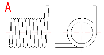
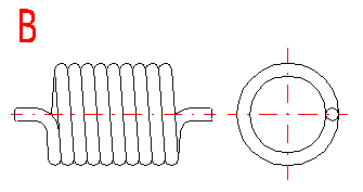
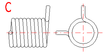
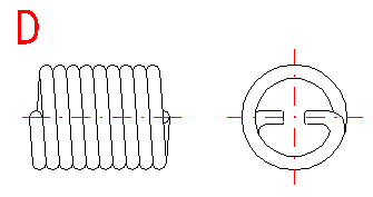
With regards to the possible occurrence of stress concentrations, the shape of the legs of the torsion spring should be as simple as possible. The basic types of legs used with torsion springs are given in a list that can be used to choose a suitable solution according to the illustration. The option of the leg design depends on the desired method of setting the spring, its dimensions and desired distance of the loading application point from the spring axis, while the supporting and working legs of the spring may be different.
Basic types of legs:
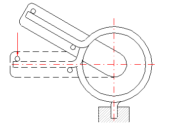
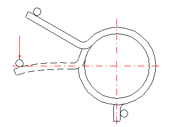
If the leg is supported freely (loaded) at one point, the leg only bends when the spring is loaded. This causes an increase in the actual functional angular deflection of the leg. The amount of bending in the leg increases with increased distance of the application point of the force from the coils of the spring (length of the leg). If both legs of the torsion spring are fixed, the working angle is given only by twisting the spring coils. Fixed mounting of the legs increases the accuracy of the calculation and improves the functions of the spring. Examples of fixing are shown on the following illustrations:
Select the method of loading that best meets the requirements of the entered
specifications.
Minimum permissible ratio between the permitted limit of bending stress of the chosen spring material and the actual working stress s8in the spring coils or the point of the leg bend. For a non-corrosive atmosphere and working temperature of an ambient environment of the spring exceeding 80 °C and with regards to the course and method of loading the torsion springs, it is advisable to use a level of safety in an interval of 1 .. 1.1. Springs working at higher temperatures or in an aggressive environment should be designed with a higher level of safety. Similarly with springs exposed to a load against the direction of coiling (see [1.8]) A higher level of safety should be considered in the spring design (by approx. 3-5%).
Choose the loading mode that best meets your entered data.
Two fields of fatigue stress on springs can be distinguished with springs exposed to fatigue loading. In the first field with a limited service life of the springs (lower than approx. 107 working cycles) the fatigue strength of the spring decreases with the increasing number of working cycles. In the field of unlimited service life (the desired service life of the spring is higher than 107 working cycles), the fatigue limit of the material and, thus, the strength of the spring remains approximately constant.
The level of safety gives the minimum permissible ratio between the fatigue bending strength of the spring and the actual maximum working stress s8in the spring coils or at the point of leg bend. For a non-corrosive atmosphere and working temperature in the immediate vicinity of the spring up to 80 °C and with regards to the course and mode of loading, it is advisable to choose a level of safety of springs in an interval of 1.05 .. 1.25. With determination of the level of safety, it is also necessary to consider the suitability of the chosen material for fatigue loading. With materials unsuitable for fatigue loading, it is advisable to increase the desired level of safety by up to 20 %. The springs working at higher temperatures or in a corrosive environment should be designed with higher levels of safety. In particular, corrosion significantly decreases the service life of a spring exposed to fatigue loading. Similarly with springs exposed to a load against the direction of coiling (see [1.8]) a higher level of safety in the spring design should be considered. Furthermore, when determining the level of safety, it is also necessary to consider the spring design [1.7]. With tight-coiled springs, friction appears between the coils during their functioning and this may cause the service life of the springs to shorten.
This paragraph can be used for selection of the spring material. Immediately after selection of the material from the list, all the information necessary for the design and calculation of the spring is displayed here. If you need more detailed information on the chosen material or you would like to define or modify its material, switch over to the "Material" sheet.
From the selection list choose the required processing of the spring. The cold winding shall be used for springs of ordinary sizes with a diameter of the wire up to 16 mm. Hot forming shall be used for the production of heavily loaded springs of greater sizes with a diameter of the over10 mm.
Choose the spring material from the list. In addition to five user materials, the list includes chosen materials of a single standard. If you wish to use materials of another standard, choose the respective standard in the "Material" sheet.
This paragraph includes information on the recommended use of the chosen material. The spring material should be designed with regards to the method of loading the spring and the operational conditions. If you must use a material less suitable, this fact should be reflected in the increased level of safety in the design of the spring (see row [1.19] or [1.23]) .
Properties of the chosen material, described in rows [2.4, 2.6] are evaluated in five degrees (excellent, very good, good, poor, insufficient), and the relative strength is described in row [2.5] in three degrees (high, medium, low).
All the parameters of the material that are necessary for calculation and are independent on the diameter of the used wire are displayed here.
This chapter includes the strength characteristics of the chosen material that are necessary for the design and calculation of the spring. The data characterizing strength of the material may be different for the same material, depending on the diameter of the used wire. Therefore, the values given here depend on the diameter of the wire. [4.9]
Maximum permissible stress of the spring material for infinite life and zero-to-maximum stress fluctuation.
This paragraph can be used for the design of the spring. The design of a torsion spring often has many various suitable solutions for the given input conditions. The application therefore proceeds iteratively with the spring design and, for the given input conditions, it passes through individual designs of the spring and a set of the most advantageous solutions is selected for the chosen qualitative standard. The chosen solutions are then offered in the form of a sorted table, from which you can choose a suitable design. The data on the chosen spring is then displayed immediately in the chapter of results.
The desired force arms of the spring are entered in this part. The first input column shows the desired length of the given force arm of the spring. The second column shows the permissible deviation from the desired value in the range of 0-99%. If the designed spring has to meet the desired value of the given parameter, zero deviation must be entered.
The working force arm is the distance of the force application point on the working leg from the spring axis. The arm of the supporting force means the distance of the fixed (support) point of the supporting leg from the spring axis. With regards to constructional feasibility of the spring, the entered dimensions of the force arms together with the chosen design of the legs [1.12, 1.15] also limit the diameter of the spring. Therefore, it is necessary to pay attention to avoid any discrepancy in the entered values of force arms or filters [3.15, 3.16]. If both legs of the spring are axial (type B), the lengths of the force arms must be the same (equal to the radius of the spring) and only the arm of the working force is entered.
This part can be used for entering the input data, describing the desired amount of load the spring has to withstand in the course of the working cycle. The first input column displays the desired value of the given load on the spring; the second column gives the permissible deviation from the desired value in the range of 0-99%. If the designed spring has to meet the desired value of the given loading, zero deviation must be entered.
In this part, you can enter the desired values of angular deflections of the working leg of the spring, which the spring has to reach under the working load specified in paragraph [3.4]. The first input column displays the desired value of the angular deflection of the spring; the second column gives the permissible deviation from the desired value in the range of 0-99%. If the designed spring has to precisely meet the desired value of the given parameter, zero deviation must be entered. The spring can be designed either for a known (desired) deflection of the working leg of a fully loaded spring or for the desired angle of the working stroke. The method of spring design that meets requirements of your entered data can be chosen by enabling of the respective check box at the beginning of row [3.8] or [3.9].
In this part, it is necessary to specify the various filters and extreme conditions of the design calculation. Their setting may significantly affect the course of the spring design and determine the speed, accuracy and quality of the design, the scope and number of suitable solutions and the qualitative standard for evaluation of the best designs.
If it is necessary to limit the outer diameter of the spring in its design (for example, if the spring is led through a sleeve), enable the check box at the beginning of the row and enter the maximum permissible value of the outer diameter of the spring into the input field.
If it is necessary to limit the inner diameter of the spring in its design (for example, if the spring is led on a pin), enable the check box at the beginning of the row and enter the minimum permissible value of the inner diameter of the spring into the input field.
If it is necessary to limit the length of the spring in its design, enable the check box at the beginning of the row and enter the maximum permissible value of the length of the part of the spring consisting of coils (see [4.14]).
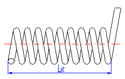
Active coils change their diameter with functional deformation (deflection of the leg). With setting a fine division, the design calculation tests a higher number of different designs of the spring and is able to give a more accurate and quality solution. On the other hand, this naturally causes a slower design calculation for the spring.
In the design of the spring, it is not possible to proceed without certain dimensional limitations. Some dimensions or ratios of individual dimensions of the spring are limited by the recommended values, specified by the respective standards and producers. This creates a file of extreme conditions, which must be taken into account with the spring design.
Strictly following these extreme conditions may cause elimination of some advantageous solutions from the resulting design, which may exceed some of the specified limits. However, despite this, they may be acceptable. Because of this, it is possible to set a filter of the design calculation in this row. This filter specifies the percentage of excess of the dimension limits of the spring. This brings more suitable solutions, but on the other hand, it is then necessary to visually check the chosen solution in the chapter of results and consider the acceptability of possibly exceeding the dimension limits of the springs. Exceeding of dimension limits is indicated by a change in color of the parameter value to red in the chapter of results.
With springs with B type supporting or working leg .. D (see [1.12, 1.15]) some stress concentrations appear in the point of the leg bend; these stress concentrations may be substantially higher than the calculated stress in the spring coils. The amount of these concentrations depends on the leg bending radius. As smaller bending radius, as higher values of stress peaks in the spring legs. If the designed spring has to meet requirements in the view of strength, the possible stress peaks in the spring legs must be lower than the permitted stress. This requirement must be taken into account when defining input data of the design calculation. One of the options is to enable this filter. The calculation then performs a preliminary check on the loading of the spring legs when designing the spring and the resulting design eliminates all solutions that do not meet the respective requirements.
The disadvantage of this approach can be seen in the fact that the design calculation can't design the optimal radius of the leg bends, which affect the amount of the possible stress peaks (within the defined input parameters, the calculation designs the bending radii of the legs as approximately double the wire diameter). This may lead to elimination of some advantageous solutions from the resulting design, where it would only be sufficient to increase the bending radius of the leg to meet the requirements of strength test. Sometimes it may be better (particularly for experienced users) to design the spring without this filter and then fine tune the strength test of the stress peaks in the point of the leg bend [4.44] manually setting the bending radii in row [4.18]. Another option is to design the torsion spring with this test disabled and with a sufficiently overdesigned level of safety [1.19, 1.23] to cover all the possible stress concentrations appearing in the spring legs.
If this filter of solutions is preset to "Yes", the resulting design eliminates all solutions where the calculated level of safety ss is lower than the desired level of safety given in row [1.19]. If the springs are exposed to a fatigue loading, this filter also eliminates the designs where the calculated level of safety sf is lower than the desired level of safety given in row [1.23].
If the filter is disabled, the resulting design includes all solutions where the calculated levels of safety are higher than or equal to 1. Due to the fact that the desired levels of safety are usually more or less well-founded estimations and only rarely reflect the exactly specified value whose excess could lead to the possible damage of the spring, it is better for experienced users to disable this filter when designing the spring and to evaluate the level of safety of the designed spring visually in the table of the design or in the chapter of results in rows [4.39], [4.44] or [4.49]).
In this row, the criteria for evaluation of the quality of individual suitable solutions of the spring design is given. The best solutions are then offered to the user in the table. The standard of quality can be chosen in the list according to the following description:
In some cases, it is good to execute the design successively for all criteria and compare the designs.
The design calculation of the spring works on the iteration principle. This row can be used for setting a number of iterations in the calculation and affecting the speed, accuracy and quality of the design. Generally, with more iterations comes slower calculations and a more accurate solution. However, it is advisable to also take into account other aspects when setting data in this row.
The speed of the design is affected by the capacity of the computer and the type of the design more than by the chosen number of iterations. Similarly, setting a high number of iterations may not always bring more accurate solutions for certain types of designs. Generally said, it is usually sufficient to set a low or medium number of iterations for common designs. Use of a high number of iterations is more important for very free designs where all or a majority of parameters of the working cycle in paragraphs [3.1, 3.4, 3.7] are entered with a considerable amount of permissible deviation and the desired diameter of the spring is not limited by filters in rows [3.12, 3.13, 3.14].
This part can be used to initiate the design calculation and then to chose a suitable spring from the table of designed solutions. With regards to the complexity of the spring design, it is not always possible to perform the design calculation automatically with a change in one of the input parameters, as with other calculations on the sheet. The design calculation is initiated once when pressing the button in row [3.23]. Information on the processing of the calculation is displayed in the dialogue.
After completion of the calculation, a table of designed solutions is filled up and assorted and the values of the best (chosen) solution are transferred automatically into the chapter of results. The table is assorted according to the criterion set in row [3.22]. The table of designed solutions can be re-assorted whenever using another sorting criterion.
If the design calculation was unsuccessful and no sufficient solution was found, this fact is indicated as a warning message and the table of solutions remains in its original state. The following text shows some particular problems that may appear along with their possible remedies:
Meaning of parameters in the table:
| D | Mean spring diameter |
| De | Outer spring diameter |
| Di | Inner spring diameter |
| d | Wire diameter |
| n | Number of active coils |
| d0 | The angle between the legs in free state |
| a1 | Angular deflection of the working leg with a preloaded spring |
| a8 | Angular deflection of the working leg with a fully loaded spring |
| Rf | Working force arm |
| M1 | Minimum working load |
| M8 | Maximum working load |
| s8 | Stress of the fully loaded spring |
| ss | Level of safety of a spring exposed to static loading |
| sf | Level of safety of a spring exposed to a fatigue loading |
| m | Weight of the spring |
| quality | A comparative value showing the quality of the solution with regards to the chosen qualitative standard [3.22]. The lower the given value, the better the quality of the design. |
All the necessary parameters describing the designed spring for the given load and the dimensions of the spring are calculated in this paragraph. Entry data is transferred into the calculation from the table of solutions [3.24] of the chosen design of the spring, or from some of the supplementary calculations [7,8,9]. For easier evaluation and value checks of individual parameters of the spring, some data is completed with their recommended limit values (shown in the green fields in the listing). Excess of the recommended values is indicated by a change in color of the parameter to red. The critical values that might cause non-functionality or damage to the spring are indicated by a change in color of the whole field to red.
The parameters of the spring are divided in the listing into paragraphs according to the status of the spring; the strength test of the spring is given at the end of the chapter. The meanings of individual dimensional parameters of the spring can be seen in the illustration.
If there is a need to tune some parameters of the designed spring (e.g. a rounding of the designed dimensions), use some of the supplementary calculations. [7,8,9]
Pressing the button in this row refreshes the values in the listing of parameters of the spring with the data from the design of the spring chosen in the table of solutions [3.24].
This parameter gives the ratio of D/d between the mean diameter of the spring and the diameter of the used wire.
The length of the spring is specified by the given number of coils and the spring pitch. In the case of tight-coiled springs, the length calculated here is a theoretical length only. Due to imperfectly abutting coils and production tolerances of the used wire diameter, the actual length of the spring making up the coils is usually greater by approximately 3-5%.
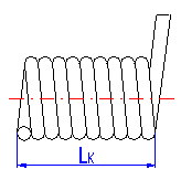

With regards to the constructional feasibility of the designed spring, it is necessary to enter the length of the supporting or working leg to keep in mind that the chosen length of the leg should be sufficient with regards to the desired length of the arm of the supporting or working force given in row [4.3]. Non-conformity with this condition is indicated by a change in color of the input field to red. On springs with type B legs .. D (see [1.12, 1.15]), it is further recommended to specify the minimum length of the leg as triple the bending radius on the leg.

On springs with a type B supporting or working leg .. D (see [1.12, 1.15]), some stress concentrations appear in the points of the leg bend; these stress concentrations may be substantially higher than the calculated stress in the spring coils. The amount of these concentrations depends on the leg bending radius. The smaller the bending radius, the higher the values of stress peaks in the spring legs. If the designed spring must meet the requirements in the view of strength, the possible stress peaks in the spring legs must be lower than the permitted stress. Therefore, it is necessary to test the designed spring in part [4.44] after entering the bending radius.
The angular deflection (bending angle) a of the working leg depends, theoretically, on the moment stiffness of the spring and is given by the twisting of the spring coils caused by the working force. In fact, this is applicable only with springs with fixed legs (see [1.13]).
In the case of springs with one or both freely supported legs, the working force causes additional bending to the leg. The actual (corrected) angular deflection aC is then greater by the angle given by the leg bending when compared with the theoretical value. The amount of bending in the leg increases with increasing distance of the point of action of the working force from the spring coils (length of the leg).
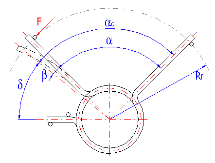
Active coils change their diameter with the functional deformation (deflection of the leg) of a torsion spring. In the case of springs loaded in the direction of the coiling (see [1.8]), the diameter decreases, and with springs loaded against the direction of coiling, the diameter increases. If the spring is led on a pin or in a sleeve, it is important to know the maximum outer or minimum inner diameter of the fully loaded spring.
In the case of a tight-coiled spring loaded in the direction of coiling (see [1.7, 1.8]), its length increases with the loading of the spring. The maximum length is then reached with the fully loaded spring. The length given here is a theoretical value only. Due to imperfectly abutting coils and production tolerances of the used wire diameter, the actual length of the spring making up the coils is usually greater by approx. 3-5 %.
The strength test of a torsion spring is performed by comparison of the maximum permissible bending stress of the chosen material [4.42] with a corrected stress on the spring in fully loaded condition [4.41]. If the designed spring has to meet the strength test to the full extent, the resulting level of safety [4.43] must be higher or equal to the desired level of safety [1.19].
The stress appearing in the spring coil at the given load is calculated for a simple bend for the central ray of the coil. Above all, due to the coil radius, the actual stress in the extreme fibres of the coils is substantially higher. Therefore, the stress is corrected in the calculation using a correction coefficient (see row [1.5]).
In the case of springs with a type B supporting or working leg .. D (see [1.12, 1.15]), some stress concentrations appear at the point of the leg bend; these stress concentrations may be substantially higher than the calculated stress in the spring coils. The amount of these concentrations depends on the leg bending radius [4.18]. The smaller the bending radius, the higher the values of stress peaks in the spring legs. The strength test of a compression spring is then performed by comparison of the permissible bending stress limit of the chosen material [4.47] with maximum stress at the point of the bend on the leg of the fully loaded spring [4.46]. If the designed spring must meet the strength test to the full extent, the resulting level of safety [4.48] must be higher or equal to the desired level of safety [1.19]. If some stress concentrations appear in both legs of the spring, the test is performed on the leg under the worst stress conditions.
The strength test of a torsion spring exposed to a fatigue loading is performed by comparison of the maximum fatigue strength of the material specified for the given course of loading [4.52] with corrected stress in the coils or at the point of the bend of the fully loaded spring leg [4.50, 4.51]. If the designed spring must meet the strength test to the full extent, the resulting level of safety [4.53] must be higher or equal to the desired level of safety [1.23]. Even in the case of a spring exposed to a fatigue loading, conditions of a static strength test must naturally be met [4.39, 4.44].
Determination of the maximum fatigue strength of the spring is based on the ultimate fatigue strength of the chosen material and the given course of loading of the spring using a Goodman's fatigue diagram.
This paragraph can be used for calculations of the parameters of a spring (designed in paragraph [4]), which is exposed to a specific operational load. The paragraph [5.1] is designed for the calculation of the angular deflection aX of the spring working leg, loaded by the given working force Fx. Paragraph [5.6] enables you to find the working force or the moment, needed for twisting the spring working leg to the given angular deflection aX.
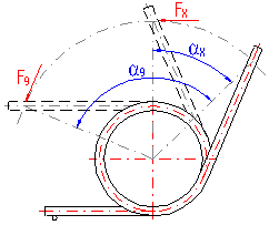
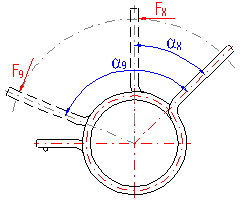
This paragraph gives the parameters of a strength test of a spring exposed to a fatigue loading. The strength test of a spring exposed to a fatigue loading is performed in comparison to the maximum fatigue strength of the used material specified for the given course of loading [6.8] with a corrected stress on the spring coils or at the point of the bend on the leg in a fully loaded condition [6.3]. If the designed spring must meet the strength test to the full extent, the resulting level of safety [6.9] must be higher or equal to the desired level of safety [1.23].
For the purposes of a strength test of a spring exposed to a fatigue loading, the stress of the spring is corrected using the higher of the corrective coefficients in rows [4.40, 4.45].
Maximum permissible stress of the spring material for infinite life and zero-to-maximum stress fluctuation.
Determination of the maximum fatigue strength of the spring is based on the ultimate fatigue strength of the chosen material and the given course of loading of the spring using a Goodman's fatigue diagram.
The first of the supplementary calculations can be found in this paragraph. This calculation includes three functions.
The calculation located in this paragraph includes two functions.
The calculation located in this paragraph includes two functions.
Information on options of 2D and 3D graphic outputs and information on cooperation with 2D and 3D CAD systems can be found in the document "Graphic output, CAD systems".
Information on setting of calculation parameters and setting of the language can be found in the document "Setting calculations, change the language".
When designing a spring, it is not possible to proceed without certain dimensional limitations. Some dimensions or ratios of the individual dimensions of the spring are limited by the recommended values determined by the respective standards (see e.g. DIN 2088), as well as by various producers. This creates a file of extreme conditions that must be taken into account in the design of the spring.
Therefore, different recommended dimension limits may be used for the spring, which can be modified in this paragraph according to the user's requirements. The minimum values of the individual parameters can be entered in the first column, and the maximum values in the second column. In the case of setting freer extreme conditions (by decreasing the minimum or increasing the maximum values), the application selects a suitable solution from a wider range of suitable solutions. This increases the chances to find a higher quality solution. On the other hand, this creates a risk that the chosen supplier will not be able to produce the designed spring.
If there are not any special requirements for the dimension limits of the spring, the predefined setting can be used. Pressing the button in row [3.7] sets the implicit values corresponding to the file of extreme conditions in the input fields for commonly delivered springs.
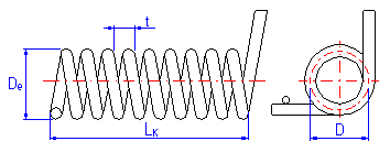
This parameter gives the ratio of D/d between the mean diameter of the spring and the diameter of the used wire. According to DIN 2088, the permissible ratio of coiling is in the interval of 4 to 20.
According to DIN 2088, it is max. 360 mm.
Not prescribed by the standard, but usually LK<10*D with commonly produced springs .
According to DIN 2088, max. 630 mm.
Not prescribed by the standard, but with commonly produced loose-coiled springs, it is usually 0.3*D < t < 0.5*D.
The DIN 2088 standard prescribes a minimum two active coils for torsion springs.
General information on how to modify and extend calculation workbooks is mentioned in the document "Workbook (calculation) modifications".
With the calculation of springs, it is not possible to intervene in the design calculation of the spring using modifications and changes in the workbook. With regards to the complexity of the task to design a spring, this calculation is implemented as an internal function of the workbook.
^