The calculation is to be used for geometrical and strength design of metal springs of various types and designs, subjected to static or cyclic loads. The program performs the following tasks:
Geometrical design and calculation of working cycle parameters for metal springs of the following types and designs:
Automatic proposal (finding) of a spring with suitable dimensions.
Static and dynamic strength check.
The application includes a table of commonly used spring materials according to EN, ASTM/SAE, DIN, BS, JIS, UNI, SIS, CSN and others.
The calculation is based on data, procedures, algorithms and data from specialized literature and standards EN 13906, DIN 2088, DIN 2089, DIN 2090, DIN 2091, DIN 2092, DIN 2093, DIN 2095, DIN 2096, DIN 2097.
User interface.
Download.
Purchase, Price list.
Information on the syntax and control of the calculation can be found in the document "Control, structure and syntax of calculations".
Information on the purpose, use and control of the paragraph "Information on the project" can be found in the document "Information on the project".
Springs are constructional elements designed to retain and accumulate mechanical energy, working on the principle of flexible deformation of material. Springs belong to the most loaded machine components and are usually used as:
Spring function is evaluated according to the course and extent of its deformation depending on its load.
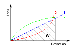
Based on the deformation pattern, springs can be divided into the following three types:
The W area under the spring characteristic curve represents the deformation work (energy) of a spring performed by the spring during its loading. Deformation energy of springs subjected to compression, tension or bending is specified by the formula:

for springs subjected to torsion:

The basic quantity specifying the spring functionality is its stiffness (spring constant). Spring constant k specifies the intensity of load (force or torque) which causes unit deformation (shift or turning) of the spring.
![]()
![]()
The spring with linear characteristics have invariable spring constant; other springs have variable spring constant.
Springs are mounted with initial stress, i.e. in the state when the spring is subjected to the minimum working load. In view of spring function, there are four basic states of springs:
| State of the spring | Description of states of a spring | index |
| free | the spring is not loaded | 0 |
| preloaded | the spring is exposed to minimum operational loading | 1 |
| fully loaded | the spring is exposed to maximum operational loading | 8 |
| limiting | the spring is exposed to the limit load – given by the material strength or design limitations (e.g. compression of the coil spring to bring all coils into contact). | 9 |
The above-mentioned indexes are used in the calculation to specify individual parameters of the spring related to the given state of the spring.
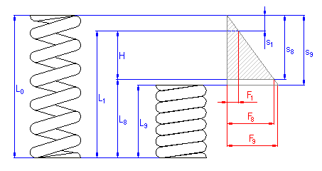
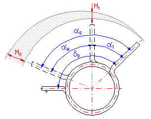
The difference between the spring deformations in full load condition and initial stress condition is called the spring working stroke H, aH.
As regards the strength check and the service life, there are the following two types of metal spring loads:
Metal springs can be divided into groups according to many aspects. Division according to load type and structural design of a spring can be considered as basic. The most common spring types are described in detail as follows:
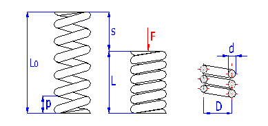
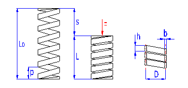
Springs of cylindrical shape made of helically coiled wires, with constant clearance between the active coils, able to absorb external counter-acting forces applied against each other in their axis. Springs with wire diameter up to approx. 16 mm are usually cold wound. Hot forming shall be used for the production of heavily loaded springs of greater sizes with a diameter of the over 10 mm. Compression springs are usually made of wires and rods of round section. Springs of rectangular wire are most often used in applications where low constructional height of the spring (springs with b>h) is required together with relatively high load.
|
Springs of round wire |
Springs of rectangular wire |
|
|
|
 |
 |
 |
 |
|
|
|
where:
c ... spring index (c=D/d; c=D/b) [-]
b ... wire width [mm, in]
d ... wire diameter [mm, in]
D ... mean spring diameter [mm, in]
F ... loading of spring [N, lb]
G ... modulus of elasticity in shear [MPa, psi]
h ... wire height [mm, in]
k ... spring constant [N/mm, lb/in]
Ks ... curvature correction factor [-]
L0 ... free spring length [mm, in]
LS ... solid length [mm, in]
n ... number of active coils [-]
p ... pitch between coils [mm, in]
s ... spring deflection [mm, in]
e,y ... shape coefficient [-] (e.g. DIN 2090)
t ... torsional stress of the spring
material [MPa,
psi]
Curvature correction factor
The coil bending causes additional bending stresses in coil springs.
Therefore the calculation uses the correction coefficient to correct the
tension.
For springs of round section wire, the correction coefficient is determined with
the given spring coiling ratio by several empirically defined formulas (Wahl,
Bergsträsserr, Göhner, ...). This calculation uses the following relation:

For springs of rectangular section wire, the correction coefficient is
determined for the given spring index and b/h ratio from appropriate nomograms.
In this calculation the correction coefficient is already included in the shape
coefficient
y.
| cold formed | hot formed | |
| spring index c | 4 - 16 | 3 - 12 |
| outer diameter De | max. 350 mm | max. 460 mm |
| number of active coils n | min. 2 | min. 3 |
| ratio b/h | 1:5 - 5:1 | |
| free length L0 | max. 1000 mm | |
| slenderness ratio L0/D | 1 - 10 | |
| pitch p | (0.3 - 0.6) D; min. 1.5 d | |
In case of compression springs, several various designs of spring ends are used. These differ in numbers of ends and machined coils and designs of supporting surfaces of the springs.
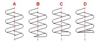
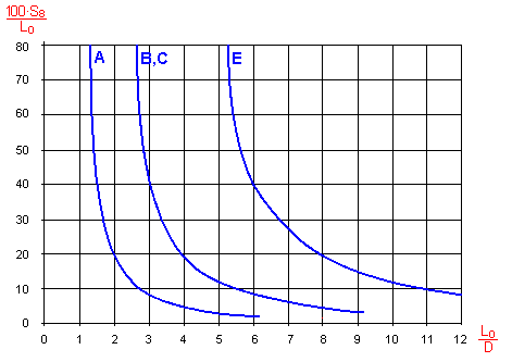
In case of compression springs, it is always necessary to check its protection against side deflection. The check is performed by comparison of the maximum working deformation of the spring with the permitted deformation. The value of the permitted deformation is determined empirically for the given slenderness ratio of the spring L0/D and the type of seating of the spring. Generally, the risk of possible side deflection increases with an increasing value of the slenderness ratio and increasing value of the working compression of the spring. The manner of seating of the spring has a significant effect on its possible side deflection.
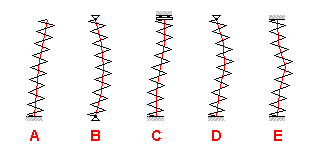
A spring which cannot be designed as secured against side deflection is usually installed on a pin or inside a sleeve. If there is a danger of damage of the spring due to friction, the spring can be divided into several shorter springs arranged in series.
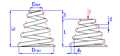
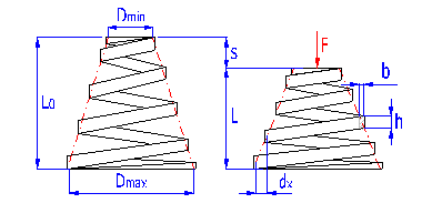
Springs of conical shape made of helically coiled wires, with constant clearance between the active coils, able to absorb external counter-acting forces applied against each other in their axis. Springs with wire diameter up to approx. 16 mm are usually cold wound. Hot forming shall be used for the production of heavily loaded springs of greater sizes with a diameter of the over 10 mm. Conical springs are usually used if the spring constant is to rise together with its progressing compression.
With increasing compression of the conical spring, its active coils are brought into contact with adjacent coils gradually (first the coils with the largest diameter). These coils then do not participate in further compression of the spring which results in gradual increase in the spring constant. Working characteristics can therefore be divided into two areas:
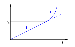
The limit force FC depends on the pitch between the coils p, i.e. also on the selected size of free spring length L0. The limit force FC increases together with increasing spring length and the working area with linear spring constant rises.
|
Springs of round wire |
Springs of rectangular wire |
 |
 |
|
I. Working area with linear characteristics F≤FC |
|
|
|
|
 |
 |
 |
 |
 |
 |
|
|
|
|
II. Working area with progressive characteristics F>FC |
|
 |
 |
 |
 |
 |
 |
 |
 |
 |
 |
 |
|
where:
cmin ... min. spring index (cmin=Dmin/d; cmin=Dmin/b) [-]
cmax ... max. spring index (cmax=Dmax/d; cmax=Dmax/b) [-]
b ... wire width [mm, in]
d ... wire diameter [mm, in]
dx .. shift of coils [mm, in]
Dmin .. min. mean spring diameter [mm, in]
Dmax .. max. mean spring diameter [mm, in]
F ... loading of spring [N, lb]
G ... modulus of elasticity in shear [MPa, psi]
h ... wire height [mm, in]
k ... spring rate [N/mm, lb/in]
Ks ... curvature correction factor [-]
L0 ... free spring length [mm, in]
LS ... solid length [mm, in]
n ... number of active coils [-]
p ... pitch between coils [mm, in]
s ... spring deflection [mm, in]
e,y ... shape coefficient [-] (e.g. DIN 2090)
t ... torsional stress of the spring
material [MPa,
psi]
Curvature correction factor
The coil bending causes additional bending stresses in coil springs.
Therefore the calculation uses the correction coefficient to correct the
tension.
For springs of round section wire, the correction coefficient is determined with
the given spring coiling ratio by several empirically defined formulas (Wahl,
Bergsträsserr, Göhner, ...). This calculation uses the following relation:

For springs of rectangular section wire, the correction coefficient is
determined for the given spring index and b/h ratio from appropriate nomograms.
In this calculation the correction coefficient is already included in the shape
coefficient
y.
| spring index cmin | min. 3 |
| spring index cmax | max. 20 |
| diameter Dmax | max. 350 mm |
| ratio Dmax/Dmin | min. 2 |
| number of active coils n | min. 2 |
| ratio b/h | 1:5 - 5:1 |
| slenderness ratio L0/D | 1 - 5 |
| pitch p | (0.4 - 0.7) D; min. 1.5 d |
In case of compression springs, several various designs of spring ends are used. These differ in numbers of ends and machined coils and designs of supporting surfaces of the springs.
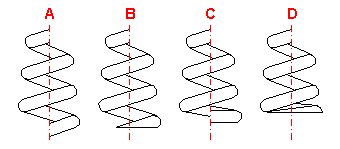
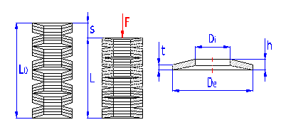
Annular rings of hollow truncated cone, able to absorb external axial forces counter-acting against each other. The spring section is usually rectangular. Springs of larger sizes (t > 6 mm) are sometimes made with machined contact flats.
Belleville springs are designed for higher loads with low deformations. They are used individually or in sets. When using springs in a set it is necessary to take account of friction effects. Friction in the set accounts for 3 – 5% of loading per each layer. Working load must then be increased by this force.
Stress occurring in the Belleville spring is rather complex. Maximum stress (compressive) develops in the inner top edge. Tensile stress occurs on the bottom outer edge. Maximum compressive stress serves for strength check of springs subjected to static load. In the springs subjected to cyclic (fatigue) load the pattern of tensile stresses is checked.
Working characteristics
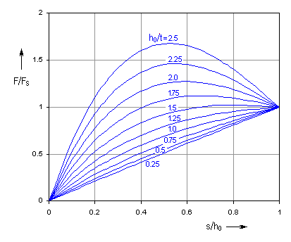
The shape of the Belleville spring characteristic curve is strongly affected by the relative height h0/t. For small values of the relative height the spring has nearly linear working characteristics; with rising ratio the characteristics are sharply degressive.
Design of a set
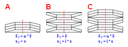
In the case of the Belleville springs there are three kinds of springs arrangement in the set.
| Single spring |
|
|
|
|
|
|
 |
 |
|
|
 |
 |
 |
 |
| Springs set |
 |
where:
De .. outside diameter [mm, in]
Di .. inside diameter [mm, in]
E ... modulus of elasticity in tension [MPa, psi]
F ... spring force [N, lb]
FS ... force of fully compressed spring [mm, in]
FT ... total force of set [mm, in]
h ... disc height [mm, in]
h0 ... inside height of disc (h0=h-t) [mm, in]
i ... no. of sets (disc) in series in a stack [-]
k ... spring rate [N/mm, lb/in]
kT ... total stiffness of set [N/mm, lb/in]
K1, K2, K3 .. shape coefficient [-]
L0 ... free spring length [mm, in]
LS ... solid length [mm, in]
n ... no. of parallel discs in a set [-]
s ... spring deflection [mm, in]
sT ... total deflection o set [mm, in]
t ... material thickness [mm, in]
d ... diameter ratio (d=De/Di) [-]
m ... Poisson's ratio [-]
sOM,
sI,
sII,
sIII,
sIV ... material stress in the
given point of the spring [MPa,
psi]
| diameter ratio De/Di | 1.75 - 2.5 |
| relative height h0/t | 0.4 - 1.4 |
| ratio De/t | 16 - 40 |
| no. of parallel discs n | max. 3 |
| no. of sets (disc) in series i | max. 20 |
| total number of disc n*i | max. 30 |
| slenderness ratio L0/De | max. 3 |
Friction has a significant effect on the function of the Belleville spring. Loading of the spring develops friction on the contact surface (edges) of the spring. In the case of parallel arrangement of the springs there is also surface friction between the discs. The effects of friction result in an increase of force during the loading and decrease of force during relieving of the spring.
| single spring | ± 2...3 % |
| 2 parallel arranged springs | ± 4...6 % |
| 3 parallel arranged springs | ± 6...9 % |
| 4 parallel arranged springs | ± 8...12 % |
| 5 parallel arranged springs | ± 10...15 % |
The amount of friction depends on many factors (spring design, material, surface treatment, number of springs in the set, lubricant type, etc.). Its impact on the spring loading cannot be theoretically exactly determined. The following formula is used to determine the approximate corrected force of the spring:

where:
mM .. coefficient of surface friction [-]
mR .. coefficient of edge
friction[-]
- .... on loading
+ ... on unloading
| Spring type | mM | mR |
| standard | 0.003 - 0.030 | 0.02 - 0.05 |
| with machined contact flats | 0.002 - 0.015 | 0.01 - 0.03 |

Springs of larger sizes (t > 6 mm) are sometimes made with machined contact flats. Formulas for the calculation of these springs are slightly different and they can be found e.g. in DIN 2092.
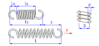
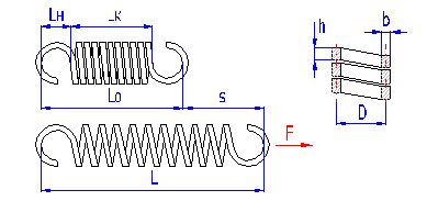
Springs of cylindrical shape made of helically coiled wires, with constant clearance between the active coils, able to absorb external axial forces counter-acting from each other. Springs with wire diameter up to approx. 16 mm are usually cold wound. Hot forming shall be used for the production of heavily loaded springs of greater sizes with a diameter of the over 10 mm. Tension springs are usually made of wires and rods of round section. Springs made of rectangular wire are used very rarely.
With regards to the considerable effects of the shape and design of fixing eyes on reduction of the spring's service life and impossibility of perfect shot peening of the spring, it is not advisable to use tension springs exposed to fatigue loading. If it is necessary to use a tension spring with fatigue loading, it is advisable to avoid use of fixing eyes and choose another type of fixing of the spring.
Spring design
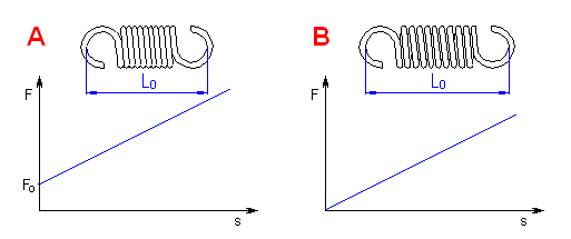
Tension springs are used in two basic designs:
|
Springs of round wire |
Springs of rectangular wire |
 |
 |
|
|
|
| A. Spring with prestressing | |
 |
|
 |
|
| B. Spring without inner prestressing | |
|
|
|
 |
 |
where:
c ... spring index (c=D/d; c=D/b) [-]
b ... wire width [mm, in]
d ... wire diameter [mm, in]
D ... mean spring diameter [mm, in]
F ... loading of spring [N, lb]
F0 ... initial tension [N, lb]
G ... modulus of elasticity in shear [MPa, psi]
h ... wire height [mm, in]
k ... spring constant [N/mm, lb/in]
Ks ... curvature correction factor [-]
L0 ... free spring length [mm, in]
LH ... height of spring hook [mm, in]
LK ... length of active spring section [mm, in]
n ... number of active coils [-]
p ... pitch between coils [mm, in]
s ... spring deflection [mm, in]
e,y ... shape coefficient [-] (e.g. DIN 2090)
t ... torsional stress of the spring
material [MPa,
psi]
t0 ... initial stress [MPa,
psi]
Curvature correction factor
The coil bending causes additional bending stresses in coil springs.
Therefore the calculation uses the correction coefficient to correct the
tension.
For springs of round section wire, the correction coefficient is determined with
the given spring coiling ratio by several empirically defined formulas (Wahl,
Bergsträsserr, Göhner, ...). This calculation uses the following relation:

For springs of rectangular section wire, the correction coefficient is
determined for the given spring index and b/h ratio from appropriate nomograms.
In this calculation the correction coefficient is already included in the shape
coefficient
y.
Spring initial stress
Initial stress arises in the spring coils during winding of the spring and its
magnitude is dependent on the spring material, spring index and the way of
winding. The usual values of the initial stress are within the range:

Higher values are technically difficult to achieve, the lower values are very difficult to measure with sufficient accuracy. To determine the spring initial stress for springs wound on a winding bench, the DIN 2089 standard specifies the following formula:
![]()
Initial tension is given by the formula:

| spring index c | 4 - 16 |
| outer diameter De | max. 350 mm |
| number of active coils n | min. 3 |
| ratio b/h | 1:5 - 5:1 |
| free length L0 | max. 1500 mm |
| slenderness ratio L0/D | 1 - 15 |
| pitch p | (0.2 - 0.4) D - for spring without prestressing |
Tension springs are used in many different designs. The most common spring ends can be found in the following picture. The type of design of the spring ends depends on the desired method of fixing the spring, its dimensions and the amount of loading.
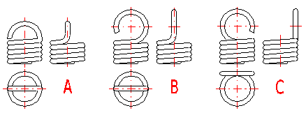
A ... Half loop
B ... Full loop
C ... Full loop on side
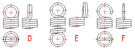
D ... Double twisted full loop
E ... Double twisted full loop on side
F ... Inside full loop
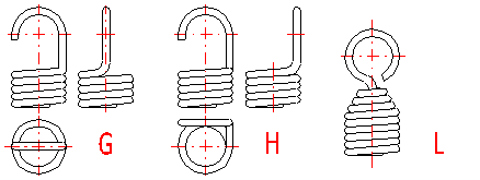
G ... Raised hook
H ... Raised hook on side
L ... Coned end with swivel eye
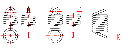
I ... Small eye
J ... Small eye on side
K ... Inclined full loop
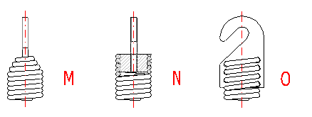
M ... Coned end with swivel bolt
N ... Screwed
O ... Screwed in shackle
Tension springs are usually fixed using fixing eyes of several types (A .. J) with different heights of the eyes and differing properties. Fixing eyes are the best solution in the technological aspect, however, this brings certain problems in view of loading capacity of the spring. Loading of the spring creates a concentration of stress on the fixing eyes and this may be substantially higher than the calculated stress in the spring coils. In view of bending stress appearing in the fixing eye, small eyes (type I, J) or double eyes (type D, E) are the best solution. In view of concentration of stress in torsion at the point of transition of the coil into the loop, the full loops on the side (type C,E,I) are the best solution. For individual designs of fixing eyes, the following values of eye height are prescribed:
| Design | A | B, C | D, E | F | G, H | I, J | K |
| Eye height | {0.55..0.8} Di | {0.8..1.1} Di | ~ Di | {1.05..1.2} Di | > 1.2 Di | < 0.6 Di | {0.35..0.9} Di |
Hot formed springs, rectangular wire springs and cyclically loaded springs are
usually used without spring hooks (M..O. design). With designs without fixing
eyes the spring is fixed using end coils whose pitch does not change during
functional deformation of the spring.
Loading of the spring creates a concentration of stress in the fixing eyes and this may be substantially higher than the calculated stress in the spring coils. It is therefore recommended to check such springs also in view of loading of the fixing eyes.
The amounts of possible concentrations depend on the type, design and dimensions of the eye and it is very difficult to calculate them theoretically. Despite this, at least approximate calculations are used to provide some orientation information on any possible exceeding of strength limits of the chosen material of the spring. Two basic strength checks are performed with regards to the design of the fixing eye:

Check of bending stress in spring hook
The amount of the bending stress which appears in the bend of the eye depends on the radius of the spring hook rb. The amount of stress increases with an increasing radius and vice versa. The following formula can be used to determine bending stress:

Check of stress in transition bend
In the case of tension springs, the highest stress concentrations appear in points of transitions of coils to spring hook. The size of these stresses depends on the transition bend radius rs. Generally speaking, the size of stress in the transition bend decreases with an increasing radius of the bend and vice versa. The following formula can be used to determine peak stress:

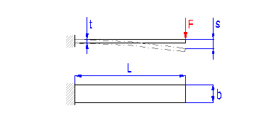
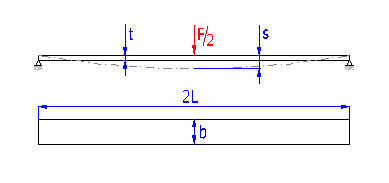
Springs based on the principle of long slander beams of rectangular section subjected to bending. They are used as cantilever springs (fixed at one end), or as simple beams (fixed at both ends). The leaf springs can be used either independently or in sets (laminated leaf springs).
Single springs
Laminated leaf springs
Spring design
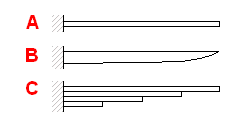
Leaf springs are used in many different designs and shapes. They can be
divided into three groups for calculation purposes:
|
A. Single springs with constant profile |
||
|
|
|
|
 |
 |
 |
 |
||
 |
||
|
B. Single springs with parabolic profile |
|
|
|
|
 |
 |
|
|
|
 |
|
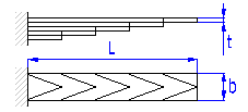
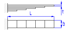
| C. Laminated leaf springs | |
 |
 |
 |
|
 |
|
 |
 |
where:
b ... width of spring leaf [mm, in]
b' ... leaf width at end of spring [mm, in]
E ... modulus of elasticity in tension [MPa, psi]
F ... loading of spring [N, lb]
k ... spring constant [N/mm, lb/in]
L ... functional spring length [mm, in]
L' ... length of leaf with constant thickness [mm, in]
n ... total number of spring leaf [-]
n' ... number of extra full-length leaves [-]
s ... spring deflection [mm, in]
t ... thickness of spring leaf [mm, in]
t' ... leaf thickness at end of spring [mm, in]
y ... shape coefficient [-]
s ... bending stress of the spring material [MPa,
psi]
Extra leaves
Spring leaves of full length, rectangular shape with constant profile. These
leaves are added to the spring for two reasons:

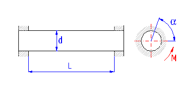
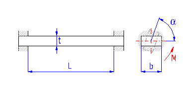
Springs based on the principle of long slender bars of circular or rectangular section subjected to torsion. The ends of bars with circular section are mostly fixed by means of grooving. Sometimes one end is square-shaped in order to facilitate attachment. Torsion bar springs must be secured against bending stress.
|
Bar with round section |
Bar with rectangular section |
|
|
|
 |
 |
 |
 |
|
|
|
where:
b ... bar width [mm, in]
d ... bar diameter [mm, in]
M ... loading of spring [Nmm, lb in]
G ... modulus of elasticity in shear [MPa, psi]
k ... torque spring rate [Nmm/°, lb in/°]
L ... functional spring length [mm, in]
t ... bar thickness [mm, in]
a ... angular deflection [°]
b,g ... shape coefficient [-]
t ... torsional stress of the spring material [MPa,
psi]
Shape coefficients
These coefficients take stress distribution in the bar section b/t
into consideration. Their value can be found in the table:
| b/t | 1 | 1.2 | 1.5 | 2 | 3 | 4 | 5 | 6 | 8 | 10 | ∞ |
| b | 0.1406 | 0.166 | 0.196 | 0.229 | 0.263 | 0.281 | 0.291 | 0.299 | 0.307 | 0.312 | 0.333 |
| g | 0.208 | 0.219 | 0.231 | 0.246 | 0.267 | 0.282 | 0.291 | 0.299 | 0.307 | 0.312 | 0.333 |
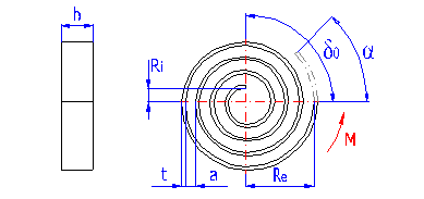
The spring made of a strip with rectangular section wound into the shape of Archimedes spiral, with constant spacing between its active coils, loaded with torque in the direction of the winding.
|
|
|
|
 |
 |
|
|
where:
a ... space between coils [mm, in]
b ... width of spring strip [mm, in]
M ... loading of spring [Nmm, lb in]
E ... modulus of elasticity in tension [MPa, psi]
k ... torque spring rate [Nmm/°, lb in/°]
Kb ... curvature correction factor [-]
L ... functional spring length [mm, in]
n ... number of active coils [-]
t ... thickness of spring strip [mm, in]
Re ... outer radius [mm, in]
Ri ... inner radius [mm, in]
a ... angular deflection [°]
d0 ... leg angle of free spring [°]
s ... bending stress of the spring material [MPa,
psi]
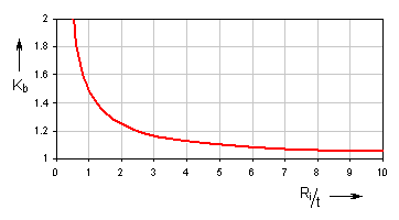
Curvature correction factor
Correction coefficient represents the spring additional stress resulting
from its curvature. Its value can be found in the graph:
| ratio Ri/t | min. 3 |
| ratio b/t | 1 - 15 |
| number of active coils n0 | min. 2 |
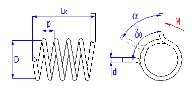
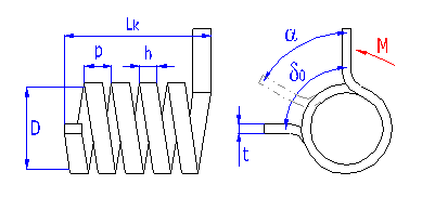
Springs of cylindrical shape made of helically coiled wires, with constant spacing between the active coils, able to absorb external forces applied in the planes perpendicular to the winding axis through a torque in the direction of winding or unwinding. Springs with wire diameter up to approx. 16 mm are usually cold wound. Hot forming shall be used for the production of heavily loaded springs of greater sizes with a diameter of the over 10 mm.
Spring design
Torsion springs are produced in two basic designs: tight-coiled and loose-coiled (with clearance between the coils). If the springs are exposed to a static loading, the tight-coiled springs are recommended. However, if friction appears between the coils of these springs while they are working, this may cause the service life of the springs to decrease. In addition to this, the close distance of the coils prevents perfect shot peening of the spring. Therefore loose-coiled springs are suitable for use with fatigue loading. The pitch of the spring is usually in the range of 0.3*D < p < 0.5*D.
|
Springs of round wire |
Springs of rectangular wire |
|
|
|
 |
 |
 |
 |
|
|
|
where:
c ... spring index (c=D/d; c=D/t) [-]
b ... wire width [mm, in]
d ... wire diameter [mm, in]
D ... mean spring diameter [mm, in]
M ... loading of spring [Nmm, lb in]
E ... modulus of elasticity in tension [MPa, psi]
k ... torque spring rate [Nmm/°, lb in/°]
Kb ... curvature correction factor [-]
LK ... Length of coiled section [mm, in]
n ... number of active coils [-]
p ... pitch between coils [mm, in]
t ... wire thickness [mm, in]
a ... angular deflection [°]
d0 ... leg angle of free spring
[°]
s ... bending stress of the spring material [MPa,
psi]
Curvature correction factor
Correction coefficient represents the spring additional stress resulting
from its curvature.
Functional dimensions of the spring
Functional deformation (shift of the arm) of the torsional spring leads to the
change of its dimensions. The diameter of springs loaded in the direction of
coil winding decreases during its loading:

In addition, the length of close wound spring grows:

| spring index c | 4 - 16 |
| outer diameter De | max. 350 mm |
| number of active coils n | min. 2 |
| ratio b/t | 1 - 10 |
| length of coiled section LK | max. 800 mm |
| slenderness ratio LK/D | 1 - 10 |
With regards to the possible occurrence of stress concentrations, the shape of the legs of the torsion spring should be as simple as possible. The basic types of legs used with torsion springs are given in the illustration. The option of the leg design depends on the desired method of setting the spring, its dimensions and desired distance of the loading application point from the spring axis, while the supporting and working legs of the spring may be different.
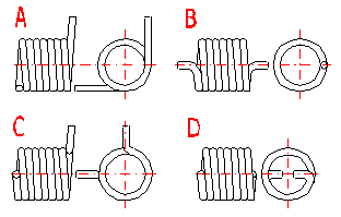
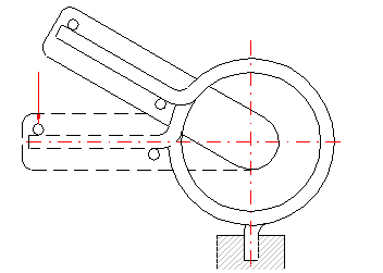
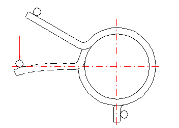
If both legs of the torsion spring are fixed, the working angle is given only by twisting the spring coils. If the leg is supported freely (loaded) at one point, the leg only bends when the spring is loaded. This causes an increase in the actual functional angular deflection of the leg. The amount of bending in the leg increases with increased distance of the application point of the force from the coils of the spring (length of the leg). Fixed mounting of the legs increases the accuracy of the calculation and improves the functions of the spring.
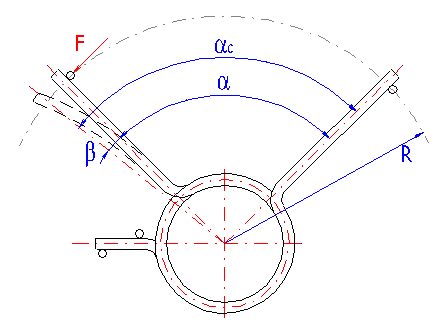
Actual (adjusted) angular deflection of the spring with a free leaning arm
will then be for:
- radial arms

- tangential arms


The springs with bended arms are subjected to concentrations of tension at the bends which can be much higher than the calculated stress in the spring coils. The amount of these concentrations depends on the leg bending radius. The smaller the bending radius, the higher the values of stress peaks in the spring legs. The following formula can be used to determine approximate peak tension:

The way of design procedure used in this book allows defining dimensions of a spring with a certain degree of looseness. Therefore, in the "Spring design" paragraph for each of the input parameters, their exact values corresponding to the other parameters of the spring are calculated in real time. These values are displayed in green fields situated to the right of the input cells.
Typical calculation/design of the spring consists of the following steps:
The purpose of this paragraph is to select suitable material of the spring. It also defines the basic operational and production values of the spring.
Select the required national standard from the list to determine the spring material.
According to the spring design select from the list the corresponding material type (intermediate product) from which the spring will be produced.
Select the desired calculation units in the selection list. When switching over the units, all values will be recalculated immediately.
In the list select the required graph type which you want to be displayed in the spring calculation.
This paragraph can be used for selection of the spring material.
Choose the spring material from the list [1.6]. The first five rows of the list is reserved for materials defined by the user. Information and settings of proper materials can be found in the document "Workbook (calculation) modifications". Other rows of the list include a selection of materials for the actually specified standard [1.1] and material type [1.2].
Rows [1.7 - 1.10] includes information on the recommended use of the chosen material. The spring material should be designed with regards to the method of loading the spring and the operational conditions. If you must use a material less suitable, this fact should be reflected in the increased level of safety in the design of the spring (see paragraph [1.21]) . Properties of the chosen material, described in rows [1.7, 1.9] are evaluated in five degrees (excellent, very good, good, poor, insufficient), and the relative strength is described in row [1.8] in three degrees (high, medium, low).
The value specified at the basic temperature of 20°C (68°F).
Enter the ultimate tensile strength of the selected material. When selecting the check box in line [1.6] the minimum value of the ultimate strength defined for the selected material will be automatically set here.
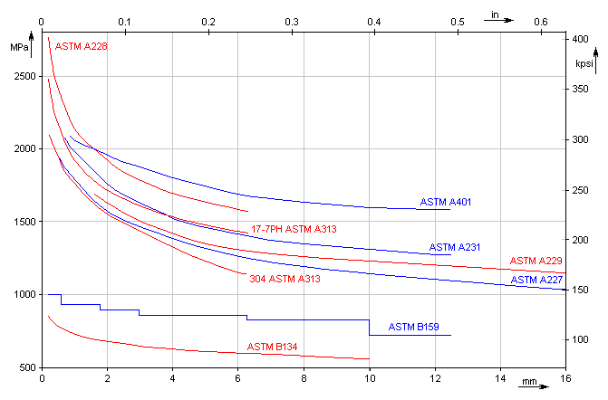
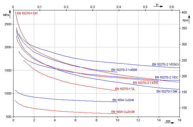
This paragraph is designed to set the operational and production parameters of the spring and to them related safety coefficients.
Set the corresponding operational conditions in the selection lists. The input field for entering the appropriate safety coefficient is situated to the right of each list. This coefficient expresses the influence of the given parameter on possible decrease in the load capacity of the spring.
Temperature of the working environment affects the spring relaxation, i.e. decrease in the force from the spring with its deformation to a constant length, depending on time. It is advisable to take this fact into account when designing the spring, and increase the level of safety during strength checks of the spring in case of temperatures over 80°C (180°F). It is necessary to respect the working temperature also with selection of the spring material.
As regards the strength check and the service life, there are the following two types of metal spring loads:
Choose the loading mode which best meets your entered data.
The service life of springs decreases significantly due to corrosion effects. Corrosion has very powerful effects particularly on springs exposed to fatigue loading. It is advisable to take this fact into account when designing the spring, and increase the level of safety during strength checks of the spring in case of a corrosion-aggressive environment. It is also necessary to consider corrosion effects with selection of the spring material.
Shot peening of the spring increases the fatigue limit by approx. 15 to 25%. In case of springs with shot peening exposed to fatigue loading, this allows users to reduce the consumption of material for production of the spring, reduce its dimensions and installation space, increase the working stroke or increase protection of the spring against fatigue breaks. Therefore, it is advisable to apply the technical requirement of shot peening to all springs exposed to oscillating loading.
Springs with galvanic coating have significantly higher corrosion resistance. On the other hand galvanic coating reduces the load capacity of the spring by about 10%.
It specifies the minimum permissible ratio between the limit permissible stress of the selected spring material and the actual stress of the spring at the maximum working load.
The required level of safety is used in the check calculation of strength of the statically loaded spring. The value specified here therefore actually eliminates any potential negative impact of the operational conditions on the spring load capacity decrease. Apart from the above mentioned facts the required value of safety should also incorporate some other factors (such as accuracy and reliability of input information, significance of the equipment, production quality, ...). Common springs are usually designed with the level of safety within the range of <1...2>.

Springs of cylindrical shape made of helically coiled wires, with constant clearance between the active coils, able to absorb external counter-acting forces applied against each other in their axis. Springs with wire diameter up to approx. 16 mm are usually cold wound. Hot forming shall be used for the production of heavily loaded springs of greater sizes with a diameter of the over 10 mm.
The way of design procedure used in this book allows to define dimensions of a spring with a certain degree of looseness. Therefore the exact value corresponding to the other parameters of the spring is calculated in real time for each of the input parameters. These values are displayed in green fields situated to the right of the input cells. Enter the calculated value in the input box using the appropriate "<" button.
The controls located in this paragraph serve for starting the design (optimization) functions of the calculation.
When designing the spring the calculation is trying to optimize the dimensions so that the wire diameter is as small as possible while keeping the required safety [1.27].
This paragraph specifies the results of the strength check of the designed spring. The check is carried out by comparing the permissible stress of the material used [1.20] with the actual stress of the fully loaded spring. The resulting level of safety [2.16] should not drop under the required value [1.27].
Lines [2.14, 2.15] are used to calculate theoretical values of the maximum working load and spring stroke where the required level of safety for the designed spring will still be met.
Select the required design of the spring ends from the list.
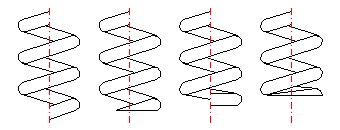
Set the corresponding length of the unloaded spring.
This paragraph specifies the basic working parameters of the designed spring in the prestressed (index 1), fully loaded (index 8) and limit condition (index 9).
| F | loading (force) of spring |
| s | spring deflection (compression) |
| L | spring length |
| t | torsional stress of the spring material |

Springs of cylindrical shape made of helically coiled wires, with constant clearance between the active coils, able to absorb external counter-acting forces applied against each other in their axis. Springs made of rectangular wire are cold wound. Hot forming shall be used for the production of heavily loaded springs of greater sizes with wire thickness of the over 10 mm.
The way of design procedure used in this book allows to define dimensions of a spring with a certain degree of looseness. Therefore the exact value corresponding to the other parameters of the spring is calculated in real time for each of the input parameters. These values are displayed in green fields situated to the right of the input cells. Enter the calculated value in the input box using the appropriate "<" button.
The controls located in this paragraph serve for starting the design (optimization) functions of the calculation.
When designing the spring the calculation is trying to optimize the dimensions so that the wire section is as small as possible while keeping the required safety [1.27].
This paragraph specifies the results of the strength check of the designed spring. The check is carried out by comparing the permissible stress of the material used [1.20] with the actual stress of the fully loaded spring. The resulting level of safety [3.17] should not drop under the required value [1.27].
Lines [3.15, 3.16] are used to calculate theoretical values of the maximum working load and spring stroke where the required level of safety for the designed spring will still be met.
Select the required design of the spring ends from the list.
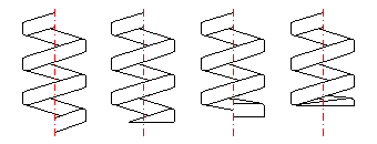
Set the corresponding length of the unloaded spring.
This paragraph specifies the basic working parameters of the designed spring in the prestressed (index 1), fully loaded (index 8) and limit condition (index 9).
| F | loading (force) of spring |
| s | spring deflection (compression) |
| L | spring length |
| t | torsional stress of the spring material |

Springs of conical shape made of helically coiled wires, with constant clearance between the active coils, able to absorb external counter-acting forces applied against each other in their axis. Springs with wire diameter up to approx. 16 mm are usually cold wound. Hot forming shall be used for the production of heavily loaded springs of greater sizes with a diameter of the over 10 mm.
With increasing compression of the conical spring, its active coils are brought into contact with adjacent coils gradually (first the coils with the largest diameter). These coils then do not participate in further compression of the spring which results in gradual increase in the spring constant. Working characteristics can therefore be divided into two areas:

The limit force FC depends on the selected size of free spring length L0. The limit force FC increases together with increasing spring length and the working area with linear spring constant rises.
The way of design procedure used in this book allows to define dimensions of a spring with a certain degree of looseness. Therefore the approximate value corresponding to the other parameters of the spring is calculated in real time for each of the input parameters. These values are displayed in green fields situated to the right of the input cells. Enter the calculated value in the input box using the appropriate "<" button.
Complexity of the conical spring design does not allow calculating all the spring parameters in real time. Therefore, after each change of the input data, it is necessary to start the calculation manually by pressing the "Calculate" button.
The controls located in this paragraph serve for starting the design (optimization) functions of the calculation. Spring design for the given ratios Dmax/Dmin, Dmin/d is started by moving one of the scroll bars. When designing the spring the calculation is trying to optimize the dimensions so that the wire diameter is as small as possible while keeping the required safety [1.27].
This paragraph specifies the results of the strength check of the designed spring. The check is carried out by comparing the permissible stress of the material used [1.20] with the actual stress of the fully loaded spring. The resulting level of safety [4.19] should not drop under the required value [1.27].
Lines [4.18] is used to calculate theoretical value of the maximum working load at which the level of safety for the designed spring will still be met.
This value specifies the maximum load (limit force) at which the spring will still work with constant stiffness (spring constant). The spring constant increases with growing load.
Select the required design of the spring ends from the list.
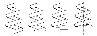
Set the corresponding length of the unloaded spring.
Free spring length considerably influences the maximum force value [4.21], and therefore also the working characteristic of the spring. The limit force increases together with increasing spring length, and the working area with the linear spring constant rises.
This paragraph specifies the basic working parameters of the designed spring in the prestressed (index 1), fully loaded (index 8) and limit condition (index 9).
| F | loading (force) of spring |
| s | spring deflection (compression) |
| L | spring length |
| t | torsional stress of the spring material |
| k | spring rate |

Springs of conical shape made of helically coiled wires, with constant clearance between the active coils, able to absorb external counter-acting forces applied against each other in their axis. Springs made of rectangular wire are cold wound. Hot forming shall be used for the production of heavily loaded springs of greater sizes with wire thickness of the over 10 mm.
With increasing compression of the conical spring, its active coils are brought into contact with adjacent coils gradually (first the coils with the largest diameter). These coils then do not participate in further compression of the spring which results in gradual increase in the spring constant. Working characteristics can therefore be divided into two areas:

The limit force FC depends on the selected size of free spring length L0. The limit force FC increases together with increasing spring length and the working area with linear spring constant rises.
The way of design procedure used in this book allows to define dimensions of a spring with a certain degree of looseness. Therefore the approximate value corresponding to the other parameters of the spring is calculated in real time for each of the input parameters. These values are displayed in green fields situated to the right of the input cells. Enter the calculated value in the input box using the appropriate "<" button.
Complexity of the conical spring design does not allow calculating all the spring parameters in real time. Therefore, after each change of the input data, it is necessary to start the calculation manually by pressing the "Calculate" button.
The controls located in this paragraph serve for starting the design (optimization) functions of the calculation. Spring design for the given ratios Dmax/Dmin, Dmin/b, b/h is started by moving one of the scroll bars. When designing the spring the calculation is trying to optimize the dimensions so that the wire section is as small as possible while keeping the required safety [1.27].
This paragraph specifies the results of the strength check of the designed spring. The check is carried out by comparing the permissible stress of the material used [1.20] with the actual stress of the fully loaded spring. The resulting level of safety [5.20] should not drop under the required value [1.27].
Lines [5.19] is used to calculate theoretical value of the maximum working load at which the level of safety for the designed spring will still be met.
This value specifies the maximum load (limit force) at which the spring will still work with constant stiffness (spring constant). The spring constant increases with growing load.
Select the required design of the spring ends from the list.
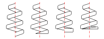
Set the corresponding length of the unloaded spring.
Free spring length considerably influences the maximum force value [5.22], and therefore also the working characteristic of the spring. The limit force increases together with increasing spring length, and the working area with the linear spring constant rises.
This paragraph specifies the basic working parameters of the designed spring in the prestressed (index 1), fully loaded (index 8) and limit condition (index 9).
| F | loading (force) of spring |
| s | spring deflection (compression) |
| L | spring length |
| t | torsional stress of the spring material |
| k | spring rate |

Annular rings of hollow truncated cone, able to absorb external axial forces counter-acting against each other. The spring section is usually rectangular. Springs of larger sizes (t > 6 mm) are sometimes made with machined contact flats.
Belleville springs are designed for higher loads with low deformations. They are used individually or in sets. When using springs in a set it is necessary to take account of friction effects. Friction in the set accounts for 3 – 5% of loading per each layer. Working load must then be increased by this force.
The shape of the Belleville spring characteristic curve is strongly affected by the relative height h0/t. For small values of the relative height the spring has nearly linear working characteristics; with rising ratio the characteristics are sharply degressive.

The way of design procedure used in this book allows to define dimensions of a spring with a certain degree of looseness. Therefore, to facilitate the design, the approximate values corresponding to the other parameters of the spring are calculated in real time for some of the input parameters. These values are displayed in green fields situated to the right of the input cells. Enter the calculated value in the input box using the appropriate "<" button.
Select the permissible proportionate spring deflection in the selection list.
In the case of statically loaded springs the operating deflection of the spring should not exceed 75 – 80% of the maximum (full) deflection [6.19]. In the springs with cyclic (fatigue) loading 50% value is usually accepted.
Discs arranged in the same direction.

Discs or disc sets arranged against each other.
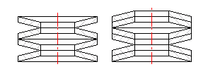
Complexity of the Belleville spring design does not allow calculating all the spring parameters in real time. Therefore, after each change of the input data, it is necessary to start the calculation manually by pressing the "Calculate" button.
In the selection list you will find the database of the Belleville springs with commonly manufactured dimensions. Spring dimensions in the list are specified as "De x Di x t x h".
This paragraph serves for automatic design (finding) of a Belleville spring of satisfactory dimensions.
In the selection lists set the permissible deviation from the required working stroke of the spring [6.4] and maximum permissible numbers of discs in a set. After pressing the "Find first" button the program will find the first spring from the list [6.14], which meets all the specified requirements while keeping the minimum safety. If the selected spring does not meet your expectations, use the "Find next" button to find a spring of different dimensions.
Theoretically determined value of the maximum working loading at which the maximum compressive stress [6.31] of the designed spring does not exceed the permissible limit [6.30] while satisfying the permissible spring deflection at the same time [6.5].
Stress occurring in the Belleville spring is rather complex. Maximum stress (compressive) develops in the inner top edge. Tensile stress occurs on the bottom outer edge. Maximum compressive stress serves for strength check of springs subjected to static loading. In the springs subjected to cyclic (fatigue) loading the pattern of tensile stresses is checked.
This paragraph specifies the results of the strength check of a statically loaded spring. The check is carried out by comparing the permissible stress of the material used [6.30] with the maximum compressive stress of a fully loaded spring [6.31]. The resulting level of safety [6.34] should not drop under the recommended value [6.33].
Enter the permissible compressive stress of the spring material.
Recommended level of safety for the selected material [1.6] is estimated based on the operational conditions defined in paragraph [1.21].
This paragraph specifies the basic working parameters of the designed spring in the prestressed (index 1), fully loaded (index 8) and limit condition (index 9).
| F | loading (force) of spring |
| s | spring deflection (compression) |
| L | spring length |
| sP | max. compressive stress |
| k | spring rate |

Springs of cylindrical shape made of helically coiled wires, with constant clearance between the active coils, able to absorb external axial forces counter-acting from each other. Springs with wire diameter up to approx. 16 mm are usually cold wound. Hot forming shall be used for the production of heavily loaded springs of greater sizes with a diameter of the over10 mm.
Tension springs are used in two basic designs:
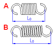
The way of design procedure used in this book allows to define dimensions of a spring with a certain degree of looseness. Therefore the exact value corresponding to the other parameters of the spring is calculated in real time for each of the input parameters. These values are displayed in green fields situated to the right of the input cells. Enter the calculated value in the input box using the appropriate "<" button.
The controls located in this paragraph serve for starting the design (optimization) functions of the calculation.
When designing the spring the calculation is trying to optimize the dimensions so that the wire diameter is as small as possible while keeping the required safety [1.27].
This paragraph specifies the results of the strength check of the designed spring. The check is carried out by comparing the permissible stress of the material used [1.20] with the actual stress of the fully loaded spring. The resulting level of safety [7.18] should not drop under the required value [1.27].
Lines [7.16, 7.17] are used to calculate theoretical values of the maximum working load and spring stroke where the required level of safety for the designed spring will still be met.
Select the required design of the spring ends from the list.
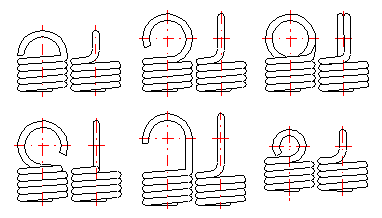
Loading of the spring creates a concentration of stress in the fixing eyes and this may be substantially higher than the calculated stress in the spring coils. This is why sometimes a different way of spring attachment is used.
The height of the spring hook depends on its type and for individual types, their recommended limits are prescribed. In case of springs without fixing eyes, this term means the distance between the end of active coils and the point of fixing of the spring (see the illustration).
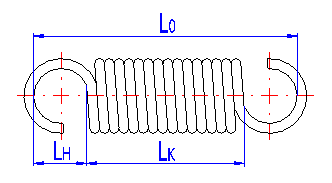
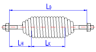
Initial stress appears in coils of the spring in the course of coiling of the spring wire, and its size depends on the used material, spring index and the manner of coiling. The initial stress will be zero for springs with spaces between its coils.
Enter the free spring length for a spring without initial stress.
This paragraph specifies the basic working parameters of the designed spring in the prestressed (index 1), fully loaded (index 8) and limit condition (index 9).
| F | loading (force) of spring |
| s | spring deflection (extension) |
| L | spring length |
| t | torsional stress of the spring material |

Springs of cylindrical shape made of helically coiled wires, with constant clearance between the active coils, able to absorb external axial forces counter-acting from each other. Springs made of rectangular wire are cold wound. Hot forming shall be used for the production of heavily loaded springs of greater sizes with wire thickness of the over 10 mm.
The way of design procedure used in this book allows to define dimensions of a spring with a certain degree of looseness. Therefore the exact value corresponding to the other parameters of the spring is calculated in real time for each of the input parameters. These values are displayed in green fields situated to the right of the input cells. Enter the calculated value in the input box using the appropriate "<" button.
The controls located in this paragraph serve for starting the design (optimization) functions of the calculation.
When designing the spring the calculation is trying to optimize the dimensions so that the wire section is as small as possible while keeping the required safety [1.27].
This paragraph specifies the results of the strength check of the designed spring. The check is carried out by comparing the permissible stress of the material used [1.20] with the actual stress of the fully loaded spring. The resulting level of safety [8.17] should not drop under the required value [1.27].
Lines [8.15, 8.16] are used to calculate theoretical values of the maximum working load and spring stroke where the required level of safety for the designed spring will still be met.
Due to high concentrations of stress occurring in the hook, the springs made of rectangular wire usually use different way of spring fixing.

The height of the spring hook depends on its type and for individual types, their recommended limits are prescribed. In case of springs without fixing eyes, this term means the distance between the end of active coils and the point of fixing of the spring (see the illustration).
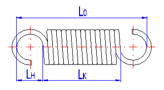
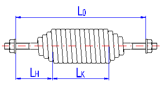
Set the corresponding length of the unloaded spring.
This paragraph specifies the basic working parameters of the designed spring in the prestressed (index 1), fully loaded (index 8) and limit condition (index 9).
| F | loading (force) of spring |
| s | spring deflection (extension) |
| L | spring length |
| t | torsional stress of the spring material |

The spring made of a strip with rectangular section wound into the shape of Archimedes spiral, with constant spacing between its active coils, loaded with torque in the direction of the winding.
The way of design procedure used in this book allows to define dimensions of a spring with a certain degree of looseness. Therefore the exact value corresponding to the other parameters of the spring is calculated in real time for each of the input parameters. These values are displayed in green fields situated to the right of the input cells. Enter the calculated value in the input box using the appropriate "<" button.
The controls located in this paragraph serve for starting the design (optimization) functions of the calculation. Spring design for the given ratios Ri/t, b/t, a0/t is started by moving one of the scroll bars. When designing the spring the calculation is trying to optimize the dimensions so that the strip thickness is as small as possible while keeping the required safety [1.27].
This paragraph specifies the results of the strength check of the designed spring. The check is carried out by comparing the permissible stress of the material used [1.20] with the actual stress of the fully loaded spring. The resulting level of safety [9.18] should not drop under the required value [1.27].
Lines [9.16, 9.17] are used to calculate theoretical values of the maximum working load and spring stroke where the required level of safety for the designed spring will still be met.
This paragraph specifies the basic working parameters of the designed spring in the prestressed (index 1), fully loaded (index 8) and limit condition (index 9).
| M | loading (torque) of spring |
| n | number of active coils |
| a | angular deflection (twisting) of spring |
| d | leg angle |
| s | bending stress of the spring material |

Springs of cylindrical shape made of helically coiled wires, with constant spacing between the active coils, able to absorb external forces applied in the planes perpendicular to the winding axis through a torque in the direction of winding or unwinding. Springs with wire diameter up to approx. 16 mm are usually cold wound. Hot forming shall be used for the production of heavily loaded springs of greater sizes with a diameter of the over 10 mm.
Torsion springs are produced in two basic designs: tight-coiled and loose-coiled (with clearance between the coils). If the springs are exposed to a static loading, the tight-coiled springs are recommended. Loose-coiled springs are suitable for use with fatigue loading.
The way of design procedure used in this book allows to define dimensions of a spring with a certain degree of looseness. Therefore the exact value corresponding to the other parameters of the spring is calculated in real time for each of the input parameters. These values are displayed in green fields situated to the right of the input cells. Enter the calculated value in the input box using the appropriate "<" button.
The controls located in this paragraph serve for starting the design (optimization) functions of the calculation.
When designing the spring the calculation is trying to optimize the dimensions so that the wire diameter is as small as possible while keeping the required safety [1.27].
This paragraph specifies the results of the strength check of the designed spring. The check is carried out by comparing the permissible stress of the material used [1.20] with the actual stress of the fully loaded spring. The resulting level of safety [10.16] should not drop under the required value [1.27].
Lines [10.14, 10.15] are used to calculate theoretical values of the maximum working load and spring stroke where the required level of safety for the designed spring will still be met.
Select the required design of the spring ends from the list.

Set the corresponding length of coiled section.
Functional deformation (shift of the arm) of the torsional spring leads to the change of its dimensions. The diameter of springs loaded in the direction of coil winding decreases during its loading. In addition, the length of close wound spring grows.
This paragraph specifies the basic working parameters of the designed spring in the prestressed (index 1), fully loaded (index 8) and limit condition (index 9).
| M | loading (torque) of spring |
| a | angular deflection (twisting) of spring |
| d | leg angle |
| s | bending stress of the spring material |

Springs of cylindrical shape made of helically coiled wires, with constant spacing between the active coils, able to absorb external forces applied in the planes perpendicular to the winding axis through a torque in the direction of winding or unwinding. Springs made of rectangular wire are cold wound. Hot forming shall be used for the production of heavily loaded springs of greater sizes with wire thickness of the over 10 mm.
Torsion springs are produced in two basic designs: tight-coiled and loose-coiled (with clearance between the coils). If the springs are exposed to a static loading, the tight-coiled springs are recommended. Loose-coiled springs are suitable for use with fatigue loading.
The way of design procedure used in this book allows to define dimensions of a spring with a certain degree of looseness. Therefore the exact value corresponding to the other parameters of the spring is calculated in real time for each of the input parameters. These values are displayed in green fields situated to the right of the input cells. Enter the calculated value in the input box using the appropriate "<" button.
The controls located in this paragraph serve for starting the design (optimization) functions of the calculation.
When designing the spring the calculation is trying to optimize the dimensions so that the wire thickness is as small as possible while keeping the required safety [1.27].
This paragraph specifies the results of the strength check of the designed spring. The check is carried out by comparing the permissible stress of the material used [1.20] with the actual stress of the fully loaded spring. The resulting level of safety [11.17] should not drop under the required value [1.27].
Lines [11.15, 11.16] are used to calculate theoretical values of the maximum working load and spring stroke where the required level of safety for the designed spring will still be met.
Select the required design of the spring ends from the list.

Set the corresponding length of coiled section.
Functional deformation (shift of the arm) of the torsional spring leads to the change of its dimensions. The diameter of springs loaded in the direction of coil winding decreases during its loading. In addition, the length of close wound spring grows.
This paragraph specifies the basic working parameters of the designed spring in the prestressed (index 1), fully loaded (index 8) and limit condition (index 9).
| M | loading (torque) of spring |
| a | angular deflection (twisting) of spring |
| d | leg angle |
| s | bending stress of the spring material |

Springs based on the principle of long slender bars of circular section subjected to torsion. The ends of bars are mostly fixed by means of grooving. Sometimes one end is square-shaped in order to facilitate attachment.
The way of design procedure used in this book allows to define dimensions of a spring with a certain degree of looseness. Therefore the exact value corresponding to the other parameters of the spring is calculated in real time for each of the input parameters. These values are displayed in green fields situated to the right of the input cells. Enter the calculated value in the input box using the appropriate "<" button.
When pressing the button you will design a spring of satisfactory dimensions. When designing the spring the calculation is trying to optimize the dimensions so that the bar diameter is as small as possible while keeping the required safety [1.27].
This paragraph specifies the results of the strength check of the designed spring. The check is carried out by comparing the permissible stress of the material used [1.20] with the actual stress of the fully loaded spring. The resulting level of safety [12.15] should not drop under the required value [1.27].
Lines [12.13, 12.14] are used to calculate theoretical values of the maximum working load and spring stroke where the required level of safety for the designed spring will still be met.
This paragraph specifies the basic working parameters of the designed spring in the prestressed (index 1), fully loaded (index 8) and limit condition (index 9).
| M | loading (torque) of spring |
| a | angular deflection (twisting) of spring |
| t | torsional stress of the spring material |

Springs based on the principle of long slender bars of rectangular section subjected to torsion.
The way of design procedure used in this book allows to define dimensions of a spring with a certain degree of looseness. Therefore the exact value corresponding to the other parameters of the spring is calculated in real time for each of the input parameters. These values are displayed in green fields situated to the right of the input cells. Enter the calculated value in the input box using the appropriate "<" button.
The controls located in this paragraph serve for starting the design (optimization) functions of the calculation.
When designing the spring the calculation is trying to optimize the dimensions so that the bar thickness is as small as possible while keeping the required safety [1.27].
This paragraph specifies the results of the strength check of the designed spring. The check is carried out by comparing the permissible stress of the material used [1.20] with the actual stress of the fully loaded spring. The resulting level of safety [13.16] should not drop under the required value [1.27].
Lines [13.14, 13.15] are used to calculate theoretical values of the maximum working load and spring stroke where the required level of safety for the designed spring will still be met.
This paragraph specifies the basic working parameters of the designed spring in the prestressed (index 1), fully loaded (index 8) and limit condition (index 9).
| M | loading (torque) of spring |
| a | angular deflection (twisting) of spring |
| t | torsional stress of the spring material |

Springs based on the principle of long slander beams of rectangular section subjected to bending. They are used as cantilever springs (fixed at one end), or as simple beams (fixed at both ends). Springs of rectangular, triangular or trapezoidal shape are used.
The way of design procedure used in this book allows to define dimensions of a spring with a certain degree of looseness. Therefore the exact value corresponding to the other parameters of the spring is calculated in real time for each of the input parameters. These values are displayed in green fields situated to the right of the input cells. Enter the calculated value in the input box using the appropriate "<" button.
The controls located in this paragraph serve for starting the design (optimization) functions of the calculation.
When designing the spring the calculation is trying to optimize the dimensions so that the leaf thickness is as small as possible while keeping the required safety [1.27].
This paragraph specifies the results of the strength check of the designed spring. The check is carried out by comparing the permissible stress of the material used [1.20] with the actual stress of the fully loaded spring. The resulting level of safety [14.19] should not drop under the required value [1.27].
Lines [14.17, 14.18] are used to calculate theoretical values of the maximum working load and spring stroke where the required level of safety for the designed spring will still be met.
This paragraph specifies the basic working parameters of the designed spring in the prestressed (index 1), fully loaded (index 8) and limit condition (index 9).
| F | loading (force) of spring |
| s | spring deflection |
| s | bending stress of the spring material |
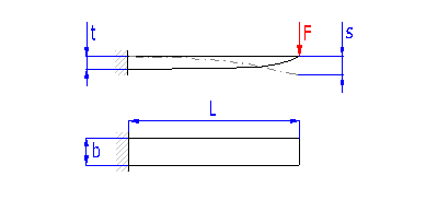
Springs based on the principle of long slander beams of rectangular section subjected to bending. They are used as cantilever springs (fixed at one end), or as simple beams (fixed at both ends). Usually of rectangular shape, sometimes springs thicker in the middle and at the end of the leaf are used
The way of design procedure used in this book allows to define dimensions of a spring with a certain degree of looseness. Therefore the exact value corresponding to the other parameters of the spring is calculated in real time for each of the input parameters. These values are displayed in green fields situated to the right of the input cells. Enter the calculated value in the input box using the appropriate "<" button.
The controls located in this paragraph serve for starting the design (optimization) functions of the calculation.
When designing the spring the calculation is trying to optimize the dimensions so that the leaf thickness is as small as possible while keeping the required safety [1.27].
This paragraph specifies the results of the strength check of the designed spring. The check is carried out by comparing the permissible stress of the material used [1.20] with the actual stress of the fully loaded spring. The resulting level of safety [15.19] should not drop under the required value [1.27].
Lines [15.17, 15.18] are used to calculate theoretical values of the maximum working load and spring stroke where the required level of safety for the designed spring will still be met.
This paragraph specifies the basic working parameters of the designed spring in the prestressed (index 1), fully loaded (index 8) and limit condition (index 9).
| F | loading (force) of spring |
| s | spring deflection |
| s | bending stress of the spring material |
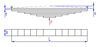
Springs based on the principle of a bunch of long slander beams of rectangular section subjected to bending.
The way of design procedure used in this book allows to define dimensions of a spring with a certain degree of looseness. Therefore the exact value corresponding to the other parameters of the spring is calculated in real time for each of the input parameters. These values are displayed in green fields situated to the right of the input cells. Enter the calculated value in the input box using the appropriate "<" button.
Spring leaves of full length, rectangular shape with constant profile. These leaves are added to the spring for two reasons:

The controls located in this paragraph serve for starting the design (optimization) functions of the calculation.
When designing the spring the calculation is trying to optimize the dimensions so that the leaf thickness is as small as possible while keeping the required safety [1.27].
This paragraph specifies the results of the strength check of the designed spring. The check is carried out by comparing the permissible stress of the material used [1.20] with the actual stress of the fully loaded spring. The resulting level of safety [16.19] should not drop under the required value [1.27].
Lines [16.17, 16.18] are used to calculate theoretical values of the maximum working load and spring stroke where the required level of safety for the designed spring will still be met.
This paragraph specifies the basic working parameters of the designed spring in the prestressed (index 1), fully loaded (index 8) and limit condition (index 9).
| F | loading (force) of spring |
| s | spring deflection |
| s | bending stress of the spring material |
This paragraph is designed to carry out the strength check of springs subjected to cyclic (fatigue) loading, i.e. the springs with the service life requirement higher than 105 of working cycles. The check is carried out by comparing the permissible stress of the material used [17.8] with the actual stress of a fully loaded spring [17.4].
If the spring does not satisfy the endurance check, repeat its design while adhering to the following recommendations:
Two fields of fatigue loading of springs can be distinguished with springs exposed to fatigue loading. In the first field, with limited service life of springs (lower than approx. 107 working cycles, the fatigue strength of the spring decreases with an increasing number of working cycles. In the field of unlimited service life (the desired service life of the spring is higher than 107 working cycles), the fatigue limit of the material and thus the strength of the spring remains approximately constant.
Set the maximum permissible stress of the spring material for infinite life and zero-to-maximum stress fluctuation. If the check box to the right of the input field is selected, the minimum value of fatigue strength specified for the selected material will be set automatically here [1.6] as well as the selected surface treatment of the spring [1.26].
Determination of the maximum fatigue strength of the spring is based on the ultimate fatigue strength of the chosen material and the given course of loading of the spring using a Goodman's fatigue diagram.
Recommended level of safety for the selected material [1.6] is estimated based on the operational conditions defined in paragraph [1.21].
Information on setting of calculation parameters and setting of the language can be found in the document "Setting calculations, change the language".
General information on how to modify and extend calculation workbooks is mentioned in the document "Workbook (calculation) modifications".
^