The calculation concerns solutions of pressure vessels and their components. The calculation solves deformations and curves of stress in rotational shells loaded with axial force, pressure, radial force and a bending moment. This program is intended for homogeneous shells of identical thickness and a single material. The calculation also enables solutions for connecting two shells of different parameters (thickness, material, dimensions...). The program enables:
The calculation uses the data, procedures, algorithms and information from the professional literature (Roark formulas, Machinery's Handbook 26th, Teorie desek a skoøepin [doc. Ing. Ladislav Šubrt, CSc.] and others)
User interface.
Download.
Purchase, Price list.
Information on the syntax and control of the calculation can be found in the document "Control, structure and syntax of calculations".
Information on the purpose, use and control of the paragraph "Information on the project" can be found in the document "Information on the project".
The shells can be divided according to their shape as:
The shells can be divided according to their thickness as:
The shell thickness is comparable with the minimum radius of curvature. In these shells, neither direct stress perpendicular to the mid-surface area, nor bending of the normals to the central area caused by shear forces should be neglected.They cause non-linear distribution of stress along the thickness of the shell. This fact causes a complicated analytic solution, so a finite element method is mostly used in these shells.
This type of shell lies between thick and thin-wall shells, for which the thick-wall theory is too complicated and the thin-wall shell theory does not provide sufficiently accurate results.
These shells have a very thin wall with regard to the minimal radius of curvature. It is possible to neglect the impact of shear stress on deformation of the normals to the mid-surface area. This, together with the possibility to neglect some other stresses leads to a simpler analytic solution of this type of shell. This type of rotation shell is solved by this calculation.
These very thin shells are subject to deformation comparable to or higher than the thickness of the wall, which leads to a change of the point of force application in the course of loading. An analytic solution is rather complicated, so a finite element method is mostly used for solving these shells.
Membranes are shells where no internal moments are present (bend, shear). They are only stressed with direct or perhaps shear forces, which leads to an even distribution of stress along the wall thickness. The membrane stress is an advantage as regards utilisation of the material; it is thus important to make sure this condition is not greatly affected by unsuitable construction in the structural design.
Analytic solution of thin-wall shells is based on an element extracted from the basic shell; see the figure.

As thick-wall shells are not considered, it is possible to apply linear curves of the normal (s1, s2) as well as shear (t12, t21) stresses. In the shells, these stresses are non-zero in the mid-surface area, so it concerns a superposition (composition) of the bend and tension, or rather superposition of torsion and an evenly distributed shear. For example, stress s1 is thus composed of a membrane and bend stress.
For this element, the stress is then replaced with internal force effects according to the following table:
| Force | Resulting internal force effect |
| s1 | N1-normal force |
| M1-bending moment | |
| s2 | N2-normal force |
| M2-bending moment | |
| t12 | S12-shear force |
| M12-torque | |
| t21 | S21-shear force |
| M21-torque | |
| t13 | Q1-vertical shear |
| t31 | Q2-vertical shear |
Since the extracted element must be in balance, it is possible to make a set
of equations of equilibrium for a set of forces affecting the element. It is
also necessary to derive relations for deformation of the shell and relations
determining dependency between deformations and internal force effects.
In a general sense, the solving of these equations leads to a complicated, hard to solve set of partial differential equations. Consequently, various simplifying conditions are adopted for particular types of shells, which leads to approximate, but sufficiently accurate results that satisfy the practical purposes.
The particular sets of differential equations are always supplemented with corresponding boundary conditions.
It is possible to find solutions for various types of shells in books by various authors. The resulting sets of equations often differ (in relation to the adopted simplifications), but the results of solutions by the various equations differ very slightly (the estimated variance is up to 10%).
The following conditions apply for solving thin-wall shells:
Rotational, or rather rotationally symmetrical shells are probably the most frequent shells in the technical practice.
Rotational shells are shells whose mid-surface area is rotational and no restrictive conditions are specified for the stress. The conventional solution of rotational shells is again complicated and is elaborated mainly for a cylindrical shell, which is probably the most widely used type of shell.
Rotationally symmetrical shells are rotational shells, which are stressed constantly along parallel circles. The solution of this type of shell is much simpler, depending on a single coordinate. It is possible to find solutions for basic geometrical shapes of shells such as cylinder, sphere, cone, torus, etc.
This program is particularly intended for solving rotationally symmetrical shells.
Shell structures are usually structures formed by connecting two or more shells or connecting shells to other structural elements. A typical example is a cylindrical pressure vessel with a spherical bottom, reduction of the pipe diameter by a cone adaptor or a flange on a cylindrical pipe.
We can regard these cases statically undetermined. It means that force effects that occur in a joint between two shells cannot be solved by static equations of equilibrium. Everything can be explained on the following examples showing a connection of a cylindrical and spherical shell stressed with internal overpressure.
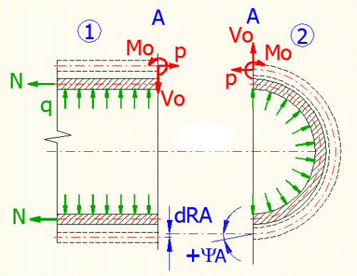
If we stressed the individual shells, only membrane stress would occur and the shells would deform into the illustrated shape (dash line). In the joint area between the two shells, the radiuses would change by an unequal value and the wall of the spherical shell would axially shift. This problem is usually solved by force method, where we attach an unspecified force "Vo", a moment "Mo" and a force "p" to the periphery of each shell.
To be able to "join" the shells, it is necessary to define deformation conditions that ensure that the resulting deformation of both shells is identical. By solving these equations it is then possible to solve deformations and stress in the joint between the shells, which is usually a point with a local peak stress, which interests us.
The shell is in the so-called membrane condition if there are no moments, but only internal forces in the shell. This condition is suitable and desirable as regards the stress capacity of the shell. Whether the shell is in a membrane condition depends on its shape, lodgement method and stress. There are two basic rules for designing a shell which is in the membrane condition:
If these conditions are not satisfied, the membrane condition is disturbed, the stress rises and must be compensated with a larger thickness of the wall. Various reinforcements or props are thus often used to absorb unsuitable stress that might disturb the membrane condition.
When solving the deformation (stress) of the actual shell, proceed as follows:
1...Choose a material for the shell, i.e. enter the material values
[1.0]
2...Select the appropriate section of the calculation
[2.0, 3.0, 4.0, 5.0]
3...Select the loading method [2.1, 3.1, 4.1, 5.1]
4...Enter the dimensions and stress on the shell and check the results
When solving deformation (stress) in joint shells, proceed as follows:
1...Select the type of joint between the shells
[10.1] and confirm with OK
2...Sections containing the selected shells [6.0, 7.0,
8.0, 9.0] are displayed in accordance with the selection
3...Enter the material values, dimensions and stress of the shells
4...Push the "Solve" button in section [10.0]
and start the iteration
5...Check the results in sections with the selected shells
In this section, select the calculation units and choose the material of the inspected shell. The material values are automatically used in the sections [2.0-5.0]. In sections [6.0-9.0], it is possible to assign different material parameters to each shell.
Use the drop-down menu to choose the required system of units for the calculation. After the units are switched, all values will be re-calculated immediately.
Use the drop-down menu to choose the proper shell material. If the material constants of your material differ from the material constants specified on line [1.3 - 1.8], uncheck the check box on line [1.3] and set the customized material properties.
This calculation can detect the stress and deformation of variously loaded thin-wall cylindrical shell. T<R/10 must apply for each shell thickness. The deformation of the shell should be small in relation to the thickness.
Choose a stress that corresponds to your problem in the select list. A schematic chart of the stress appears after the selection. The validity conditions appear to the right of the select list.
Notes for individual loading cases:
3. In a point sufficiently distant from the edge.
4. Where "y" must be measured from the unloaded end
Enter the shell thickness, the radius of the curvature (middle radius) and its length. The shell thickness should be smaller than 1/10 of the radius.
You can choose between entering the total force or a force related to one millimetre (inch) of the perimeter. Select the desired method from a button on this line. After switching, the value in the input field is automatically calculated according to the actual diameter.
Enter the internal overpressure. In case of external overpressure, enter a negative value.
Enter the rotation speed of the shell in rounds per minute.
These lines provide the results of the calculation.
This calculation can detect the stress and deformation of variously loaded thin-wall conical shell. T<R/10 (t<r/10) must apply for each shell thickness. The deformation of the shell should be small in relation to the thickness.
Choose a stress that corresponds to your problem in the select list. A schematic chart of the stress appears after the selection. The validity conditions appear to the right of the select list.
Notes for individual loading cases:
2...There is a discreteness in a pressure stress from
a liquid under and over the surface. This leads to a bending stress in this
area. For "y" lying under the liquid surface (y<d), s1max
is in the height of y=3*d/4 and for s2max
in the height of Y=d/2.
4...The "r" must be a positive value and "r/t>10", to
maintain the condition of a thin-wall vessel.
Enter the shell thickness [3.2]. As the diameter, length and angle of the cone are mutually dependent variables, select which of the variables will be the input variables on the line [3.3]. Then enter these dimension values.
If a tangential stress method is selected on line [3.1], (selection-4), it is possible to enter all three values (R,y,a) and the dependent variable is the second diameter "r".
Enter the depth of filling and the specific mass of the liquid.
You can choose between entering the total force or a force related to one millimetre (inch) of the perimeter. Select the desired method from a button on this line. After switching, the value in the input field is automatically calculated according to the actual diameter.
Enter the internal overpressure. In case of external overpressure, enter a negative value.
Enter the rotation speed of the shell in rounds per minute.
These lines provide the results of the calculation.
This calculation can detect the stress and deformation of variously loaded thin-wall shells. t<R2/10 must apply for each shell thickness. The deformation of the shell should be small in relation to the thickness.
Choose a stress that corresponds to your problem in the select list. A schematic chart of the stress appears after the selection. The validity conditions appear to the right of the select list.
Notes for individual loading cases:
2... There is a discreteness in a pressure stress from
a liquid under and over the surface. This leads to a bending stress in this
area. The calculation is valid for "y" lying under the surface (y<d). For y>d,
load 4 is used, where the force is derived by the mass of the liquid.
4... The angle "q0" is an
angle to the bottom edge of the vessel, which must be larger than zero.
5... For the angle "q"<=90
deg.
Enter the thickness [4.2] and middle radius of the spherical shell [4.3], the angle from the shell to the top edge [4.4] and, if necessary, the angle from the shell axis to the bottom edge [4.5].
Enter the depth of filling and the specific mass of the liquid.
You can choose between entering the total force or a force related to one millimetre (inch) of the perimeter. Select the desired method from a button on this line. After switching, the value in the input field is automatically calculated according to the actual diameter.
Enter the internal overpressure. In case of external overpressure, enter a negative value.
Enter the rotation speed of the shell in rounds per minute.
These lines provide the results of the calculation.
This calculation can detect the stress and deformation of variously loaded thick-wall cylindrical or spherical shells.
Choose a stress that corresponds to your problem in the select list. A schematic chart of the stress appears after the selection. The validity conditions appear to the right of the select list.
Enter the external and internal radius of the shell [5.2, 5.3] and, if necessary, the length of the shell [5.4].
Enter the load per unit of area [5.5].
These lines provide the results of the calculation. You can also change the radius on which the calculated stress values will be specified on the line [5.15].
This calculation can detect the stress and deformation of variously loaded long thin-wall shells. t<R/10 must apply for each shell thickness. The deformation of the shell should be small in relation to the thickness. When loading the shell with the end moment "Mo" and the force "Vo", the stress (deformations) will have a oscillatory character suppressed by the exponent line (see the figure).
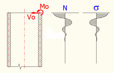
This means that the effects of these loads quickly dissipate and will not occur in a sufficient distance from the edge. This is why cylindrical shells are divided as long (loading of one edge will not affect deformations and stress of the other edge) and short (the effects of the edge load have no time to dissipate and affect the stress of the other edge). A cylindrical shell can be regarded long if its length is larger than the L value, which is given on the line [6.2] in the conditions. If we accept a lower accuracy (the error of the solution will no larger than 10%), it is possible to consider a half of the L value.
Formula for the calculation L:
L=6/(3*(1-ny^2)/(R^2*t^2))^(1/4); where:
ny...Poisson constant
R....External radius
t.....Shell thickness
The first part of the calculation involves input data, the other the results. In the top right area, you can find the most important boundary conditions; underneath, there are pictures of the dimensioned shell and its stress. Choose between the figures using the ">" button in the top right corner of the picture.
If the check box to the right of the input field is checked, the material constants are transferred from section [1.0]. If you need to enter your own values, check the box and enter the modulus of elasticity in tension [6.2] and the Poisson constant [6.3].
Enter the middle radius [6.4] and the thickness of the cylindrical shell [6.5].
Enter the stress per unit of area [6.6]. If the
shell is stressed with internal overpressure, the value is positive; if the
overpressure is external, enter a negative value. The line
[6.7] then specifies the total axial force, which occurs by action of the
entered pressure on the surface of the round base.
Enter the force related to the unit of length "p" on the line
[6.8], or the total force "P". You can choose between entering the total
force or the force related to one millimetre (inch) of the circumference. Select
the desired method from a button on this line. After switching, the value in the
input field is automatically calculated according to the actual diameter. If you
push the "<-Pq" button, the value from line
[6.7] is transferred to this input field.
Enter the circumferential force (perpendicular to the shell axis) on the line
[6.9] and the moment on the line [6.10].
The line [6.12, 6.13]
specifies deformations of the shell on its border (x=0). The line
[6.14] includes an input field for the "x" coordinate (measured from the
edge of the shell in the direction of its axis). Below you will find individual
results for the entered "x" coordinate. You can change the "x" coordinate with a
scroll bar; its range is from zero to the value given to the right of the scroll
bar (the minimum length of the shell is pre-set).
The line [6.15] includes a select list where you can
choose which input stress (or their sum) the results will be given for.
The functionality of the second calculation is identical with the first calculation.
This calculation can detect the stress and deformation of a variously loaded thin-wall spherical shell. t<R/10 must apply for each shell thickness. The deformation of the shell should be small in relation to the thickness. When loading the shell with the end moment "Mo" and the force "Vo", the stress (deformations) will have a oscillatory character suppressed by the exponent line (see the figure).
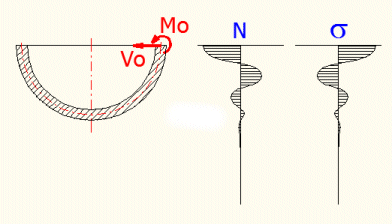
This means that the effects of these loads quickly dissipate and will not occur in a sufficient distance from the edge.
The first part of the calculation involves input data, the other the results. In the top right area, you can find the most important boundary conditions; underneath, there are pictures of the dimensioned shell and its stress. Choose between the figures using the ">" button in the top right corner of the picture.
If the check box to the right of the input field is checked, the material constants are transferred from section [1.0]. If you need to enter your own values, check the box and enter the modulus of elasticity in tension [7.2] and the Poisson constant [7.3].
Enter the angle measured from the axis of the shell to its edge "f" [7.4] and the shell thickness [7.5]. Then enter the middle radius of the spherical shell "R2" [7.6] or the radius "R" [7.7] (the distance from the axis to the edge). You can choose the value that you want to enter in the select list on the line [7.6]. The other value will be calculated.
Enter the load per unit of area [7.8]. If the shell is stressed with internal overpressure, the value is positive; if the overpressure is external, enter a negative value. The line [7.8] then specifies the total tangential force, which occurs by action of the entered pressure on the surface of the round base and its distribution into the x and y co-ordinate [7.10, 7.11].
Enter the force related to the unit of length "P" on the line [7.12], or the total force "p". You can choose between entering the total force or a force related to one millimetre (inch) of the perimeter. Select the desired method from a button on this line. After switching, the value in the input field is automatically calculated according to the actual diameter. If you push the "<-Pq" button, the value from line [7.9] is transferred to this input field.
Enter the circumferential force (perpendicular to the shell axis) on the line [7.13] and the moment on the line [7.14].
The line [7.16, 7.17] specifies deformations of the shell on its border(w=0). The line [7.18] contains an input field for the angle w (measured from the edge of the shell). The individual results for the entered angle w are as follows. You can change the w angle with a scroll bar; its range is from zero to the value given to the right of the scroll bar.
The line [7.19] includes a select list where you can choose which input stress (or their sum) the results will be given for.
The functionality of the second calculation is identical with the first calculation.
Enter the angle measured from the axis of the shell to its edge "f" [7.33] and the shell thickness [7.34]. Then enter the middle radius of the spherical shell "R2" [7.35] or the radius "R" [7.36] (the distance from the axis to the edge). You can choose the value that you want to enter in the select list on the line [7.35]. The other value will be calculated.
With the two "<-f" buttons to the right of the line [7.33], you can enter such "f" angle that ensures an identical radius "R" [7.35] with "R" [7.6]. It will thus enable an accurate "connection" with the spherical shell of the First Calculation.
This calculation can detect the stress and deformation of variously loaded long thin-wall conical shells. t<R/10 must apply for each shell thickness. The deformation of the shell should be small in relation to the thickness. When loading the shell with the end moment "Mo" and the force "Vo", the stress (deformations) will have a oscillatory character suppressed by the exponent line (see the figure).
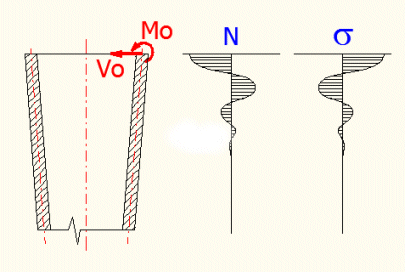
This means that the effects of these loads quickly dissipate and will not occur in a sufficient distance from the edge. This is why conical shells are divided as long (loading of one edge will not affect deformations and stress of the other edge) and short (the effects of the edge load have no time to dissipate and affect the stress of the other edge). A conical shell can be regarded long if its length is larger than the L value, which is given on the line[8.2] in the conditions.
For the L calculation (an area where the effects of the boundary stress are
sufficiently suppressed), the following relations are used:
1) coefficient k=2/sin(a)*((12*(1-ny^2)*R^2)/(t^2*(1/cos(a))^2))^(1/4)
2) coefficient mi=abs((kA-k)/(2^0.5))
3) R=RA-x*tan(a)
4) the area with sufficient suppression is considered
if the coefficient mi=4.
where:
ny...Poisson constant
R....Radius of the cone along the cone axis, RA...(at the beginning)
t.....Shell thickness
a.....Half angle of the cone
kA....k coefficient at the beginning of the shell
x......Coordinates on the cone axis
At the same time, the shell thickness must comply with the equation R/(t*cos(a))>10, where R is the radius along the length of the shell in the x<0,L> interval.
The first part of the calculation involves input data, the other the results. In the top right area, you can find the most important boundary conditions; underneath, there are pictures of the dimensioned shell and its stress. Choose between the figures using the ">" button in the top right corner of the picture.
If the check box to the right of the input field is checked, the material constants are transferred from section [1.0]. If you need to enter your own values, check the box and enter the modulus of elasticity in tension [8.2] and the Poisson constant [8.3].
Enter the middle radius of curvature "RA" [8.4], the shell thickness [8.5] and the cone's half angle [8.6].
Enter the load per unit of area [8.7]. If the shell is stressed with internal overpressure, the value is positive; if the overpressure is external, enter a negative value. The line [8.8] then specifies the total tangential force, which occurs by action of the entered pressure on the surface of the round base and its distribution into the x and y co-ordinate [8.9, 8.10].
Enter the force related to the unit of length "P" on the line [8.11], or the total force "p". You can choose between entering the total force or a force related to one millimetre (inch) of the perimeter. Select the desired method from a button on this line. After switching, the value in the input field is automatically calculated according to the actual diameter. If you push the "<-Pq" button, the value from line [8.8] is transferred to this input field.
Enter the circumferential force (perpendicular to the shell axis) on the line [8.12] and the moment on the line [8.13].
The line [8.15,
8.16]
specifies deformations of the shell on its border (x=0). The line
[8.17] includes an input field for the "x" coordinate (measured from the
edge of the shell in the direction of its axis). Below you will find individual
results for the entered "x" coordinate. You can change the "x" coordinate with a
scroll bar; its range is from zero to the value given to the right of the scroll
bar (the minimum length of the shell is pre-set).
The line [8.18] includes a select list where you can
choose which input stress (or their sum) the results will be given for.
The functionality of the second calculation is identical with the first calculation.
This calculation can detect the curve of a sag, stress and axial shift of medium-thick round plates including the maximum values. As the membrane stress is neglected in this calculation (see the theoretical section of the plates' calculation), it is necessary to check the maximum sag, which should be lower than half of the plate's thickness.
If the check box to the right of the input field is checked, the material constants are transferred from section [1.0]. If you need to enter your own values, check the box and enter the modulus of elasticity in tension [9.2] and the Poisson constant [9.3].
Enter the external radius [9.4] and plate thickness [9.5]. The plate thickness should be lower than 1/5 of the radius (1/10 if higher accuracy is demanded).
Enter the load per unit of area [9.6], force "P" acting on the circle [9.7] with the "ro" diameter [9.8], force "Vo" acting on the circumference [9.9] and "Mo" moment [9.10].
The line [9.12, 9.13] specifies deformations of the
plate on its border (R=RA). The line [9.14] includes a
field for the "R" coordinate (measured from the middle of the plate). You will
find individual results for the entered "R" coordinate below. You can change the
"R" coordinate with a scroll bar; its range is from zero to the "RA" value.
The line [9.15] includes a select list where you can
choose for which input load (or their sum) the results will be given.
The previous sections dealt with individual shells. However, joining basic shell shapes or their connection with a rigid plate (constraint) is a much more frequent problem in the technical practice. These problems are statically undefined and hard to solve analytically. In this section, it is possible to solve loading the ends of individual shells by a successive approximation to reach an identical boundary deformation for both shells and "join" the shells. You can change three parameters and evaluate three conditions. The solution uses the Excel "Goal seek..." function,which is cyclically used for a change of the individual altered parameters [10.4, 10.5, 10.6] to reach the entered result [10.8, 10.10, 10.12] for the written equations [10.7, 10.9, 10.11]. All the cells are named, so it is convenient to use their names in the formulas (e.g._Variable1,_Formula1,_dRA_06...)
Description of the solution:
Successive steps of the solver:
We will explain everything on an example.
A pipe with jump change of wall thickness is loaded with internal overpressure "q" and an axial force "N"; the middle diameter of the pipe does not change. After release, load the edges of both shells with a radial force "Vo", axial force "p" and moment "Mo". The deformation conditions for this shell are "dRA1=-dRA2" and "YA1+YA2=0". (see the figure)
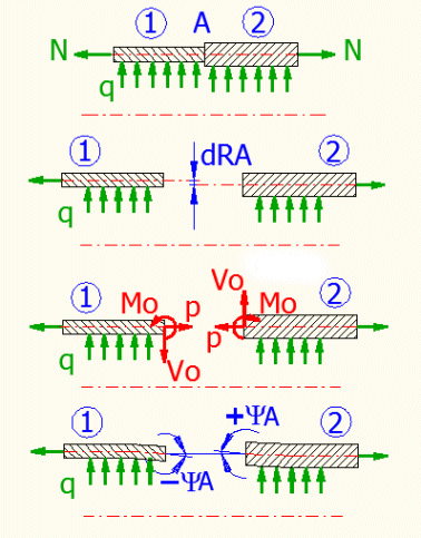
Process:
As the definition of the shells' release and definition of the boundary conditions can be demanding, solution of the most frequent cases has been prepared. The select list contains the type of the connected shells, their load and boundary conditions. A picture appears after the selection. By pressing the "OK" button, you open sections that are necessary for the solution. At the same time, the individual shells are released (the loading definition) and the boundary conditions are defined. This is solved by writing the corresponding formulas in the corresponding cells.
Release of the shells consists in writing the corresponding formulas in the input parameters of individual shells (see [10.1]). Pressing this button removes formulas from all input parameters and replaces them with a numerical value. This command can be used before you start defining the actual release of the shell and the actual boundary condition. You will thus ensure removing all potential unwanted definitions form previous calculations.
This value defines how many times in succession the Excel "Goal seek..." function is engaged.. The range of input values is 1-30. Usually, however, the solution converges very quickly (4-5 steps), so the pre-set value of 10 is sufficient. The percentage written in the dialogue specifies the process of the solution after starting the approximation.
The "Goal seek..." function used for approximation of the solution can find a satisfactory solution, but it terminates searching for the solution prematurely if the differences in results between the individual steps are low; the solution can be subject to an unnecessary error. This is why the sensitivity is increased for the pre-defined cases by multiplication of the results with this coefficient ("_Sensitivity"). Usually, this parameter need not be changed; its value is automatically set during the selection from [10.1].
After starting the approximation, values in these fields are subsequently
changed to reach the desired result in [10.8-10.13].
The individual parameters (cells) are named "_Variable1","_Variable2" and
"_Variable3". Link these variables to the input parameter that you want to
change in the corresponding section [6.0, 7.0, 8.0,
9.0]. For example, if you do not know the "Vo" force, which is necessary for
deformation of the shell, write the formula "=_Variable1" in a cell containing
the "Vo" value.
Pushing the "<=0" button clears the values.
Write an equation you want to solve in this cell (cells). After starting the approximation, the value of parameter [10.5] "_Variable1" is changed so that the result of the equation written on this line corresponds to the value entered on the following line. For example, you want the change of the cylindrical shell's radius to be zero. In this case, you can write for example "=_dRA_06" (or possibly "=_dRA_06*1000" for higher sensitivity) in this cell. Enter the desired result "0" in the following cell [10.9].
Enter the desired result of the equation from the previous line in this cell (cells). If you push the "Solve" button, this equation is solved with no regard to other equations. This can be convenient if you have wrongly set the conditions for releasing the shell and the solution does not converge.
You can use the individual calculations for mutual connection of various shells. In this case, it is necessary to release the individual components, define the boundary conditions and write the corresponding formulas (conditions) in the solver. The following text describes several frequent cases of shell structures.
This example of a connection simulates a connection between a pipe and a flange, which is a very frequently solved problem. You can also simulate a pipe with a rib, for example. Enter the dimensions of the shell [6.4, 6.5] and its load with overpressure "q" [6.6]. The axial load "p" [6.8] will be zero.
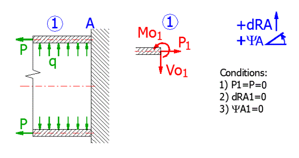
Release of the shell:
The shell will be loaded with a boundary force and a border moment.
Boundary conditions:
Enter the dimensions of the shell[6.4, 6.5], the overpressure stress "q"[6.6] will be zero, the axial load "p"[6.8] will be zero, the circumferential force "Vo"[6.9] will be a half (F/2).
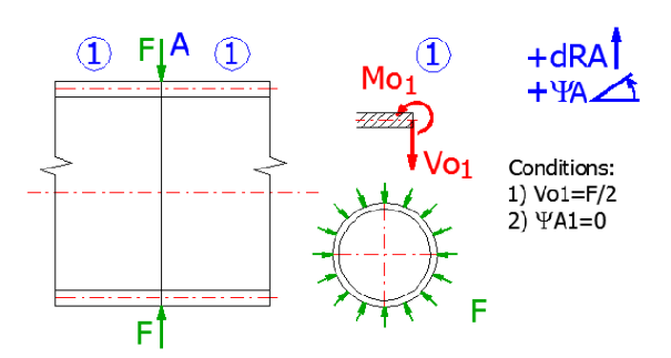
Release of the shell:
The shell must be divided into two parts in a place where the
circumferential force acts and its half must be solved. A half of the shell will
thus be loaded with a half of the original circumferential force and a zero
axial shift will be in the point of action.
Link the "Changed parameter 1" in the cell specifying the moment "No"
[6.9] so that it contains: "=_Variable1"
Boundary conditions:
Axial shift in the point A=0. The equation in the cell Equation 1
[10.8] will be: "=_Psi_06a*_Sensitivity". The desired Result1 in the cell
[10.9] equals 0.
Enter the dimensions of the cylindrical shell[6.4, 6.5] and dimensions of the
conical shell [8.4, 8.5, 8.6] (radius RA=R). Enter the
load with overpressure "q" [6.6, 8.7] and axial load
"p" [6.8].
The axial stress in the conical part will divide into a section parallel with
the surface and a radial force affecting the edge of the shell.
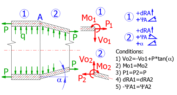
Release of the shells:
Release the individual shells and load their ends with a boundary force "Vo",
moment "Mo" and axial force "P" (for a conical shell, the boundary force Vo will
be increased by a radial component, which will be produced by distribution of
the force parallel with the surface of the cone.
Cylindrical shell:
Conical shell:
Boundary conditions:
Information on setting of calculation parameters and setting of the language can be found in the document "Setting calculations, change the language".
General information on how to modify and extend calculation workbooks is mentioned in the document "Workbook (calculation) modifications".
^