The calculation is designed for geometrical designs and complex examinations of shafts.
The programme solves the following tasks:
Simple definition of installed shafts, including hollow ones.
Options of definitions of necking-down, recesses, grooves and calculation of the relevant coefficients of stress concentration.
Simple definition of spatial shaft load.
Calculation of reactions, courses of forces, moments, stress, deflection and bending angle of the shaft and others.
Calculation of critical speed and safety coefficients.
Support of 2D and 3D CAD systems.
The calculation is based on data, procedures, algorithms and data from specialized literature and standards AGMA, ISO, DIN and BS. List of standards (DIN 743).
User interface.
Download.
Purchase, Price list.
Information on the syntax and control of the calculation can be found in the document "Control, structure and syntax of calculations".
Information on the purpose, use and control of the paragraph "Information on the project" can be found in the document "Information on the project".
In most cases, shafts are used to transfer rotary movements and torsion moments. They are usually supporting elements for toothed wheels, pulleys, clutches, etc. and are loaded with spatial bends, torsion moments and axial forces. A major part of shafts is shaped with recesses, necking-down, grooves and holes, which cause undesirable stress concentrations. The design should, therefore, include the following criteria, which should be checked in calculations:
It is advisable to follow the following procedure with the design and check.
In this paragraph you can make a preliminary design of the shaft diameter based on the transmitted power, speed and loading regime. Use this value then as a default (orientation) value when executing a design of the real shape of the shaft.
Select the desired system of calculation units from the list box. After switching over units, all input values will be converted immediately.
Enter the power which will be transmitted by the shaft.
Enter shaft speed.
The torsion moment is gained from the transmitted power and speed. This moment is decisive for the preliminary design of the diameter.
Use the designed min. diameter of the shaft as initial information for the design of the real shape and dimensions of the shaft, which will be checked in the following paragraphs.
Use one of the 3 options in the list box for the purposes of the preliminary design.
Use one of the 3 options (A - the lowest quality material, C - the best) for the purposes of the preliminary design.
Define the shape and location of supports (bearings) in this paragraph. You can define a shaft with a maximum of 10 cylindrical (conical) elements, which may be hollow. Define also the rounding radius for transitions between individual cylindrical elements. This radius affects calculations of stress in dynamic strength checks of the shaft. Enter dimensions of the shaft successively in the table [2.2] and observe the shape of the designed shaft in the picture.
The change-over switch defines whether the shaft is displayed over the whole area of the window (with optical deformation of the shaft), or whether the width and length is displayed in the same scale.
The table for definition of the shaft includes ten columns for a maximum of ten cylindrical (conical) elements of the shaft, and rows where you can enter dimensional parameters of the particular section of the shaft. Follow the schematic diagram.
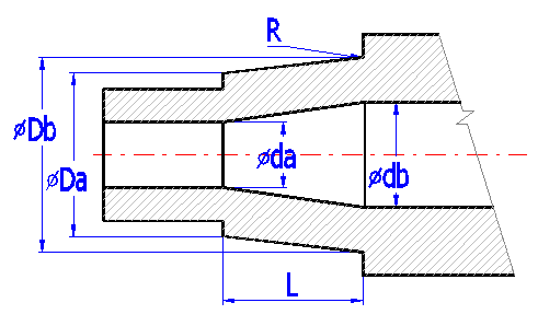
The items listed:
| Origin | Initial co-ordinates of the cylindrical part of the shaft from the left end of the shaft. |
| L | Length of the part of the shaft |
| Da | Outer diameter on the left |
| Db | Outer diameter on the right |
| da | Inner diameter on the left |
| db | Inner diameter on the right |
| R | Rounding between cylindrical section. (is defined for the right side of the section) see example |
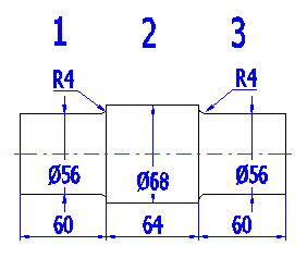
| 1 | 2 | 3 | |
| Start | 0 | 60 | 124 |
| L | 60 | 64 | 60 |
| Da | 56 | 68 | 56 |
| Db | 56 | 68 | 56 |
| da | 0 | 0 | 0 |
| db | 0 | 0 | 0 |
| R | 4 | 4 |
The parameter defines the total length of the shaft.
Use the change-over switch on the right to determine which support (bearing) is fixed and which is sliding. The setting affects calculations of stress in axial force. The position and type of support are displayed in the picture of the shaft as a red triangle.
The quality of the shaft surface substantially affects the fatigue strength, particularly with harder materials. Select the corresponding surface (method of machining) in the list box. The corresponding roughness Ra in units (micrometer/microinch) is in parenthesis.
In case of dynamic stress of the shaft or use of fragile materials, an undesirable concentration of stress occurs in points of shape changes of the shaft (necking-down, grooves, lubrication holes, rounding between sections, etc.). The highest stress can mostly be found right at these points. Therefore, in case of dynamic stress of the shafts we recommend including this effect in calculations and defining notches in this paragraph.
In this paragraph, the value of the ultimate tensile strength of material is used to specify Notch factor b. If the check mark button is enabled, a value according to the selected material of the shaft is used [6.2].
The notch sensitivity factor q is used for calculation of a notch
factor b using the coefficient of the
notch shape factor a according to the formula:
![]()
If the check mark button[3.1] is enabled, a notch sensitivity factor according to the selected material of the shaft is used [6.1].
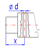
If the designed shaft includes a transverse hole(s), enter parameters in the table acc. to Fig. A. The position of the hole is marked using a red line in the schematic diagram.
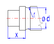
If the shaft is provided with one or more necked-down parts, enter their parameters in the table acc. to Fig. B. The necking-down is marked using a green rectangle in the schematic diagram.
Shafts usually include a series of other notches - potential concentrators of stress. Some common types (a groove for a key, grooved shaft and pressing on) are specified in the list box. Set the place and scope of effects according to Fig. C. A common notch is marked using a blue dimension in the schematic diagram.
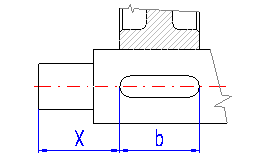
Select the type of pressed on connection according to the illustration.

The table includes notch coefficients b in places of rounding between individual parts of the shaft.
The following rules are applicable for definition of loading:
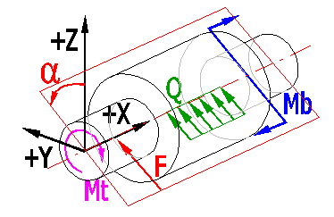
Loading in the "Definitional" plane
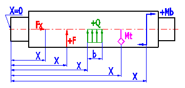
Enter maximum nominal values in the table of loading forces. Specify the dynamic character of loading forces in paragraph [6]. The meaning of the entered parameters is as follows:
| X | The point of action of the force measured from the beginning of the shaft (point 0) |
| Fx | Axial force (force acting in the shaft axis) |
| F | The force acting perpendicularly to the shaft axis (can be found in the "Definitional" plane) |
| alpha | The angle between the "Main" and "Definitional" planes (for force F) |
| Mt | Torsion moment. |
| Mb | The torsion moment (can be found in the "Definitional" plane) |
| alpha | The angle between the "Main" and "Definitional" planes (for moment Mb) |
| Q | Continuous load (can be found in the "Definitional" plane) |
| b | The length of the point of action of the continuous load |
| alpha |
For calculation of the critical speed of the shaft [7.13], it is necessary to define all material disks which are firmly connected to the shaft. You can enter the weight of the disk and its position on the shaft directly in the table or use an auxiliary calculation which specifies its weight using its width, outer and inner diameter.
If the shaft is oriented in the machine horizontally and the rotating masses affect the deflection of the shaft, set the change-over switch to "Yes". If the shaft is oriented vertically and the weight of rotating masses has no influence on the deflection of the shaft, set the change-over switch to ">No" (in this case, no additional axis loading of the shaft will be considered).
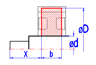
In the table you can define a maximum of 5 additional material disks firmly connected to the shaft. If the reversing switch is enabled at the end of the row, the calculation of the weight uses values defining dimensions of the disk. If the reversing switch is disabled, the weight entered in the last column and distributed continuously along the width "b" is used.
Meaning of columns:
| X | Co-ordinates of the left marginal point of the material disk measured from the origin |
| D | Outer diameter of the material disk |
| d | Inner diameter of the material disk |
| b | Width of the material disk |
| Ro | Specific mass of the disk material |
| m | Mass of the disk |
Enter material and the type of loading of the shaft in this paragraph. Material of the shaft can be chosen from the list of materials (strength values are derived from tensile strengths and the type of material), or your own strength and material values can be entered.
Select the type of material which will be used for production of the shaft from the list box. The range of ultimate tensile strength [MPa/psi] is given in parenthesis. Then in the list box on the right, select the desired ultimate strength or enter directly the value in row [6.2]. If the check mark button to the right of the tensile strength is enabled, other strength parameters are calculated using the tensile strength. These values are then added to the respective input fields. When selecting the type, other material values, particularly the specific mass and modulus of elasticity in tension and in shear are then added.
Material parameters are necessary for the following calculations:
| Parameter | Calculation |
| Yield points | Calculation of static coefficient of safety |
| Fatigue limits | Calculation of dynamic coefficient of safety |
| Specific mass | Bend stress, deflection, critical speed |
| Modulus of elasticity in tension | Deflection of the shaft |
| Modulus of elasticity in shear | Distortion of the shaft |
If the shaft is exposed to a bending stress due to dead load (horizontally positioned shaft), select the value "Yes".
Coefficients of safety are calculated along the length of the shaft. In case the coefficient of safety exceeds the preset value, the preset value is used. This allows users to enlarge (zooming) diagrams in the field of low safety, which is important when considering the design.
The coefficient of stress a0 is used for calculation of the equivalent (comparative) stress. The preset value is based on the type of dynamic loading of the shaft. If you wish to enter your own value, disable the check mark button.
The nominal loading is usually applied for the calculation. The coefficient of maximum loading covers the difference between the nominal and maximum loading. This coefficient can be entered for each particular type of loading.
The start-up torsion moment of the electric motor is 150% of the nominal one. 6.23 In this case, the coefficient of maximum loading for torsion [6.23] = 1.5.
Four list boxes allow users to define the type of loading which acts on the shaft. For simplification, the shaft can be designed for the following types of loading.
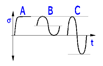
Loading by bending moment - Static
Loading by a shifting force -
Static
Loading by a torsional moment - Repeated
Loading by a tensile
force - Static
Loading by a bending moment - Reversed
Loading by a shifting force -
Reversed
Loading by a torsional moment - Repeated
Loading by a tensile
force - Static
When dynamically checking the shaft, it is possible to include the effects:
If the shaft is loaded dynamically (repeated cyclical loading or the number of cycles is over 1000), it is advisable to include all effects.
This paragraph gives basic results of calculations which show a compact review of strength and functional checks of the designed shaft. The left part gives minimum, maximum and selected values. The right part shows a universal diagram which allows users to display any calculated curve. The lower part of this paragraph shows a table in which you can display exact values of the selected curve at selected points on the shaft.
The level of reaction in the first and second support in direction X (shaft axis), Y,Z and total radial reaction (S y+z).
Maximum deflection is an important parameter when considering functionality of the shaft. Its maximum permitted value depends on the type of shaft, its function and structural features. The following recommendations can be applied for its size (shaft with toothed wheel):
At the point of seating of the toothed wheel
Or recommended maximum deflection (not at points of seating of wheels) is for:
Depends on the structure and type of loading. Recommended max. value j = 0.25° per one meter of length of the shaft (j = 0.075° per one foot of the length). In case of a smooth engagement, permanent torsional moment can be substantially higher.
The angular deflection of the shaft at points of seating of the toothed wheel should not exceed a value between 0.05° and 0.12° (3' - 7').
The angular deflection at bearing points depends on the type and inner structure of the bearing. Generally applicable:
| Max angular deflection [°] | Type of bearing |
| 0.1 | Single-row ball bearings |
| 3 | Double-row self-aligning ball bearings |
| 0.1 | Single-row roller bearings |
| 0.03 | Other roller bearings |
| 1.5 | Spherical roller bearings |
| 0.03 | Single-row tapered roller bearings |
| 2 | Thrust spherical roller bearings |
| 0.05 | Sliding bearings (b/d < 1) |
These are the maximum values of individual stress components. However, the safety coefficient should be decisive for the design.
1.2 to 2.2 - Sufficiently plastic materials.
2.0 to 3.0 - Forgings, fragile materials (highly alloyed steels, very strong cast irons)
2.5 to 3.5 - Castings, fragile materials (highly alloyed steels, very strong cast irons)
For the calculation, it is important to include all rotating masses firmly connected to the shaft [5]. Critical speed is calculated using Rayleigh's method (bending oscillation).
The speed of the shaft should be:
lower than 0.8 * Critical speed - subcritical operation
higher than 1.25 * Critical speed - above critical operation
If the shaft is operated in the field of above critical speed, it is necessary to go over the field of critical speed quickly both with the running up (excess of power) and running out (sometimes braking is necessary) as well.
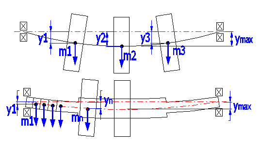
Applied formulas:
Critical speed.
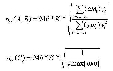
with:
mi = i-th rotating mass located on the shaft
yi = static deflection under i-th weight located on the shaft
g = gravitation constant
K = coefficient of shaft bearing (as apart from stiffness and deflection of the
shaft, critical speed depends on the bearing, the following coefficient can be
applied in practice)
The calculation gives three results:
In the list boxes, select the parameters in which you are interested and for which you wish to know exact values at certain points of the shaft. You can find out the values of up to eight check points. Enter their co-ordinates in row [7.16].
In the list boxes, set the parameters of the graphs you wish to be displayed. Fast scrolling through of all graphs is possible using the scroll button. The axis of the blue curve is positioned on the left and the axis of the green curve on the right.
Paragraphs 8 to 12 include graphs of the selected values. Paragraphs 8,9 and 10 allow users to switch values in the plane XZ and the plane XY, the summary of values and the angle between the plane XZ and the vector of the resulting value (summary XZ and XY) on and off. Switch the graph on/off by enabling/disabling the check mark button.
Information on options of 2D and 3D graphic outputs and information on cooperation with 2D and 3D CAD systems can be found in the document "Graphic output, CAD systems".
Information on setting of calculation parameters and setting of the language can be found in the document "Setting calculations, change the language".
Standard procedures and formulas are used for calculation of deformations and stress.
As literature gives many theories and procedures in the field of calculation of notch effects and coefficients of safety, only the basic formulas used in the calculations are mentioned here.
![]()
de - Bending stress.
dg - Tensile (compressive) stress.
tt - Torsional stress.
ts - Stress in shear.
a0 - Coefficient of loading - based on the type of dynamic loading of the shaft.

Bending static safety

de - Bending stress
KmaxL - Coefficient of maximum loading - see [6.20]
Reb - Bending yield point
Similarly then for partial safety in tension SFg, torsion SFt and shear SFs

Bending dynamic safety

Medium bending stress

Amplitude of bending stress

Rebc - Bending fatigue limit (with reversed or repeated loading).
dmax - Maximum bending stress in loading cycle.
dmin - Lowest bending stress in loading cycle.
Total bending shape coefficient

Bending notch factor
![]()
ye - Coefficient showing sensitivity of material to asymmetry of the cycle.
ue - Coefficient of the part size.
ep - Coefficient of surface quality.
ab - Notch
shape factor.
q - Notch sensitivity factor.
Similarly then for partial dynamic safety in tension SFgd, torsion SFtd and shear SFsd
General information on how to modify and extend calculation workbooks is mentioned in the document "Workbook (calculation) modifications".
The calculation itself is executed in the VBA module, therefore it is not available to the user. In the sheet "Tables", however, it is possible to modify material coefficients, notch factors, surface coefficients and size coefficients.
^