The calculation is intended for geometrical design and strength check of force couplings of shafts with hubs with a cylindrical contact area. The application provides solutions for the following tasks:
The calculation is based on data, procedures and algorithms from specialized
literature and standards ANSI, ISO, DIN and others.
List of standards: ANSI B4.1, ISO 286
User interface.
Download.
Purchase, Price list.
Information on the syntax and control of the calculation can be found in the document "Control, structure and syntax of calculations".
Information on the purpose, use and control of the paragraph "Information on the project" can be found in the document "Information on the project".
The workbook with calculation of force couplings of shafts and hubs can be divided into two ranges. A range of common input data and results (paragraphs [1, 9]) and a range of individual calculations (chapters A, B) relevant for the given type of coupling only. Two types of tasks can then be solved using the calculation:
When choosing a suitable type of coupling there must also be taken into account, besides the dimensional parameters of the coupling, its use value, time demands and financial costs of production, installation and operation of the coupling. The comparative document "Choices of type of coupling of a shaft with a hub" can be helpful in selecting a suitable type of coupling.
Typical calculation / design of a coupling includes of the following steps:
In this paragraph, enter basic input parameters, characterizing the manner, conditions and amount of loading, design of the coupling and materials of the shaft and hub.
In the selection list, choose the desired calculation unit system. All values will be recalculated immediately after switching to other units.
Enter the power which will be transferred by the shaft.
Enter the shaft speed.
The transferred power and speed provide a torsional moment, which is the
basic input value for the design of the coupling.
Set the maximum axial force straining the coupling.
Select the type of drive which best meets the requirements of the entered
specifications.
Select the loading conditions which best meet the requirements of the entered
specifications.
Choose whether the coupling will be loaded during operation in one direction of rotation or the direction of rotation of the shaft will be changed.
Choose the total number of machine start-ups during the desired service life of the coupling.
In case you use a hollow shaft in the coupling, enter here the inner diameter of the shaft. This parameter affects the size of loading of the shaft in torsion and considerably affects determination of the minimum permitted diameter of the shaft [1.15].
With regards to accuracy and credibility of input information, importance of the coupling, quality of production and accuracy of the calculation, it is usually chosen in a range from 1.5 to 3.
Use the designed minimum diameter of
the shaft as initial information for the design of the coupling.
From the list box, select the type of material that the shaft will be manufactured of. The value in brackets states the range of tensile strength [MPa/ksi]. In the right-hand list box, select the desired ultimate tensile strength. If the check box to the right of the list box is checked, the required tensile parameters are set automatically for the selected material. Otherwise, complete the material characteristics manually. Allowable stress in shear [1.20] is used for the strength check of the shaft for torsion. The permissible pressure value [1.21] is used for checking contact areas for deformations, and it is determined for the selected material with respect to loading conditions and operational parameters of the coupling.
From the list box, select the type of material that the hub will be manufactured of. The value in brackets states the range of tensile strength [MPa/ksi]. In the right-hand list box, select the desired ultimate tensile strength. If the check box to the right of the list box is checked, the required tensile parameters are set automatically for the selected material. Otherwise, complete the material characteristics manually. The permissible pressure value [1.29] is used for checking contact areas for deformations, and it is determined for the selected material with respect to loading conditions and operational parameters of the coupling.
Interference fits are rigid (fixed) fits based on the principle of constant elastic pre-stressing of connected parts using interference in their contact area. Outer loading is transferred by friction between the shaft and hub created in the fit during assembly. The friction is caused by inner normal forces created as a result of elastic deformations of connected parts.
Interference fits are suitable for transfer of both large torques and axial forces in rarely disassembled couplings of shaft and hub. These fits enable high reliability of transfer of even high loads, including alternating loads or loads with impacts. They are typically used for fastening geared wheels, pulleys, bearings, flywheels, turbine rotors and electromotors onto their shafts, with gear rings pressed onto wheel bodies, arms and journals pressed onto crankshafts.
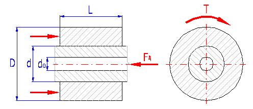
Press on in general means inserting a shaft of larger diameter into a hub opening which is smaller. After the parts have been connected (pressed-on), the shaft diameter decreases and the hub opening increases, in the process of which both parts settle on the common diameter. Pressure in the contact area is then evenly distributed. Interference d, given by the difference between assembly shaft diameter and hub opening diameter, is a characteristic feature and a basic quantity of interference fit. The value of contact pressure, as well as loading capacity and strength of the fit, depends on the interference size.

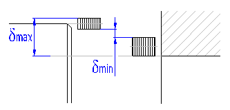
With respect to the fact that it is not practically possible to manufacture contact area diameters of connected parts with absolute accuracy, the manufacturing (assembly) interference is a vague and accidental value. Its size is defined by two tabular values of marginal interferences which are given by the selected fit (by allowed manufacturing tolerances of connected parts). Interference fits are then designed and checked on the basis of these marginal assembly interferences. Minimum assembly interference dmin is a basic value for solving the loading capacity of a coupling; maximum interference dmax is decisive for its strength check.
Advantages of the coupling:
Disadvantages of the coupling:
The main imperfection of interference fits are increased demands on coupling assembly and considerable problems connected with potential coupling disassembly. Therefore, these couplings are used in practice namely for non-detachable couplings of shafts and hubs. The press process varies technologically in two basic ways:
Although interference fits may theoretically be disassembled, the forcible disassembly of couplings with large interference usually results in damage to contact areas and sometimes even in destruction of parts. After re-assembly, the original loading capacity of the coupling is not achieved (the clamping force of the coupling decreases by approx. 15 to 20%). Damage to contact areas may be reduced by their surface hardening. Only "shrink fit" couplings with smaller interference can usually be disassembled and reassembled with satisfactory results. Hydraulic assembly (disassembly) of the coupling may sometimes ensure the requirement of detachability. In case of this assembly method, the surfaces of connected parts are pushed away by high-pressure oil forced into the pressure joint using specially adjusted grooves and channels. The oil pressure is 1.5 - 2 times higher than the coupling contact pressure.
The use of interference fits is also less advantageous for smaller shaft diameters. With respect to the relative "roughness" of used fit systems, the value of relative interference d/d increases sharply in the zone of small diameters. This results in disproportionately high contact pressure (with respect to the requirements on loading capacity of the coupling) and therefore, high tension due to press-on. From the coupling strength check point of view, there arises the requirement to use materials of higher quality or to maintain higher accuracy level in parts production.
This paragraph can be used to choose the parameter of the given type of coupling and to design dimensions of the coupling.
Although there can be generally coupled parts without any tolerance zones, only two methods of coupling of holes and shafts are recommended due to constructional, technological and economic reasons.

where:
d=D ... basic size
//// ... hole tolerance zone
\\\\ ... shaft tolerance zone
The option of the system for the specified type of product or production is always influenced by the following factors:
There two basic ways of solving assembly process in case of interference fits:
Degreasing of the contact area surface causes an increase in friction coefficient and thus an increase in coupling loading capacity. However, in case of couplings with longitudinal press (force fit) it also leads to an increase in required press force.
Galvanic plating of contact areas leads to a significant increase in the friction coefficient and thus to an increase in the coupling loading capacity.
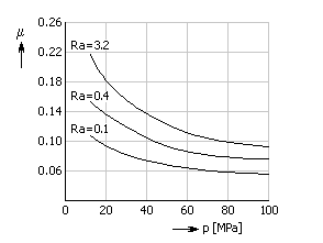
Friction coefficient significantly influences the loading capacity of the whole coupling. The loading capacity increases with its increasing value. The friction coefficient value depends on the material of connected parts, the roughness and purity of surfaces, contact pressure value and method of press.
|
Hub material |
Longitudinal press | Transverse press | ||
| Dry | Greased | Dry | Greased | |
| Steel | 0.07 ... 0.16 | 0.05 ... 0.12 | 0.15 ... 0.25 | 0.08 ... 0.16 |
| Cast iron | 0.09 ... 0.15 | 0.04 ... 0.08 | 0.10 ... 0.16 | 0.08 ... 0.12 |
| Al alloys | 0.05 ... 0.09 | 0.04 ... 0.06 | 0.10 ... 0.15 | - |
| Bronze | 0.06 ... 0.08 | 0.03 ... 0.05 | - | - |
| Brass | - | - | 0.17 ... 0.25 | - |
Use higher values for small contact pressures and surfaces with higher roughness. The following diagram shows the influence of connected part roughness and contact pressure value on the friction coefficient for a steel hub:
Friction coefficient may be significantly increased by galvanic plating of contact areas. The mutual diffusion of atoms of both layers leads to surface "jointing" and the friction coefficient expresses rather the resistance to contact area shear.
| Type of coating | Longitudinal press | Transverse press |
| Soft coatings (Cd, Cu, Zn) | 0.45 ... 0.55 | 0.65 ... 0.80 |
| Hard coatings (Cr, Ni) | 0.70 ... 0.85 | 0.65 ... 0.80 |
Safety against gliding shows the rate between the minimum theoretical loading capacity (friction force) of the coupling and total service loading. With respect to the accuracy and value of input information, type and importance of coupling, production quality and calculation accuracy, its value is usually selected from 1.2 to 2.
Expresses the rate between allowable stress in the tension of coupling materials and maximum comparative stress in the hub, possibly the shaft (see [3.7, 3.13]). With regards to accuracy and credibility of input information, importance of the coupling, quality of production and accuracy of the calculation, it is usually chosen in a range from 1.2 to 2.5.
This coefficient gives the total effects of operational parameters on decrease of loading capacity of the coupling. Its size depends on the type of drive and loading, operational conditions and service lifespan of the coupling. With regards to the mentioned parameters, the literature gives values of the coefficient in a range from 1 to 3.
This paragraph serves for the preliminary design of coupling dimensions. After pressing the button, the program designs suitable coupling dimensions for the selected fits (see [2.24]). The calculation itself designs the coupling with the smallest dimensions possible, observing the recommended rates of length and diameter of the hub with respect to the designed shaft diameter. After the calculation, the designed solution is sequenced in the table.
If the design calculation was unsuccessful and no suitable solution was found, this fact is indicated by a warning message and the table of solutions is deleted. In such cases, repeat the design for a coupling with materials of a higher quality.
This paragraph can be used to determine dimensions of the coupling. The dimensions can be chosen manually or the values of the designed solution can be transferred using a selection from table [2.13].
When selecting coupling dimensions, bear in mind some basic facts:
|
Hub material |
L/d | D/d |
| Steel | 0.6 ... 1.2 | 2 ... 2.4 |
| Cast iron, light alloys | 1.2 ... 1.5 | 2.2 ... 2.6 |
This parameter gives the minimum diameter of shaft, which is necessary for safe transfer of the entered torsional moment.
Select a shaft diameter greater than the minimum recommended diameter dmin. The loading capacity of the coupling increases and the stress decreases in the connected parts with increasing shaft diameter. In case of couplings with hollow shafts, it is also necessary to consider the influence of the shaft wall thickness on stress in the hub. (see [2.14]).
The parameter gives the outer diameter of the full part of the hub. Increase in the hub results in decrease in its stressing, with simultaneous slight increase in the coupling loading capacity.
The contact area roughness depends on the shaft size, the method of treatment of parts and the level of accuracy of the selected fit. With increasing contact area roughness, the friction coefficient as well as coupling loading capacity increase. On the other hand, the mounting smoothness of the surface (longitudinal press) and possibly the size of subsidence (transverse press) also increase. This decreases effective coupling interference (see [2.30]).
|
Shaft diameter |
Contact area roughness [mm (min)] |
||
| [mm] | [in] | Shaft | Hub |
| up to 10 | up to 0.5 | 0.2 (8) | 0.4 (16) |
| 10 - 50 | 0.5 - 2 | 0.4 (16) | 0.8 (32) |
| 50 - 120 | 2 - 5 | 0.8 (32) | 1.6 (63) |
| 120 - 250 | 5 - 10 | 1.6 (63) | 1.6 (63) |
| 250 - 500 | 10 - 20 | 1.6 (63) | 3.2 (125) |
| 500 - 1000 | 20 - 40 | 3.2 (125) | 6.3 (250) |
| 1000 - 2500 | 40 - 100 | 6.3 (250) | 12.5 (500) |
| over 2500 | over 100 | 12.5 (500) | 25 (1000) |
Set the actual functional coupling length (without rounding, possibly bevelling of edges). The loading capacity of the coupling increases with increasing length. The coupling length has no direct influence on load distribution in the connected parts.
This paragraph is intended for the design of the fit. When selecting the fit, you specify the size of assembly interferences of connected parts as well as the loading capacity and strength of the coupling. The correct selection of the appropriate fit is therefore the basic requirement when designing interference fits.
Each fit is characterized by proper manufacturing tolerances of the shaft and hub [2.25 - 2.28]. The combination of limit deviations of work measures simultaneously specifies the limit interference values that can occur during assembly. These limit interferences then become the basis of the coupling solution. The minimum interference [2.32] is decisive for solving the coupling loading capacity, the maximum interference [2.34] is decisive for strength checks.
To achieve the desired safeties [2.7, 2.8] select the fit of the designed coupling so that:
The diagram in the figure in paragraph [2.29] shows the parameters of designed fit.
A suitable fit can be selected in three ways:
The effort to achieve the most effective coupling design leads to the requirement for the smallest difference possible between its limit interferences when selecting the fit. Existing relatively rough fit systems, however, enable this only when selecting higher levels of accuracy, i.e. at higher production costs. In lot production this problem can sometimes be solved by selective assembly based in previous categorization of parts into subgroups according to the interference.
You can run the automatic design of the fit using the button on line [2.23]. After the design has been run, the calculation will go through all recommended (preferred) fits and will try to select a suitable solution. If none of the recommended fits are suitable, the calculation will design the limit deviations of connected parts directly. The deviations are selected according to the normalized line of tolerances ISO 286, possibly ANSI B4.1. The appropriate tolerances are designed as large as possible to maintain the rule of the same or higher level of accuracy in case of shaft tolerance.
If the calculation has not found a suitable solution, use one of the following procedures to increase the loading capacity, possibly strength of the coupling:
Select the recommended fit from the list box. The cue for selection of the appropriate fit can be found in the graphical representation of interferences of individual fits shown in the figure in paragraph [2.35]. The list of recommended fits is compiled on the basis of the set system of calculation units [1.1] and selected system of fits [2.2].
The recommended fits are specified according to the ISO 286 international fit system for the calculation in SI units. The preferred fits are marked with a "*" in the list.
For calculation in Imperial units, the list includes preferred fits according to ANSI B4.1.
To increase transparency and legibility of the calculation, the parameters of the selected fit are presented in this paragraph graphically.
On the left, there is a schematic picture of limit deviations of shaft and hub related to the zero line (basic diameter) of the coupling.
The blue rectangle on the right represents the range of assembly interferences for the selected fit. To achieve the desired safeties [2.7, 2.8], select the fit of the designed coupling so that the whole rectangle lies between the lines of limit deviations.
Longitudinal press (force fit)
When using pressure, surface unevenness of connected parts is partially stripped
and smoothed. This results in reduction of the original assembly interference
and thus reduction of the coupling loading capacity. The resulting effective
coupling interference may then be significantly lower (especially in case of
smaller diameters). The amount of mounting smoothness of the surface depends on
the roughness of the connected parts.
Transverse press (shrink fit)
After balancing of assembly temperatures, there occurs plastic deformation of
surface micro-unevenness in the coupling. Such coupling subsidence causes a
reduction in original assembly interference and therefore, a reduction in
loading capacity of the coupling. This reduction in loading capacity is
significantly lower than in case of longitudinal press. The value of coupling
subsidence depends on the roughness of the connected areas.
This parameter specifies the minimum required assembly interference of the fit when the coupling still has not achieved the required loading capacity.
Minimum fit interference is characterized by the difference between lower shaft deviation and upper hub deviation (ei - ES) and is the decisive value in judging the coupling loading capacity.
This parameter sets the limit value of assembly interference when the coupling still complies with all strength checks with the desired safety [2.8].
Maximum fit interference is set by the difference between the upper shaft deviation and lower hub deviation (es - EI) and is the decisive value for strength checks of stress on connected parts.
This paragraph is intended to ease the selection of suitable fit in line [2.24]. The assembly parameters of all recommended (preferred) fits are shown here in graphical form.
Blue columns show the range of assembly interferences for the specific fit. You can judge the suitability of individual fits on the basis of the mutual position of the appropriate column with lines of limit interferences. To obtain the desired safeties [2.7, 2.8] of the designed coupling, the whole column must lie between these limit lines.
In this paragraph, the check of loading capacity of the coupling and all necessary strength checks are performed.
With respect to a significant variance of values of the assembly interference for the selected fit, the checks are performed for the medium interference dc and for both limit interference values dmin, dmax. Although in practice interferences near the mean value should occur most commonly, it is also necessary to provide sufficient strength and loading capacity of the coupling for less probable limit interferences. For the check of loading capacity of the coupling, the minimum interference is decisive, for strength checks the maximum interference is decisive.
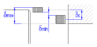
Securing the transfer of the whole outer loading solely by friction between the connected parts is the basic requirement of interference fit loading capacity. The coupling loading capacity is then checked by comparing the frictional force [3.5] with its total service loading [2.12].
The frictional forces in the coupling are formed due to contact area interference; the lowest loading capacity will therefore be shown with couplings with minimum assembly interference. If the designed coupling is to accommodate this in full, safety against gliding must be greater than the required safety [2.7] even in case of less probable minimum interference.
During assembly of the coupling, plastic deformation of surface micro-unevenness in contact areas (see [2.30]) occurs. This results in a reduction in assembly interference of the fit. This parameter then specifies the actual effective interference of the fit securing the coupling loading capacity.
Press-on results in creating the biaxial state of stress in the hub, defined by the radial sr and tangential st part of stress. The value of the stress increases with increasing assembly interference. The figure shows the distribution of both parts of the load in dependence on the hub diameter.
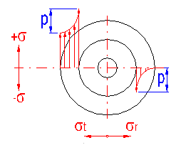
Strength check of the hub is performed by comparison of maximum comparative stress with allowable stress in tension. The comparative stress is set from partial components of stress on the basis of Mises hypothesis of specific energy from the relation:
![]()
Allowable stress is set by the yield strength for steel hubs; the allowable stress for hubs made of cast iron is determined as half the value of ultimate tensile strength.
If the designed coupling is to fully accommodate this, the resulting safety [3.12] must be higher than the desired safety [2.8] even in case of less probable maximum interference.
Press-on results in creating the biaxial state of stress in the shaft, defined by the radial sr and tangential st part of stress. The value of the stress increases with increasing assembly interference. The figure shows the distribution of both parts of the load in dependence on the shaft diameter. In case of full shafts, the stress is constant throughout the diameter.
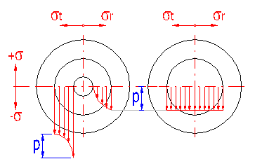
Strength check of the shaft is performed by comparison of maximum comparative stress with allowable stress in tension. The allowable stress is given by the yield strength of the shaft material. The comparative stress is set from partial components of stress on the basis of Mises hypothesis of specific energy from the relation:
![]()
If the designed coupling is to fully accommodate this, the resulting safety [3.18] must be higher than the desired safety [2.8] even in case of less probable maximum interference.
If the permissible pressure is exceeded, plastic deformation of the thin layer of contact areas may occur. This results in a reduction in contact pressure and subsequent reduction in the coupling loading capacity. As this phenomenon usually occurs only in case of couplings with maximum assembly interference (over-designed from the loading capacity point of view), the possible reduction in contact pressure has no significant importance in the total coupling loading capacity.
Check of coupling for deformation has only an informative meaning in case of interference fits. If the designed coupling accommodates this in all other checks, the possible exceeding of permissible pressure may not mean a threat to coupling loading capacity or strength. This check should also be complied with if possible especially in case of reassembled couplings.
The resulting safety of the coupling [3.26] is given by the ratio of the permitted shear stress of the shaft material to the calculated comparative stress. If the coupling is to be sufficient, the calculated safety must be higher than the required one [1.14].
In this paragraph, the mounting parameters are calculated for the designed coupling. In the left part of the paragraph, the parameters are specified for shrink fit couplings, in the right part for force fit couplings. The mounting parameters are relevant only for the type of coupling currently set on line [2.3].
Transverse press is done by non-forcible connecting of parts after previous hub heating (dilatation), or after previous shaft cooling (restriction). This paragraph enables specification of both necessary hub-heating temperature [3.35] and necessary shaft-cooling temperature [3.38] for the designed coupling.
The selection of heating or cooling depends on dimensions of the parts and technical possibilities. During hub heating, it is necessary to observe that the temperature when structural changes in material occur (in case of steels, approx. 200 to 400°C) is not exceeded. Heating of outer parts is usually done in an oil bath (up to 150°C) or gas or electric furnace. Parts with small diameter have to be heated to a much higher temperature than large ones. Cooling of shafts is usually done rather with smaller couplings, using carbon dioxide (-70 °C) or condensed air (-190 °C). For couplings with large assembly interferences, a combination of both methods may be used.
Shrink fitting is unsuitable for parts made of heat-treated steels and in case a heated part is fitted on a hardened one. In such cases it is necessary to cool the inner part or force fit the coupling.
For proper assessment of necessary mounting temperatures, the fit with maximum interference when mounting temperatures will also achieve their maximum is decisive.
Assembly clearance is used to secure easy insertion of a shaft into a hub without mutual damage of contact areas. Assembly clearance amounting to one thousandth of the shaft diameter is usually considered sufficient.
Heat expansion coefficient does not have a constant value in case of metal materials, but its size decreases with increasing temperature. If the required shrinkage is to be achieved during shaft cooling, it is necessary to use an adjusted value of heat expansion coefficient valid for the area of low temperatures when calculating the mounting temperature.
Longitudinal press is based on forcible pushing of a shaft into a hub under pressure or using mechanical or hydraulic jigs in case of smaller parts. The intensity of press force increases linearly in the press process (see figure). The force needed to release the coupling is approx. 20 to 25 % higher; it decreases linearly during shaft forcing.
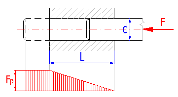
The press speed should not exceed 2 mm/s. To prevent seizing, steel parts are usually greased. It is also necessary to grease contact areas in case of large couplings with large interference, where extremely high press forces are required. Parts from different materials may be dry-pressed. Greasing contact areas enables the press process, however, on the other hand it leads to a decrease in friction coefficient and coupling loading capacity.
In order to judge the desired press force properly, the fit with maximum interference when the required press force is the largest is decisive.
The size of the pressing force is determined based on the "operational" friction coefficient, listed on line [2.6]. If the boundaries are to be greased during pressing, it is necessary to take account of the size of the friction coefficient.
This paragraph specifies an additional check of the coupling strained by additional load by radial force or bending moment.
The additional load causes redistribution of originally even contact pressure in the coupling. Check of the coupling then includes examination of new pressure conditions, determining the values of extreme pressure and their comparison with the permissible pressure. The pressure distribution under load of radial force and bending moment is shown in the picture.
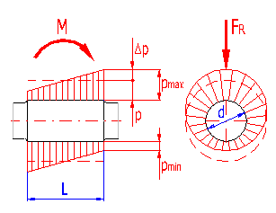
The value of maximum permissible pressure is determined on the basis of strength checks specified in paragraphs [3.7, 3.13]. The check of minimum pressure observes the danger of local diversion of contact areas and the creation of micro-shifts.
The calculation used for design and check of the coupling in paragraphs [2, 3] is based on the prerequisite that the coupling operates at temperatures close to the basic temperature 20°C (68°F) at which both material characteristics and coupling dimensions were determined. If the coupling works constantly at higher operational temperatures, its characteristics change significantly. The influence of temperature is proved in several basic facts:
This paragraph is used to examine and check the parameters of a designed interference fit working at a specific operational temperature.
Physical and strength properties of material change according to changes in temperature. This paragraph is intended to set the necessary properties of the shaft and hub material valid for the selected operational temperature. The properties of material at temperature 20°C (68°F) are specified in green fields.
Allowable stress in tension is given by yield strength in case of malleable materials; in case of brittle materials (cast iron), it is determined as half the ultimate tensile strength.
Unlike the main calculation, when only recommended fits are used during the designing of the coupling, this paragraph enables the selection of a random fit defined by the ISO 286 standard.
The selection of proper fit can be made in two ways:
- the selected fits are in the system of uniform hole, possibly uniform shaft
according to setup [2.2]
- hub and shaft tolerance zones prescribed for common use are used in the
selection
- hub tolerance equals or is greater than shaft tolerance
- tolerance of hub and tolerance of shaft do not differ by more than two degrees
- fits with a lower degree of accuracy are preferred
Transfer the parameters of the selected fit into the main calculation using the button in line [6.10].
Clamping connections are rigid (fixed) couplings based on the principle of clamping the connected parts in their contact area using outer elements. Outer loading is transferred by friction between the shaft and hub created in the fit during assembly. Friction in the clamping is caused by normal outer forces deduced using stressed bolt connections.
Clamping connections are suitable for the transfer of small and medium loads in case of frequently dismounted couplings. Typically, they are used for clamping clutches of shafts, connection of arms and shafts, in fixation of various adjustable collars and adjustable stops.
Clamping connections are manufactured in two basic types:
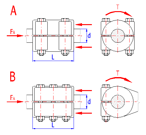
Advantages of the coupling:
Disadvantages of the coupling:
Temporary fits with low clearance H8/j7, H8/k7, H7/j6, H7/k6 or fits with mild interference H8/n7, H8/p7, H7/m6, H7/n6, H7/p6 are usually used for clamping connections.
This paragraph can be used to choose the parameter of the given type of coupling and to design dimensions of the coupling.
Select the desired hub design from the list box.
Degreasing of the contact area surface causes an increase in friction coefficient and thus an increase in coupling loading capacity.
Friction coefficient significantly influences the loading capacity of the whole coupling. The loading capacity increases with its increasing value. The value of friction coefficient depends on the material of connected parts, surface roughness and purity, method of contact pressure distribution and intensity.
| Hub material | Contact areas | |
| Dry | Greased | |
| Steel | 0.08 ... 0.18 | 0.05 ... 0.12 |
| Cast iron | 0.12 ... 0.20 | 0.04 ... 0.10 |
| Al alloys | 0.05 ... 0.10 | 0.03 ... 0.07 |
| Bronze | 0.06 ... 0.16 | 0.02 ... 0.08 |
| Brass | 0.04 ... 0.14 | 0.02 ... 0.05 |
Use higher values for small contact pressures and surfaces with higher roughness.
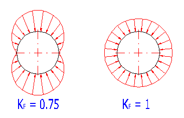
Specifies the influence of uneven distribution of contact pressure on the shaft circumference on the coupling loading capability and strength.
Clearance in fit and transverse flexural rigidity of sleeves is decisive for pressure distribution in the contact area. The smaller the clearance and the more flexible the sleeve, the more the pressure distribution approximates even distribution. With respect to expected pressure rates in the coupling, the coefficient value is set between 0.7 and 1. Cosine pressure distribution (see the picture) is usually considered relatively close to reality.
Safety against gliding shows the rate between the minimum theoretical loading capacity (friction force) of the coupling and total service loading. With respect to the accuracy and value of input information, type and importance of coupling, production quality and calculation accuracy, its value is usually selected from 1.3 to 2.5.
It is used for the check of coupling for deformation (see [8.13]) and states the rate between allowable and maximum contact pressures. With regards to accuracy and credibility of input information, importance of the coupling, quality of production and accuracy of the calculation, it is usually chosen in a range from 1.5 to 3.
This coefficient gives the total effects of operational parameters on decrease of loading capacity of the coupling. Its size depends on the type of drive and loading, operational conditions and service lifespan of the coupling. With regards to the mentioned parameters, the literature gives values of the coefficient in a range from 1 to 3.
This paragraph can be used to design dimensions of the coupling. When designing the coupling, first choose the desired diameter of the shaft [7.15]. For the set diameter, the program calculates the minimum functional coupling length [7.16] needed to secure safe transfer of service loading. Finish the design of coupling diameters by selecting the actual coupling length in line [7.17].
Recommended dimensions of hubs can be found in the document "Guiding values for choices of dimensions of hubs".
This parameter gives the minimum diameter of shaft, which is necessary for safe transfer of the entered torsional moment.
Select a shaft diameter greater than the minimum recommended diameter dmin.
The parameter gives the min. functional coupling length needed for safe transfer of service loading.
Select a coupling length greater than the calculated minimum length [7.16].
|
Hub material |
L/d |
| Steel | 1.0 ... 1.5 |
| Cast iron, light alloys | 1.6 ... 2.0 |
This paragraph is used for the connecting bolt design and determination of their mounting prestressing. In the design process, first choose the total number of connecting bolts [7.20]. The program will then calculate the allowable range of mounting pre-stressing for the specified coupling dimensions [7.21], securing the desired loading capacity and strength of the coupling. After the mounting prestressing [7.22] and bolt material [7.23] have been selected, the calculation will execute preliminary design of connecting bolt dimensions [7.24]. If the recommended thread is too big, repeat the design with material of better quality or a larger number of connecting bolts.
Select the value of mounting prestressing in connecting bolts in the range of values recommended in line [7.21].
A simplified calculation valid for prismatic bolts is used for the recommended thread size design, with the value of friction coefficient in threads equal to 0.15. Although this value is relatively accurate, we recommend using a specialized calculation in case of final calculations for the connecting bolt design.
In this paragraph, the check of loading capacity of the coupling and all necessary strength checks are performed.
Securing the transfer of the whole outer loading solely by friction between the connected parts is the basic requirement of coupling loading capacity. The coupling loading capacity is then checked by comparing the frictional force [8.4] with its total service loading [8.5].
If the designed coupling is to accommodate this, safety against glide must be higher than the desired safety [7.6].
A simplified calculation valid for prismatic bolts is used for the connecting bolt check, with the value of friction coefficients in threads and below the bolt head equal to 0.15. Therefore, consider the herein stated results as only orientation and approximate.
Check for deformation is done by comparing allowable pressure of lower quality material [8.14] with the calculated maximum contact pressure [8.15]. If the coupling is to accommodate this, the calculated safety must be higher than the desired safety [7.7].
The resulting safety of the coupling [8.20] is given by the ratio of the permitted shear stress of the shaft material to the calculated comparative stress. If the coupling is to be sufficient, the calculated safety must be higher than the required one [1.14].
The check is done by comparing allowable stress in tension of the shaft material [8.22] with calculated comparative stress affecting the inside shaft diameter [8.23]. If the coupling is to accommodate this, the calculated safety must be higher than the desired safety [7.7].
This paragraph can be used for a fast comparison of designed solutions of couplings of shafts with hubs. Only basic dimensions are given here for individual types of couplings. Complete dimensions of the coupling can be found in the independent chapter (section) of the respective calculation.
Information on setting of calculation parameters and setting of the language can be found in the document "Setting calculations, change the language".
General information on how to modify and extend calculation workbooks is mentioned in the document "Workbook (calculation) modifications".
^