The calculation is designed for geometric designs and strength checks of shaped couplings of shafts with hubs. The application provides solutions for the following tasks:
Design of a coupling with parallel side keys.
Design of a coupling with straight-sided splines.
Design of a coupling with involute splines.
Strength check of designed couplings.
The application includes a table of keys and splines according to ISO, SAE, DIN, BS, JIS and CSN.
Support for 2D CAD systems.
The calculation is based on data, procedures and algorithms from specialized
literature and standards ANSI, ISO, DIN and others.
List of standards: ANSI B17.1, ANSI B17.2, ANSI B92.1, ANSI B92.2M, ISO R773,
ISO 14, ISO 4156, DIN 6885, DIN 6888, DIN 5464, DIN 5471, DIN 5472, DIN 5480, BS
4235, BS 6, JIS B 1301, CSN 02 2562, CSN 30 1385, CSN 01 4942, CSN 4950
User interface.
Download.
Purchase, Price list.
Information on the syntax and control of the calculation can be found in the document "Control, structure and syntax of calculations".
Information on the purpose, use and control of the paragraph "Information on the project" can be found in the document "Information on the project".
The workbook with calculation of shaped couplings of shafts and hubs can be divided into two ranges. A range of common input data and results (paragraphs [1, 10, 11]) and a range of individual calculations (chapters A, B, C, D) relevant for the given type of coupling only. Two types of tasks can then be solved using the calculation:
When choosing a suitable type of coupling there must also be taken into account, besides the dimensional parameters of the coupling, its use value, time demands and financial costs of production, installation and operation of the coupling. The comparative document "Choices of type of coupling of a shaft with a hub" can be helpful in selecting a suitable type of coupling.
Typical calculation / design of a coupling consists of the following steps:
In this paragraph, enter basic input parameters, characterizing the manner, conditions and amount of loading, design of the coupling and materials of the shaft and hub.
In the selection list, choose the desired calculation unit system. All values will be recalculated immediately after switching to other units.
Enter the power which will be transferred by the shaft.
Enter the shaft speed.
The transferred power and speed provide a torsional moment, which is the
basic input value for the design of the coupling.
Select the type of drive which best meets the requirements of the entered
specifications.
Select the loading conditions which best meet the requirements of the entered
specifications.
Choose whether the coupling will be loaded during operation in one direction of rotation or the direction of rotation of the shaft will be changed.
Choose the total number of machine start-ups during the desired service life of the coupling.
The parameter specifies the desired service life in hours. Orientation values in hours are given in the table.
|
Specification |
Durability |
| Household machines, seldom used devices | 2000 |
| Electric hand tools, machines for short-term runs | 5000 |
| Machines for 8-hour operation | 20000 |
| Machines for 16-hour operation | 40000 |
| Machines for continuous operation | 80000 |
| Machines for continuous operation with long service life | 150000 |
In the selection list, choose the design of the coupling which best meets the requirements of your specifications.
In case you use a hollow shaft in the coupling, enter here the inner diameter of the shaft. This parameter affects the size of loading of the shaft in torsion and considerably affects determination of the minimum permitted diameter of the shaft [1.20].
With regards to accuracy and credibility of input information, importance of the coupling, quality of production and accuracy of the calculation, it is usually chosen in a range from 1.5 to 3.
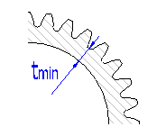
Minimum diameter of the shaft means the diameter of a solid shaft not weakened by grooves (see the illustration). Use the designed minimum diameter of the shaft as initial information for the design of the coupling.
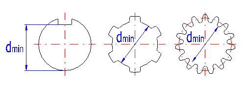
In the selection list, choose the type of material which will be used for production of the shaft. Minimum tensile strength [MPa/psi] and hardness of material are given in parenthesis. In case the checkbox to the right of the selection list is enabled, the necessary strength parameters for the chosen material are determined automatically. Otherwise, fill in the material characteristics manually. The value of the permitted pressure [1.19] is used for checks of contact surfaces of couplings for deformation. The permitted tension in shear [1.20] is used for strength checks of shafts in torsion.
In the selection list, choose the type of material which will be used for production of the hub. Min. tensile strength [MPa/psi] and hardness of material are given in parenthesis. In case the checkbox to the right of the selection list is enabled, the necessary strength parameters for the chosen material are determined automatically. Otherwise, manually fill in the value of the permitted pressure [1.24] which is used for checks of contacts surfaces of the coupling for deformation.
This coefficient reflects the effect of the coupling design on decrease of the coupling's loading capacity. It is determined according to empirical values given in the following table:
| Design of the coupling | Kd |
| Fixed coupling | 1 |
| Sliding coupling without loading | 3 |
| Sliding coupling with loading | 9 |
This coefficient reflects the effect of the character and type of loading on decrease of the coupling's loading capacity. It is determined according to empirical values given in the following table:
|
Drive |
Type of loading | |||
| Continuous | Light shocks | Cyclical shocks | Heavy shocks | |
| Uniform | 1.0 | 1.2 | 1.5 | 1.8 |
| Light shocks | 1.2 | 1.3 | 1.8 | 2.1 |
| Medium shocks | 2.0 | 2.2 | 2.4 | 2.8 |
This coefficient reflects effects of the operational character and desired service life of the coupling (measured in number of start-ups) on increase of the coupling's loading capacity. It is determined according to empirical values given in the following table:
| Number of start-ups | Operation | |
| Unidirectional | Fully bi-directional | |
| 1000 | 1.8 | 1.8 |
| 10000 | 1.0 | 1.0 |
| 100000 | 0.5 | 0.4 |
| 1000000 | 0.4 | 0.3 |
| 10000000 | 0.3 | 0.2 |
This coefficient reflects effects of wear of contact surfaces during the desired service life of the coupling (measured in number of revolutions) on increase of the coupling's loading capacity. It is determined according to empirical values given in the following table:
| Total number of revolutions [millions] | Kw |
| 0.01 | 4.0 |
| 0.1 | 2.8 |
| 1 | 2.0 |
| 10 | 1.4 |
| 100 | 1.0 |
| 1000 | 0.7 |
| 10000 | 0.5 |
Couplings with parallel side keys are suitable for transfer of torsional moments, mostly in the same direction of rotation. These couplings are used usually for immovable couplings of cylindrical shafts with hubs. This type is less suitable for sliding couplings and tapered shafts. Typical use is with clutches, sprockets and pulleys. Faces of the keys are usually rounded.
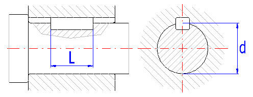
Benefits of the coupling:
Disadvantages of the coupling:
Loading capacity of the coupling can be increased by using 2 keys. However, this causes a significant weakening of the shaft and thus the possible use of a shaft with a greater diameter
| Type of bearing | Fixed couplings | Sliding couplings | ||
| Common bearing | Tight bearing | Guide key | Sliding key | |
| Seating of the key in the hub groove | N9 / h9 | P9 / h9 | N9 / h9 | D10 / h9 |
| Seating of the key in the shaft groove | Js9 / h9 | P9 / h9 | D10 / h9 | N9 / h9 |
| Seating of the hub on the shaft | H8 / h7
H8 / k7 H8 / m7 H8 / p7 |
H8 / f7
H8 / h7 H7 / h6 |
||
This paragraph can be used to choose the parameter of the given type of coupling and to design dimensions of the coupling.
In the selection list, choose a type (standard) of key. Dimensions of type A keys are defined by the standard in [in], dimensions of keys of other types are defined in [mm].
For transfer of higher torsional moments, it is possible to use two keys in the coupling. The keys are usually arranged symmetrically on the shaft (in opposite positions). A non-symmetrical arrangement is also used for transfer of cyclical moments (at 120° spacing).
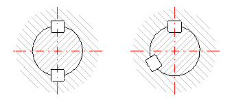
In couplings with two keys, the loading is not distributed exactly uniformly onto the two keys due to production and assembly inaccuracies. The actual load bearing surface of the coupling is lower than the load bearing surface determined theoretically. The ratio between the theoretical and actual load bearing surface of the coupling is defined by the coefficient of distribution of the loading. With regards to the accuracy of bearing, the size of the coefficient is given in a range from 0.6 to 0.8.
This coefficient gives the total effects of production and operational parameters on decrease of loading capacity of the coupling. Its size depends on the type of coupling, drive and loading, operational conditions and service lifespan of the coupling. With regards to the mentioned parameters, the literature gives values of the coefficient in a range from 1 to 40.
For easier choice of coefficient, the application is provided with automatic design. In case the checkbox to the right of the input field is enabled, the coefficient is determined automatically and based on parameters of the coupling defined in paragraph [1]. For a fixed coupling, the operational coefficient is calculated using the relation:

For a sliding coupling, the following relation is used:

where:
Ka - application factor
Kf - fatigue-life factor
Kd - coupling design factor
Kw - wear life factor
Meaning and size of the coefficients, see [1].
In the selection list, choose the type of the material which the key will be produced from. The min. tensile strength [MPa/psi] and hardness of material are given in parenthesis. In case the checkbox to the right of the selection list is enabled, the necessary strength parameters for the chosen material are determined automatically. Otherwise, manually fill in the value of the permitted pressure [2.9] which is used for checks of deformation of the key.
This paragraph can be used to design dimensions of the coupling. When designing the coupling, first choose the desired diameter of the shaft [2.14]. For the entered diameter of the shaft, the corresponding key will be chosen according to the respective standard automatically. For this chosen key, the program calculates the minimum length [2.20] which is necessary for safe transfer of the entered torsional moment. Complete the design of the coupling so that you choose the actual length of the key in row [2.22].
This parameter gives standard specified diameters of the shaft for the type of key chosen in [2.2].
This parameter gives the minimum diameter of a solid shaft, not weakened by a key groove, which is necessary for safe transfer of the entered torsional moment.
Choose a diameter of the shaft sufficient so that the diameter of a solid shaft d1, not weakened by a key groove, is larger that the minimum required diameter d1min.
The calculated minimum length of the chosen key, which is necessary for safe transfer of the entered torsional moment.
The standard specified minimum and maximum permitted length of the chosen key.
Choose a length of key within the standard specified range [2.21] so that it is larger than the minimum length [2.20]. When determining the length, keep in mind that the chosen length of the key influences the length of the hub. Recommended lengths of hubs can be found in the document "Guiding values for choices of dimensions of hubs".
In case of couplings with keys, there are usually performed only two types of strength checks. A check of loading of the shaft for torsion and a check of deformation of contact surfaces of the coupling. The check for loading of the key for shear is usually not performed. Standardized keys are dimensioned so that in case the requirements of the check for deformation are met, requirements of the check for shear stress are also met.
The check is performed for a diameter of a solid shaft d1 [2.18], not weakened by the key groove. The resulting safety of the coupling [3.4] is given by the ratio of the permitted shear stress of the shaft material to the calculated comparative stress. If the coupling is to be sufficient, the calculated safety must be higher than the required one [1.19].
The check for deformation is performed independently for each part of the coupling. Individual levels of safety [3.8, 3.12, 3.16] are given by the ratio of the permitted pressure of the respective material to the calculated comparative pressure acting on the given part of the coupling. In case the coupling is to be sufficient, the value of the lowest safety must be higher than the value of the required safety [1.19].
Couplings with Woodruff's (disk) keys are suitable for transfers of smaller torsional moments with shafts of smaller diameters mostly with the same direction of rotation. These couplings are used for fixed couplings of cylindrical or tapered shafts with short hubs. This type is usually not used for sliding couplings.
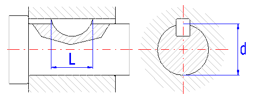
Benefits of the coupling:
Disadvantages of the coupling:
The loading capacity of the coupling can be increased using two keys. However, this causes a more significant weakening of the shaft and thus a possible need to use a shaft with a greater diameter.
| Type of bearing | Common bearing | Tight bearing |
| Bearing of the key in the groove of the hub | N9 / h9 | P9 / h9 |
| Bearing of the key in the groove of the shaft | Js9 / h9 | Js9 / h9 |
| Bearing of the hub on the shaft | H8 / h7
H8 / k7 H8 / m7 H8 / p7 |
|
This paragraph can be used for choices of parameters of the given type of coupling and for a design of dimensions of the coupling.
In the selection list, choose a type (standard) of key. Dimensions of the key are defined in the standard for types A, B, E, F v [in], in case of other types, the dimensions are defined in [mm]. Keys are produced in two basic designs (see the illustration):

Both types can be further designed with chamfered tops.

For transfer of higher torsional moments, it is possible to use two keys in the coupling. The keys are usually arranged symmetrically on the shaft (in opposite positions). A non-symmetrical arrangement is also used for transfer of cyclical moments (at 120° spacing).

In couplings with two keys, the loading is not distributed exactly uniformly onto the two keys due to production and assembly inaccuracies. The actual load bearing surface of the coupling is lower than the load bearing surface determined theoretically. The ratio between the theoretical and actual load bearing surface of the coupling is defined by the coefficient of distribution of the loading. With regards to the accuracy of bearing, the size of the coefficient is given in a range from 0.6 to 0.8.
This coefficient gives the total effects of production and operational parameters on decrease of loading capacity of the coupling. Its size depends on the type of coupling, drive and loading, operational conditions and service lifespan of the coupling. With regards to the mentioned parameters, the literature gives values of the coefficient in a range from 1 to 40.
For easier choice of coefficient, the application is provided with automatic design. In case the checkbox to the right of the input field is enabled, the coefficient is determined automatically and based on parameters of the coupling defined in paragraph [1]. For a fixed coupling, the operational coefficient is calculated using the relation:

For a sliding coupling, the following relation is used:

where:
Ka - application factor
Kf - fatigue-life factor
Kd - coupling design factor
Kw - wear life factor
Meaning and size of the coefficients, see [1].
In the selection list, choose the type of the material which the key will be produced from. The min. tensile strength [MPa/psi] and hardness of material are given in parenthesis. In case the checkbox to the right of the selection list is enabled, the necessary strength parameters for the chosen material are determined automatically. Otherwise, manually fill in the value of the permitted pressure [4.9] which is used for checks of deformation of the key.
The automatic design chooses all suitable keys for the chosen type [4.2] and additionally calculates the minimum sufficient diameter of the shaft for the keys. The design calculation is started by clicking the button in row [4.13]. After completion of the calculation, the table of designed solutions [4.14] is filled in and sorted and the values of the chosen solution are transferred automatically to paragraph [4.15]. The table is sorted according to the criterion set out in row [4.12] and can be re-sorted whenever using another chosen criterion.
If the design calculation was unsuccessful and no suitable solution was found, this fact is indicated by a warning message and the table of solutions is deleted. In such cases, repeat the design for a coupling with more keys or materials of a higher quality.
Meaning of parameters in the table:
| d | Diameter of the shaft |
| d1 | Diameter of a solid shaft not weakened by a key groove |
| L | Length of the key |
| sT | Safety of the strength check of a shaft for torsion |
| sp | Safety of the strength check for deformation |
| Key | Marking of the key (see [4.19]) |
This paragraph can be used to determine dimensions of the coupling. The dimensions can be chosen manually or the values of the designed solution can be transferred using a selection from table [4.14]. In case of values entered manually, first choose the desired diameter of the shaft [4.18]. After entering the shaft diameter the list of keys [4.19] assigned to the given diameter according to the respective standard is automatically filled in. Complete the design of the coupling by selecting a suitable key.
This parameter gives standard specified diameters of the shaft for the type of key chosen in [4.2].
This parameter gives the minimum diameter of a solid shaft, not weakened by a key groove, which is necessary for safe transfer of the entered torsional moment.
Choose a diameter of the shaft sufficient so that the diameter of a solid shaft d1, not weakened by a key groove, is larger that the minimum required diameter d1min. After entering the shaft diameter, a list of keys [4.19] assigned to the given diameter according to the respective standard is automatically filled in.
In the selection list, choose a suitable key. The list includes all keys assigned to the chosen diameter of the shaft [4.18] according to the respective standard. Marking of the keys in the list is given by the chosen type (standard) of key. The convention of marking for individual types of keys is given in the following table.
| Type of key [4.2] | Standard | Marking |
| A, B, E, F | ANSI B17.2, BS 6 | No. (b x D) |
| C, D, I, J | DIN 6888, CSN 30 1385 | b x h |
| G, H | JIS B 1301 | b x D |
where:
b - width of the key
h - height of the key
D - diameter of the key
In case of couplings with keys, there are usually performed only two types of strength checks. A check of loading of the shaft for torsion and a check of deformation of contact surfaces of the coupling. The check for loading of the key for shear is usually not performed. Standardized keys are dimensioned so that in case the requirements of the check for deformation are met, requirements of the check for shear stress are also met.
The check is performed for a diameter of a solid shaft d1 [4.22], not weakened by the key groove. The resulting safety of the coupling [5.4] is given by the ratio of the permitted shear stress of the shaft material to the calculated comparative stress. If the coupling is to be sufficient, the calculated safety must be higher than the required one [1.19].
The check for deformation is performed independently for each part of the coupling. Individual levels of safety [5.8, 5.12, 5.16] are given by the ratio of the permitted pressure of the respective material to the calculated comparative pressure acting on the given part of the coupling. In case the coupling is to be sufficient, the value of the lowest safety must be higher than the value of the required safety [1.19].
Couplings with straight-sided splines are suitable for transfer of great, cyclical and shock torsional moments. These couplings represent in practice the most common type of splines (approx. 80%). This type is used both for fixed and for sliding couplings of cylindrical shafts with hubs. These couplings are used typically in case of sliding gears in manual gearboxes.
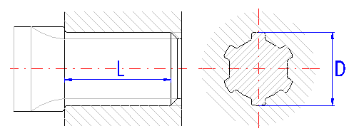
Benefits of the coupling:
Disadvantages of the coupling:
The method of centering is chosen according to technological and operational requirements and demands for accuracy. Centering is possible on the inner diameter (used rarely) or on sides of teeth. Centering on diameters is used in case of a need for higher accuracy of the bearing. Couplings centered on the sides show higher loading capacity and are suitable for loading with variable moments and shocks.
| Centering dimension | Bearing of the dimension | Note: | ||
| d | b | D | ||
| Fixed couplings at high loading with shocks, without frequent disassembly | ||||
| b | - | F8 / js7 | - | |
| Fixed couplings at medium loading and with frequent disassembly | ||||
| d | H7 / g6 | D9 / js7
D9 / k7 F10 / js7 F10 / f9 |
- | Medium speeds |
| b | - | F8 / js7 | - | Low speeds |
| D | - | F8 / js7 | H7 / js6 | High speeds |
| For movable couplings under loading | ||||
| d | H7 / f7
H7 / g6 |
D9 / h9
D9 / js7 F10 / f9 |
- | Hardened surfaces |
| For movable couplings without loading | ||||
| d | H7 / f7
H7 / g6 |
D9 / h9
F10 / f9 |
- | Low and medium speeds |
| D | - | F8 / f7
F8 / f8 |
H7 / f7 | High speeds |
where:
d - spline inner diameter
D - spline outer diameter
b - width of the teeth
This paragraph can be used to choose parameters of the given type of coupling and to design dimensions of the coupling.
In the selection list choose a type (standard) of splines. Spline dimensions are defined in the standard for types A, B, C in [in], in case of other types, the dimensions are defined in [mm].
| Type | Standard | Series | Use |
| A | SAE | A | Fixed couplings with low or medium loading |
| B | SAE | B | Sliding couplings without loading, couplings for transfer of large and cyclical moments |
| C | SAE | C | Sliding couplings under loading for transfers of large, cyclical and shock moments. |
| D | ISO 14 | Low | Fixed couplings with low or medium loading |
| E | ISO 14 | Medium | Sliding couplings, couplings for transfers of large and cyclical moments |
| F, I | DIN 5464
CSN 014942 |
Heavy | Sliding couplings under loading, couplings for transfers of large, cyclical and shock moments, automotive industry |
| G, H | DIN 5471
DIN 5472 |
Couplings for machine tools |
Due to production and assembly inaccuracies, the loading is not distributed uniformly onto all teeth of the spline. The actual load bearing surface of the coupling is smaller than the load bearing surface determined theoretically. The ratio between the theoretical and actual load bearing surface of the coupling is defined by the coefficient of distribution of the loading. With regards to accuracy of the bearing, the size of the coefficient is given in a range from 0.6 to 0.8.
This coefficient gives the total effects of production and operational parameters on decrease of loading capacity of the coupling. Its size depends on the type of coupling, drive and loading, operational conditions and service lifespan of the coupling. With regards to the mentioned parameters, the literature gives values of the coefficient in a range from 1 to 40.
For easier choice of coefficient, the application is provided with automatic design. In case the checkbox to the right of the input field is enabled, the coefficient is determined automatically and based on parameters of the coupling defined in paragraph [1]. For a fixed coupling, the operational coefficient is calculated using the relation:

For a sliding coupling, the following relation is used:

where:
Ka - application factor
Kf - fatigue-life factor
Kd - coupling design factor
Kw - wear life factor
Meaning and size of the coefficients, see [1].
This paragraph can be used to design dimensions of the coupling. When designing a coupling, first choose dimensions of the spline [6.8]. For the chosen spline, the program calculates its minimum functional length [6.14], which is necessary for safe transfer of the entered torsional moment. Complete the design of the coupling by choosing the actual length of the spline in row [6.15].
This parameter gives a standard given range of outer diameters of spline for the chosen series of splines [6.2].
This parameter gives the minimum diameter of a solid shaft, not weakened by splines, which is necessary for safe transfer of the entered torsional moment.
In the selection list, choose a spline of suitable dimensions. Choose the spline so that the inner diameter of spline d is greater than the minimum diameter dmin. Dimensions of spline are given in the list in the following form: "Outer diameter" - "Prescribed marking". The convention of marking for individual types of splines is given in the following table.
| Type of splines [6.2] | Marking |
| A, B, C | D x n |
| D - I | n x d x D |
where:
n - number of grooves
d - spline inner diameter
D - spline outer diameter
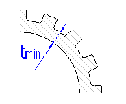
The parameter gives the minimum functional length of the chosen spline, which is necessary for safe transfer of the entered torsional moment.
Choose a length of spline greater than the calculated minimum length [6.14]. When determining the length, keep in mind that the chosen length of the spline is at the same time the minimum permissible length of the hub. Recommended lengths of hubs can be found in the document "Guiding values for choices of dimensions of hubs".
In case of splined couplings, only two types of strength checks are usually carried out. A check of loading of the shaft for torsion and a check of deformation of contact surfaces of the coupling.
The check is carried out for the diameter of a solid shaft d, not weakened by splinines [6.10]. The resulting safety of the coupling [7.4] is given by the ratio of the permitted shear stress of the shaft material to the calculated comparative stress. If the coupling is to be sufficient, the calculated safety must be higher than the required one [1.19].
The check for deformation is carried out by comparison of the permitted pressure of a material of lower quality with the calculated comparative pressure acting on the sides of the groove. If the coupling is to be sufficient, the calculated safety must be higher than the required one [1.19].
Couplings with involute splines are suitable for transfers of great, cyclical and shock torsional moments. This type is used both for fixed and for sliding couplings of cylindrical shafts with hubs. The use is similar as with straight-sided splines.
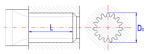
General benefits of the coupling:
Benefits of the coupling compared with Straight-sided spline:
Disadvantages of the coupling:
The splined profile is shaped as involute toothing in the cross section, with basic angles of the profile 30°, 37.5° or 45°. It is centered to the outer diameter or sides of the teeth. Centring to the diameter is more accurate, centring to sides is more economical and is used much more frequently in practice The groove bottom can be flat or rounded.

| Centering dimension | Bearing of the dimension | Note | |
| t | Do | ||
| Immovable couplings at high loading with shocks, without frequent disassembly | |||
| t | 7H / 9r
7H / 8p 7H / 7n |
H11 / h11 | |
| Immovable couplings at medium loading, disassembled frequently | |||
| t | 7H / 8k
7H / 9h |
H11 / h12 | Low speeds |
| Do | 9H / 9h
9H / 9g 9H / 9d |
H7 / n6
H7 / js6 |
High speeds |
| For movable couplings | |||
| Do | - | H7 / h6
H7 / g6 H7 / f7 |
Hardened surfaces |
where:
Do - outer diameter of external spline
t - width of the teeth
This paragraph can be used for options of parameters of the given type of coupling and to design dimensions of the coupling. As marking of individual dimensions of spline is different in various standards, the calculation uses marking according to ANSI B92.1 and the differences in marking are given in the following table:
| ANSI B92.1 | ANSI B92.2M
ISO 4156 |
DIN 5480
CSN 4950 |
|
| Diametral pitch | P | - | - |
| Module | - | m | m |
| Number of teeth | N | Z | z |
| Pitch diameter | D | D | d |
| Base diameter | Db | DB | db |
| Reference diameter | - | - | D |
| Shift of basic profile | - | - | xm |
| Major diameter of external spline | Do | DEE | da |
| Minor diameter of external spline | Dre | DIE | df |
| Minor diameter of internal spline | Di | DII | Da |
| Major diameter of internal spline | Dri | DEI | Df |
| Tooth thickness | tv | SV | s |
| Groove width | sv | EV | e |
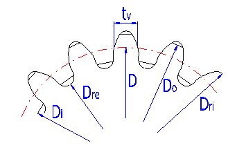
In the selection list, choose a standard and a type of spline. Dimensions of spline are defined for types A to E by the standard in v [in], in case of other types the dimensions are defined in [mm]. Individual types of spline are described in the list as follows: "Standard of spline" - "Angle of the profile", "Design of the spline", "Centering method".
Due to production and assembly inaccuracies, the loading is not distributed uniformly onto all teeth of the spline. The actual load bearing surface of the coupling is smaller than the load bearing surface determined theoretically. The ratio between the theoretical and actual load bearing surface of the coupling is defined by the coefficient of distribution of the loading. With regards to accuracy of the bearing, the size of the coefficient is given in a range from 0.4 to 0.8.
| KL | Design of spline |
| 0.75 | Fixed couplings with short lengths and high accuracy of bearing |
| 0.6 - 0.7 | Couplings with normal accuracy of bearing |
| 0.5 | Sliding couplings with great lengths of contact surfaces and great non-alignment of the coupling |
This coefficient gives the total effects of production and operational parameters on decrease of loading capacity of the coupling. Its size depends on the type of coupling, drive and loading, operational conditions and service lifespan of the coupling. With regards to the mentioned parameters, the literature gives values of the coefficient in a range from 1 to 40.
For easier choice of coefficient, the application is provided with automatic design. In case the checkbox to the right of the input field is enabled, the coefficient is determined automatically and based on parameters of the coupling defined in paragraph [1]. For a fixed coupling, the operational coefficient is calculated using the relation:

For a sliding coupling, the following relation is used:

where:
Ka - application factor
Kf - fatigue-life factor
Kd - coupling design factor
Kw - wear life factor
Meaning and size of the coefficients, see [1].
The automatic design selects the 20 best solutions for the chosen type and series of spline in view of the requirement for the minimum diameter of the shaft. The length of spline is chosen with regards to the recommended dimensions of the hub. The design eliminates all solutions where the length of the hub results in more than a doubling of the outer diameter of spline.
The design calculation is started by clicking the button in row [8.9]. After completion of the calculation, the table of designed solutions [8.10] is filled in and sorted and the values of the chosen solution are transferred automatically to paragraph [8.11]. The table is sorted according to the criterion set out in row [8.7] and can be re-sorted whenever using another chosen criterion.
In case the design calculation was unsuccessful and no suitable solution was found for the entered values, this fact is indicated by a warning message and the table is deleted. In such cases, repeat the design for a coupling with materials of a higher quality.
In the list, choose a range of input data (spline dimensions) used by the automatic design for selection of a suitable solution.
When enabling the checkbox, the design eliminates all solutions where the length of the hub results in a higher value than the entered value Lmax.
Meaning of parameters in the table:
| m/P | Module or pitch of the spline resp. (according to the splines type) |
| n | Number of teeth |
| Do | Major diameter of external spline |
| Dre | Minor diameter of external spline |
| Lmin | The minimum functional length of spline which is necessary for safe transfer of the entered torsional moment. |
| L | The chosen length of spline |
| sT | Safety of the strength check of the shaft for torsion |
| sp | Safety of the strength check for deformation |
This paragraph can be used to determine dimensions of the coupling. The dimensions can be chosen manually or the values of the designed solution can be transferred using a selection from table [8.10]. When entering the values manually, first choose a suitable dimension of spline [8.13].
For the chosen spline, the program calculates its minimum functional length [8.21], which is necessary for safe transfer of the entered torsional moment. Complete the design of the coupling by choosing the actual length of the spline in row [8.22].
This parameter gives the minimum diameter of a solid shaft, not weakened by splines, which is necessary for safe transfer of the entered torsional moment.
In the selection list, choose a spline of suitable dimensions. Choose the spline so that the inner diameter of spline Dre is greater than the minimum diameter Dremin. Spline dimensions are given in the list as follows: "Outer diameter" - "Module / Pitch" x "Number of teeth". Preferred (recommended) dimensions of spline are marked in the list using the symbol "*".
The parameter gives the minimum functional length of the chosen spline, which is necessary for safe transfer of the entered torsional moment.
Choose a length of spline greater than the calculated minimum length [8.21]. When determining the length, keep in mind that the chosen length of the spline is at the same time the minimum permissible length of the hub. Recommended lengths of hubs can be found in the document "Guiding values for choices of dimensions of hubs".
In case of splined couplings, only two types of strength checks are usually carried out. A check of loading of the shaft for torsion and a check of deformation of contact surfaces of the coupling.
The check is carried out for the diameter of a solid shaft Dre, not weakened by splines [8.17]. The resulting safety of the coupling [9.4] is given by the ratio of the permitted shear stress of the shaft material to the calculated comparative stress. If the coupling is to be sufficient, the calculated safety must be higher than the required one [1.19].
The check for deformation is carried out by comparison of the permitted pressure of a material of lower quality with the calculated comparative pressure acting on the sides of the groove. If the coupling is to be sufficient, the calculated safety must be higher than the required one [1.19].
This paragraph can be used for a fast comparison of designed solutions of couplings of shafts with hubs. Only basic dimensions are given here for individual types of couplings. Complete dimensions of the coupling can be found in the independent chapter (section) of the respective calculation.
Information on options of 2D and 3D graphic outputs and information on cooperation with 2D and 3D CAD systems can be found in the document "Graphic output, CAD systems".
Information on setting of calculation parameters and setting of the language can be found in the document "Setting calculations, change the language".
General information on how to modify and extend calculation workbooks is mentioned in the document "Workbook (calculation) modifications".
^