The calculation solves area characteristics of common profiles and mass characteristics of solids created by drawing or rotation of the profile.
The application enables:
User interface.
Download.
Purchase, Price list.
Information on the syntax and control of the calculation can be found in the document "Control, structure and syntax of calculations".
Controlling this calculation is slightly different from that of common calculations. The calculation sheet is divided into three parts. The upper (fixed) part includes command buttons, parameters setting the graphic editing area and a scale. A description of drawing commands is given below.
Information on the purpose, use and control of the paragraph "Information on the project" can be found in the document "Information on the project".
Despite the fact that calculating characteristics is a simple task, a brief description of the procedure is given here.
The area for drawing the profile consists of 220 rows x 220 columns with small spacing. Cells in this area are colorless. The profile is created so that the selected cells are filled with the selected color. The X axis is horizontal axis, the Y axis is the vertical axis. The point 0,0 is situated in the lower left hand corner of the drawing area.
Command buttons are situated in the upper part of the sheet. After pressing the button, the selected shape is drawn into the selected area in the drawing field.
Procedure:
Example: Drawing a filled elliptic arch
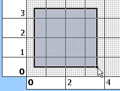

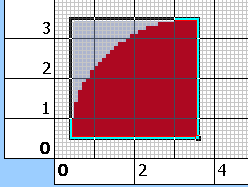

In case you use the standard Excel command for copying cells with creation of the profile, the millimetre grid can be damaged. This command restores the standard grid in the drawing area.
In the list box, select the color which will be used for drawing the shape.
The command fills the selected rectangle area with the preset color.
The command removes color from the selected area.
The command fills the selected square (rectangle) area with a circle (ellipse).
The command removes the circle (ellipse) shape from the selected square (rectangle) area.
The command fills the selected area with a triangle shape - chamfer. The triangle is turned according to one of the four buttons.
The command fills the selected area with a quadrant - rounding. The quadrant is turned according to one of the four buttons.
The command creates a mirror image of the selected area in the defined direction. The mirror image is created along the respective margin of the selective rectangle.
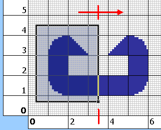
The button initiates calculation of characteristics.
The calculation is executed in the VBA module. All cells of the editing area are processed consecutively and if a cell is colored, it is included in the calculation.
Standard formulas and procedures with calculations (Integration of the area, calculations of Ix, Ixy, Ip, Sx, gravity centre, area, etc.) are used as available in
specialized literature.
The calculation can be initiated using the button "Calculation of the profile" in the upper right hand corner of the calculation sheet.
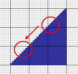
When creating oblique lines and curves, these are replaced by a "polygonal line". This affects the accuracy of the calculation. It is generally applicable for profiles containing oblique lines: The greater the size of the profile compared with the size of the drawing area, the smaller the error in the calculation. Try to set the scale of the grid so that the calculated profile fills as large an area of the drawing field as possible.
These are given in actual co-ordinates, measured from the point 0,0. The small button at the end of the row ">" places the cursor (selects a cell) in the centre of gravity.
The moment of inertia Ix (Iy) is related to the axis which goes through the centre of gravity and is parallel with the X (Y) axis.
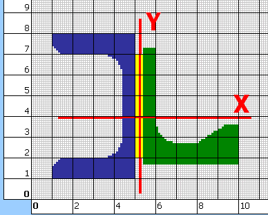
It is related to the centre of gravity.
It is related to the centre of gravity.
It is the minimum / maximum value Ix to the axis going through the centre of gravity and forming an angle with the X axis.
It is an important quantity which is decisive in finding of the maximum bending stress acting in a beam with the given profile. The value Sx is calculated according to the formula Sx=Ix/a, where a is the distance between the straight line going through the centre of gravity and the position of the extreme fibre.
Two values for the axis X and two values for the axis Y are given here. The value with the sign "+" Sx+, (Sy+) is related to the upper (right) extreme fibre. The value with the sign "-" is related to the lower (left) extreme fibre.
The graph shows dependences of the "Moment of inertia" and "Bending modulus of section" to the bending angle of the profile around the centre of gravity. The bending angle is drawn on the horizontal axis. The vertical axis on the left includes values Ix, the vertical axis on the right includes values Sx+(extreme upper fibre) and Sx-(extreme lower fibre).
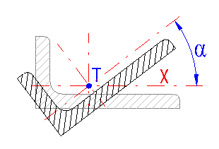
In this paragraph you can calculate area characteristics of the profile to shifted and turned axes. Marking according to the illustration.
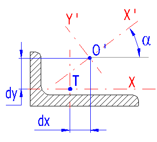
Enter shifts of the axes of which area characteristics you wish to find.
Enter an axis rotation angle.
These are related to X' and Y' axes (or to the point O' resp.) turned by the angle.
In this paragraph you can find volume parameters of the solids which will be created by drawing or rotation of the created profile.
Enter the density of the material of the beam (or the solid of rotation resp.). Some common materials are given in the list box to the right of the input field.
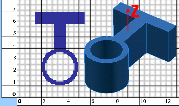
Enter the desired length of the beam created by extraction of the drawn profile in the direction of the axis Z.
It is the moment of inertia of the beam to the axis Z. The Z axis is perpendicular to the area of the section and goes through the profile's centre of gravity.
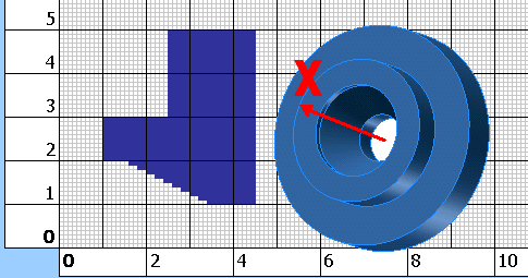
It is a mass moment of inertia of the solid of rotation (created by rotation of the profile around the X axis) to the X axis.
Information on setting of calculation parameters and setting of the language can be found in the document "Setting calculations, change the language".
General information on how to modify and extend calculation workbooks is mentioned in the document "Workbook (calculation) modifications".
Except for possible formatting of numbers, no other modifications to this workbook are recommended.
^