This program (algorithm) is used to design and check power screws. It is used to solve the following tasks:
1. Calculation of kinematic parameters (speed, torque, revolutions and power output...)
2. Simple selection / definition of power screw (metric, square, trapezoidal...)
3. Screw check for tensile/pressure, thrust, bend, buckling and critical revolutions.
4. The program contains a table of materials, threads and friction coefficients.
5. Support of 2D CAD systems.
The calculation is based on data, procedures and algorithms from specialized literature and AGMA, ISO, DIN and BS standards.
List of standards: ISO 68-1,
68-2,
ISO 724, ISO 965, ISO
2904: 1977, DIN 513, CSN 01 4050, CSN 01
4052, ANSI/ASME B1.5-1977, ANSI/ASME B1.9-1973, ASME B1.1-2003, IS 4694-1968....
Literature: Mechanical engineering design (Konstruování strojních součástí), Textbook of Machine Design, Machinery’s Handbook 26th Edition, Části a mechanismy strojů.
![]()
User interface.
![]()
Download.
![]()
Purchase, Price list.
Information on the syntax and control of the calculation can be found in the document "Control, structure and syntax of calculations".
Information on the purpose, use and control of the paragraph "Information on the project" can be found in the document "Information on the project".
Power screws are used to convert rotating motion into linear motion (in certain cases from linear to rotating motion). They are used as guide screws for lathes, vices, presses, power lifts, etc.
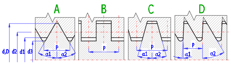
Several types of threads are used for power screws, for example:
A. Metric / UNC, UNF, UNEF - is the most common thread. It is produced in two/three dimensionally standardized series. They are marked with the letter M and a large thread diameter – for example: M24 (or rather Dimension - UNC-x, where x is the number of thread turns per inch). It is used for power screws but only to a limited extent due to its large thread angle. It is suitable for positioning or for mechanisms which bear small loads.
B. Square thread - It is not standardized, has no established marking/labeling and the dimensions of the thread profile must be specified in detail. Demanding on production, precision... Used for lightly stressed, manually controlled mechanisms.
C. Trapezoidal thread - It has a profile in the shape of an isosceles trapezoid and it is used to drive feeds of machines, slides, power lifts, etc. It is marked with the letters Tr, with the outer diameter and pitch. (Tr 22 x 8). Inch threads are marked by using the outer (nominal) diameter, by the number of thread turns per inch and the profile(1.750-4-ACME-...). This is the most used thread for power screws. It offers an advantage when compressive force is used in both directions.
D. Buttress Coarse Thread - It has the same use as an isosceles thread. Only its profile has the shape of an unequal trapezoid. It is marked with the letter S, the outer diameter and pitch. Used for screws which bear heavy loads in one direction (extruders, presses, power lifts...)
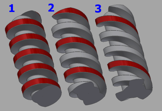
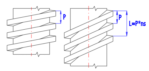
Regular Metric / UNC, UNF, UNEF threads are manufactured as single-start (single-lead) threads. Power screws are also produced as multi-start threads. Multi-start threads have greater efficiency, faster feed, but they lose the self-locking ability. See the pictures showing single, double and triple start threads with the same pitch P.
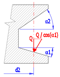
Single-start, square screw loaded with force Q.
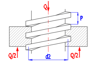
Distribution of forces acting in a screw connection along the length of one thread:
Inclusion of the effect of thread surface angle a1 (a2)
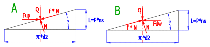
Formulas for torque calculation.
To lift (Figure A):
Mkup [Nm] = Q * d2/2 * ((L * COS(a1) + p * f * d2) / (p * d2 * COS(a1) - f * L)) / 1000 + Mkj
To release (Figure B):
Mkdw [Nm] = Q * d2/2 * ((p * f * d2 - L * COS(a1)) / (p * d2 * COS(a1) + f * L)) / 1000 + Mkj
where:
Q ................ load force [N]
d2 ............... screw pitch diameter [mm]
a1,(a2) ..... apex angle of the thread profile [º]
f ................. coefficient of friction [~]
L ................ pitch [mm]
Mkj ............. additional pin friction torque [Nm]
Thread pitch L
Multi-start threads are often used for power screws Thread pitch L is then a multiple of the pitch and the number of thread starts.
L [mm] = P * ns
where:
P – thread pitch [mm]
ns – number of thread starts [~]
Friction coefficient f
Values used for lubricated thread.
0.06 - 0.09 ... Hardened steel / Bronze
0.08 - 0.09 ... Steel / Bronze
0.11 - 0.17 ... Steel / Steel
0.11 - 0.17 ... Steel / Cast Iron
Often a flange is attached to a screw (nut) to absorb the axial force (power lifts, vices...), which causes additional friction and which must be taken into account when checking the strength of the screw. In case of high loads, roller bearings are preferred, where the additional torque is minimal and can be neglected during the check.
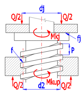
Mkj [Nm] = Q * fj * (dj / 1000) / 2)
where:
Q ...... load force [N]
dj ...... mean pin diameter [mm]
fj ...... coefficient of friction [~]
Friction coefficient fj
Values used for lubricated
friction
0.06 ............ Hardened steel / Bronze
0.08 ............ Steel / Bronze
0.09 ............ Hardened steel / Cast iron
0.12 ............ Steel / Cast Iron
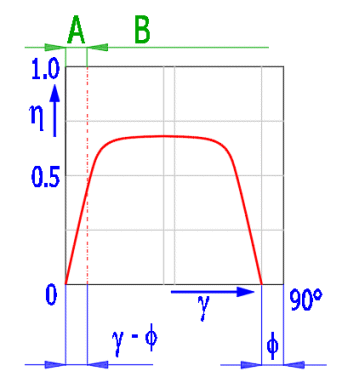
Efficiency
It is calculated as the ratio between the work done by lifting a load and the work performed by the applied torque.
h = Q * (L / 1000) / (2 * p * Mkup)
The efficiency increases with increasing pitch angleg. The theoretical diagram below does not include the effect of pin friction, thread groove angle and other factors. Area A represents the self-locking area of the screw. Friction angle f = atan (coefficient of friction).
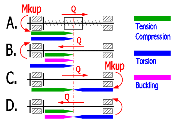
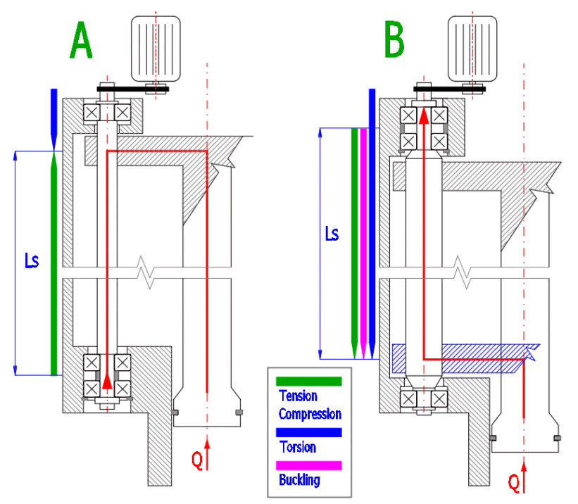
By choosing a proper structural design it is possible, for example, to eliminate the buckling load of the screw, pin friction as well as combined stress, etc. Examples in the picture show how it is possible to change the least favorable stress combination – variant B (pressure + torsion, buckling) into a more favorable variant C (simple tensile stress, torsion). The calculation contains all commonly performed checks and the type of the structural design determines their evaluation.
t [MPa] = 16 * Mkup / (p * (d3 / 1000)3) / 1000000
where:
Mkup ..... lifting torque [Nm]
d3 ......... screw core diameter [mm]
s [MPa] = 4 * Q / (p *(d3 / 1000)2) / 1000000
where:
Q – load force [N]
d3 – screw core diameter [mm]
sred [MPa] = (s2 + 3 *
t2)0.5
Safety
coefficient SF = Rp(0.2) /
sred
Screws loaded by axial force are divided into three basic groups.
A.
Short screws
-
failure/deformation occurs when the yield point in compression is achieved. The
screws
are strained by simple compression.
B.
Medium-length
screws
– are deformed in the area of inelastic buckling according to rather complicated
relations and regularities. There are many theories and empirical methods
dealing with calculation of critical force/stress.
C.
Long beams (struts)
–failure/deformation occurs significantly earlier than the stress exceeds
permitted stress of the material. The failure appears as buckling and collapse
of the strut.
A number of procedures are used to check the buckling stress (see picture). The screw calculation uses the Secant method to calculate the stress at the edge fiber profile. This method also allows you to address cases when the force does not act exactly along the axis of the screw (imperfections of the bearing mount), or when the screw is not perfectly straight (manufacturing inaccuracies, deflection).
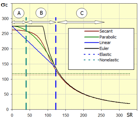
In the diagram (critical stress sc dependent on slenderness ratio of the strut SR), letters A, B and C determine areas of simple compression (A), nonelastic buckling (B) and elastic buckling (C).
The slenderness ratio of the SR screw refers to basic geometric characteristics of the checked screw expressed by the following formula:
SR [~] = Leff / (Ix / A)0.5
where:
Reduced
(effective) screw length Leff [mm] = Ls * elc
Ls......screw
length [mm]
elc.....coefficient of reduced (effective) length [~]
Ix......quadratic
moment of
inertia [mm4]
A.......profile
area [mm2]
Secant formula for calculation of stress in the extreme fibre of the profile:
s [MPa] = Q / A * (1 + (e * y / rx2)
* sec (Leff / (2 * r) * (Q / (E * A))0.5))
where:
Q.......force[N]
Leff .. reduced
(effective) screw length [mm]
A.......profile area [mm2]
E.......modulus of elasticity in tension [MPa]
rx......gyration radius [mm]
y.......extreme fibre distance [mm]
e.......deflection of origin of force or screw
axis [mm]
Equation in the brackets (e
* y / rx2)
formulates the so-called eccentricity degree -
m.
With expected knowledge of
m
(estimation), the Secant formula is a very good substitution of the said
empirical methods and is a basis for the whole range of suggested methods.
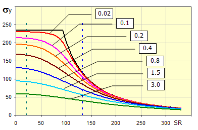
The diagram of critical stress
sc
dependent on slenderness rate of the strut SR shows curves for various values of
eccentricity degree -
m.
After iterating the formula by changing the Q to reach s= Rp (0.2), we obtain the critical force Qcr
Safety coefficient SF = Qcr / Q
Depending on the SR, the basic recommended safety values are:
A. SR < SRcs..............Area
of simple compression.
Recommended safety SF>1.75)
B. SRcs < SR < SRc.....Area
of
nonelastic
buckling. Recommended safety
SF=1.75*(1+(SR - SRcs) / (SRc - SRcs))
C. SRc < SR................Area
of
elastic buckling. Recommended
safety SF>3.5)
Experiments show that the first functional thread carries 38% of the load, the second 25%, the third 18% – and the eighth (in some cases even the fifth) the thread bears no load
The thrust check can be performed as follows. Thread pressure p:
p [MPa] = 4 * Q / (p * (d2 - d12) * nz)
where:
Q.......force[N]
d ..... outer diameter of the screw
thread [mm]
d1 ... inner diameter of the nut thread [mm]
nz .... number of active threads in the nut
The formula is:
ncr = 946 * K * (1 / ymax)^0.5
where:
ymax ... deflection of the screw in [mm] from its own weight depending on the screw mount
K ......... shaft bearing coefficient
In case of a large pitch L of the thread or in case of a small friction f, the screw may start rotating unintentionally. It is possible to calculate the limiting angle for the self-locking property of the thread, which, however, does not include other factors, such as the pin friction of the support flange.
In this case, the determining value is the torque Mkdw (torque initiating the release). If this value is negative, there is a high probability that the screw will rotate spontaneously due to the load force Q.
The calculation and inspection of the screw usually consists of the following steps.
1. Select the screw and nut material [1.2, 1.3]
2. Define the screw load and feed rate [1.4, 1.5]
3. Select the thread type and size [1.8, 1.9]
4. Inspect the strength checks in [2.0]
5. If the checks do not comply, change the size of the screw or the material.
6. Save the workbook with the proposed solution under a new name.
In this section you define the load, kinematics and force ratios of the screw.
Select the desired system of calculation units in the list box. After switching over the units, all values will be changed immediately.
Select the material from the list. Based on the selected materials, the coefficient of friction in the threads will be set [1.6]. Further, the value of density, modulus of elasticity and yield strength in check calculations will be preset [2.0]
Enter the load force on the screw/nut.
Enter the required screw/nut feed speed. Depending on the selected screw type and size, the corresponding revolutions will be calculated. If you know the revolutions, enter the value on line [1.28]. The feed rate will be calculated retrospectively.
Enter the assumed coefficient of friction in threads. Depending on the selected materials, the corresponding value for the lubricated connection is preset. The recommended values are as follows:
Screw / Nut
0.11 - 0.17 ... Steel / Steel
0.10 - 0.16 ... Steel / Bronze
0.10 - 0.15 ... Steel / Brass
0.11 - 0.17 ... Steel / Cast Iron
0.08 - 0.12 ... Bronze / Steel
0.04 - 0.06 ... Bronze / Bronze
0.06 - 0.09 ... Bronze / Cast Iron
Based on the load force and the selected materials, the pitch diameter d2 is estimated. This is a guide for selecting the appropriate screw size.
Select the thread type and size from the drop-down lists.
After selecting the thread size, its normalized parameters are filled in the following lines. If you uncheck the button on the right, you may fill in your own thread dimensions. You can follow the picture on the right when defining dimensions.
A multi-start thread is often used for power screws (faster movement/feed, greater efficiency...).
The pitch is the multiplication product of the number of thread starts and the pitch. Important characteristic dimension of the screw.
It is the angle between the pitch of the thread and the circumference of the screw on the pitch circle.
Except for the unequal trapezoid thread, the angles are symmetrical. In the case of an asymmetrical angle, the angle a1 is used to calculate the kinematic and strength parameters (this should be the smaller angle used on the loaded side).
If the axial force is absorbed by the friction element, you may enter its parameters. In this case, the pin friction has a significant effect on the efficiency, self-locking, load-bearing capacity and other parameters of the power screw.
Enter the coefficient of friction in the pin / roller bearing. Approximate values for lubricated friction are below.
0.05-0.10 ... Hardened steel / Hardened steel
0.05-0.15 ... Hardened steel / Cast iron
0.09-0.15 ... Hardened steel / Phosphore bronze
0.07-0.10 ... Cast iron / Cast iron
0.07-0.10 ... Cast iron / Phosphore bronze
0.20-0.25 ... Cast iron / Wood (oak)
0.07-0.10 ... Phosphore bronze / Phosphore bronze
0.0015 … Deep groove ball bearings, single row
0.0015 … Deep groove ball bearings, double row
0.0020 … Angular contact ball bearings, single row
0.0024 … Angular contact ball bearings, double row
0.0010 … Self-aligning ball bearings, with cylindrical bore
0.0011 … Cylindrical roller bearings, single row
0.0025 … Needle roller bearings, with inner ring
0.0018 … Taper roller bearings, single row
0.0018 … Spherical roller bearings, with cylindrical bore
0.0013 … Thrust ball bearings
0.0050 … Cylindrical roller thrust bearings
0.0050 … Needle roller thrust bearings
0.0018 … Spherical roller thrust bearings
Enter the mean diameter of the pin or the inside diameter of the bearing.
Additional torque that puts stress on the power screw and on the entire kinematics of the movement.
It is the force that must be executed in order to lift the load or rather to create the required axial force.
It is the force that must be executed to lower the load or rather to release the required force.
An important parameter for assessing the correct design of the power screw.
Drive power required to lift the load or to execute the required force.
Based on the entered feed speed and the screw geometry, the required revolutions are calculated. However, it is often necessary to solve the opposite problem – when we know the revolutions of the screw (nut) and we need to calculate the feed speed. In this case, enter the revolutions and use the "<<" button to calculate the corresponding feed speed.
Speed on the outer diameter of the screw. It can be used as a guide when evaluating the design.
If you need to determine the value or length of the nut (screw) movement depending on the number of revolutions (screw rotation), select and enter the appropriate value on line [1.32, 1.33].
By choosing a proper structural design it is possible, for example, to eliminate the buckling load of the screw, pin friction as well as combined stress, etc. Examples in the picture show how it is possible to change the least favorable stress combination – variant B (pressure + torsion, buckling) into a more favorable variant C (simple tensile stress, torsion). The calculation contains all commonly performed checks and the type of the structural design determines their evaluation.
Enter the length of the screw according to the proposed structural design.
Material parameters are preset based on the choice of screw and nut material [1.2, 1.3]. However, the specific material values may vary slightly. After unchecking the button on the right, you can enter your own values.
Its value depends on the combination between the materials, surface treatment, method of lubrication, etc. The recommended value includes the effect of material and speed for the lubricated connection.
The following values may be used to estimate lubricated connection:
Screw
/ Nut
Hardened Steel / Bronze ...... 10 - 15 MPa (1.45 - 2.20 kpsi)
Steel / Bronze ................. 8 - 10 MPa (1.15 - 1.45 kpsi)
Steel / Steel ................... 7 - 12 MPa (1.00 - 1.75 kpsi)
Steel / Gray Cast Iron ............ 4 - 6 MPa (0.58 - 0.75kpsi)
At increased speeds, the values must be reduced. For example, for the Steel/Bronze combination, the allowed pressure is as follows:
Speed
0.05 m/s (2.0 in/s) ................ 11-17 MPa (1.60 - 2.50 kpsi)
0.1 - 0.2 m/s (4 - 8 in/s) ......... 5-10 MPa (0.75 - 1.45 kpsi)
0.25 m/s (10 in/s) .................... 1-2 MPa (0.15 - 0.30 kpsi)
Limiting slenderness SRc is an
important parameter of a specific material, distinguishing the area of elastic
and inelastic buckling as well as the use of relevant equations. It is,
therefore, suitable to verify the parameter for the specific material. The
recommended value is determined according to the equation:
SRcs = 0.5 * (E / (Rp02 * 0.5))0.5
SRc = (E *
p2
/ (Rp02 * 0.5))0.5
Depending on the type of structural design, the following values must be checked.
Torsional stress in the screw core. It should be less than the allowed stress in the cell marked in green.
Tensile/Compressive stress in the screw core.
In case of simultaneous action of tensile stress / pressure and torsion, it is necessary to deal with combined stress and loads. The reduced stress should be less than the allowed tensile stress.
It is related to the equivalent stress.
If the screw also bears compressive stress, it is also necessary to check long screws for buckling. The need for this check depends on the slenderness ratio [2.23]
In the list box, select the type of screw mounting according to the picture. The selection of the type of mounting leads to selection of a coefficient of reduced (effective) length that is used to multiply the real screw length to achieve so-called reduced (effective) screw length used in calculations. Line [2.15] specifies the engineering value recommended to be used in the calculation.
Screw mounting .......... Coef.(theor) / Coef.(pract)
A. Clamped - Clamped ............
0.50 /
0.65
B. Clamped - Hinged
............... 0.70
/
0.80
C. Clamped - Guided
............... 1.00
/
1.20
D. Hinged - Hinged
................. 1.00
/
1.00
E. Clamped - Free end
.............
2.00
/
2.10
F. Hinged - Guided
.................. 2.00
/
2.00
Depending on bearing type
Plain bearings (d -
diameter, l - length)
l / d <2 .............. hinged (support)
2 <l / d < 3 ........ limited rotation
l / d> 3 .............. clamped
Rolling bearings
Single row deep groove ball bearing, self-aligning ball bearings
................... hinged (support)
Cylindrical roller bearings, deep groove ball bearings, double row
................ limited rotation
Pair of tapered roller bearings, radial + thrust bearing ................................
clamped
The value is used in calculations. It is the actual length [2.1] multiplied by the reduced (effective) length coefficient [2.16].
It is the distance of the extreme fibre from the profile axis which goes through the centre of gravity. This value is required for calculation using the "Secant" method.
The slenderness ratio of a specific beam determines which buckling zone the beam is in (simple compression, inflexible buckling, flexible buckling) and thus also the check method used for determination of the safety coefficient.
A. SR < SRcs..............Area
of simple compression.
Recommended safety SF>1.75)
B. SRcs < SR < SRc.....Area
of
nonelastic
buckling. Recommended safety
SF=1.75*(1+(SR - SRcs) / (SRc - SRcs))
C. SRc < SR................Area
of
elastic buckling. Recommended
safety SF>3.5)
The degree of inaccuracy of a structure and load for the design of screw dimensions may be determined using this parameter. The parameter includes:
Deviation of screw straightness
Initial screw sag
Origin of forces outside the screw axis
Recommended values:
0.25...steel structures
0.15...general engineering
0.05...accurate rigid mountings
Eccentricity “e” is calculated based on the degree of eccentricity [2.24]. If you know the values of deflection, inaccuracy, etc., enter the value on the right and press the "<<" button and the system will calculate the degree of eccentricity.
It expresses the ratio between critical and acting force. An adequate safety coefficient (green cell) is recommended based on the slenderness ratio [2.23]
It indicates the deflection of the screw due to the weight of the screw and based on the mount.
The number of active threads is calculated using the selected nut height. Based on the force and dimensions of the screw and the number of threads, the pressure in the threads is calculated.
Select the height of the nut. The green cell shows the recommended value which is based on the knowledge that the actual transfer of force is done by no more than 8 threads.
Number of threads in the nut depending on the pitch and height of the nut. After entering the required number of threads and after pressing the "<<" button, the height of the nut is calculated.
Experiments show that the first functional thread carries 38% of the load, the second 25%, the third 18% – and the eighth (in some cases even the fifth) thread bears no load. Here you can set the maximum number of active threads that will be used in the calculation.
The value should be less than the allowed pressure [2.6]
Screw load Q = 10,000 [N]
Feed speed v = 50 [mm/s]
Screw material = hardened steel
Nut material = bronze
Coefficient of friction in threads f = 0.08
Number of thread starts ns = 1
Stroke length Ls = 1,000 [mm]
Used trapezoidal thread (30°, ISO2904: 1997), self-locking is not required.
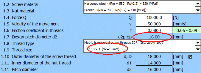
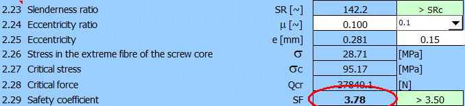
The recommended diameter d2prop and the corresponding screw are selected. And even if the screw satisfies the checks for tension, pressure, compression (thrust), it does not pass the buckling check.
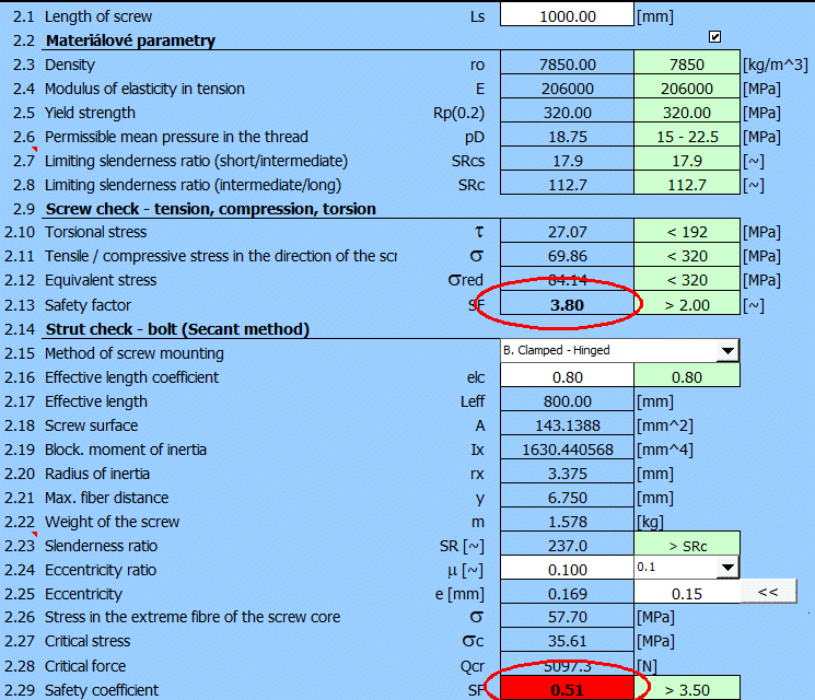
It is therefore necessary to select larger screw diameter.
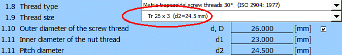
To achieve the adequate buckling safety.
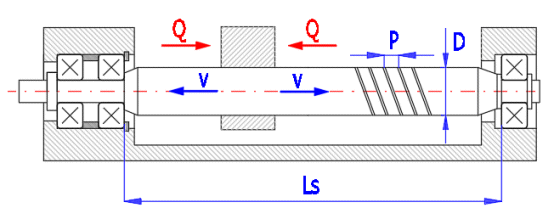
Sample calculation of power screw of an injection device (see the schematic picture).
A. The power screw is subject to torsional or tensile stress.
B. The power screw is subject to a combination of torsion, pressure and buckling stress.
Total load Q = 100,000 [N]
Screw load Q = 50,000 [N]
Feed speed v = 20 [mm/s]
Screw material = hardened steel
Nut material = bronze
Coefficient of friction in threads f = 0.08
Number of thread starts ns = 1
Stroke length Ls = 3,000 [mm]
Used trapezoidal thread (30°, ISO2904: 1997), self-locking is not required.
Based on the recommendation (d2prop[1.7]) , the screw is selected Tr 36 x 10. All strength checks are satisfactory, except the buckling check, which does not occur (no need to consider it).
After selecting a thicker screw (the buckling check must be satisfied), a screw Tr 65 x 4 which also meets the buckling requirements is selected.
Information on options of 2D and 3D graphic outputs and information on cooperation with 2D and 3D CAD systems can be found in the document "Graphic output, CAD systems".
After unchecking the button on the right, you may enter the number of threads that is to be shown on the screw/nut drawing. Pre-filled values are based on the calculation.
Information on setting of calculation parameters and setting of the language can be found in the document "Setting calculations, change the language".
General information on how to modify and extend calculation workbooks is mentioned in the document "Workbook (calculation) modifications".
Závity ISO pro všeobecné
použití - Základní profil - Část 1: Metrické závity
ISO general purpose screw
threads - Basic profile - Part 1: Metric screw threads
Filetages ISO pour usages généraux - Profil de base - Partie 1: Filetages
métriques
ISO-Gewinde allgemeiner Anwendung - Grundprofil - Teil 1: Metrishes Gewinde
Závity ISO pro všeobecné použití - Základní profil - Část 2: Palcové závity
ISO general purpose screw
threads - Basic profile - Part 2: Inch screw threads
Filetages ISO pour usages généraux - Profil de base - Partie 2: Filetages en
inches
ISO Gewinde allgemeiner Anwendung - Grundprofil - Teil 2: Inch-Gewinde
Metrické závity ISO pro všeobecné použití
ISO general purpose metric screw threads — General plan
Filetages metriques ISO pour usages generaux — Vue densemble
Metnsches ISO - Gewinde allgemeiner Anwendung — Ubersicht
Metrické závity ISO pro všeobecné použití - Základní rozměry
ISO general-purpose metric
screw threads - Basic dimensions
Filetages métriques ISO pour usages généraux - Dimensions de base
Metrisches ISO - Gewinde allgemeiner Anwendung - Grundmaße
Metrický lichoběžníkový ISO závit - Základní rozměry
ISO metric trapezoidal screw threads - Basic dimension
Filetagues metriques trapezoidaux ISO - Dimensions de base
Buttress Coarse Thread DIN 513
Unified Inch Screw Threads
ACME Screw Threads
Buttress Inch Screw Threads
7 / 45 Form With 0.6 Pitch Basic Height of Thread Engagement
Joseph E. Shigley, Charles R. Mischke, Richard G. Budynas
R.S.KHURMI AND J.K.GUPTA
26th Edition
ČVUT Praha
Company catalogues: KSK, NSK, THOMSON...
^