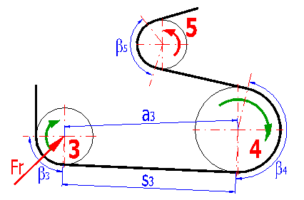
Belt / chain transmission with more sprocket wheels.

Table of Content:

Belt / chain transmission with more sprocket wheels.

The calculation is developed for geometrical designs of belt / chain transmissions with more sprocket wheels. The application provides designs for the following basic tasks.

  1. Calculation of the necessary length of the belt (chain) using known positions and diameters of sprocket wheels
  2. Achieving the desired (table) length of the belt / chain using a change in the position of the selected sprocket wheel.
  3. Calculation of geometry (angles of wrapping, numbers of teeth in engagement, axis distances, etc.)
  4. Calculation of the radial force acting on the sprocket wheel axis.

The application works withe 2D CAD systems.


User interface

 User interface.


Download

 Download.


Purchase, Price list

 Purchase, Price list.
 

Control, structure and syntax of calculations.

Information on the syntax and control of the calculation can be found in the document "Control, structure and syntax of calculations".

Information on the project.

Information on the purpose, use and control of the paragraph "Information on the project" can be found in the document  "Information on the project".

Process of calculation.

  1. Select units and the type of calculations (belt / chain) and fill in the desired global transmission parameters (spacing, power, speed). Paragraph [1.0]
  2. Fill in dimensional units in the table of sprocket wheels (co-ordinates of wheels X, Y, numbers of teeth, switcher outer/inner side of the wheel) and press the button "Calculation". Paragraph [2.0]
  3. Execute additional calculations of the desired length of belt / chain. Paragraph [3.0]

Basic input values. [1]

Define basic parameters of the calculation in this paragraph.

1.1 Units of calculation.

In the selective list, select the desired system of units of the calculation. All values will be recalculated immediately after switching to other units.

1.2 Type of calculation.

Select here whether the calculation has to be executed for a belt or for a chain.

Warning: Calculations of the pitch diameter of the pulley / sprocket wheel for the belt / chain. Do not forget to specify the type of calculation.

1.3 Pitch - toothed belt / chain.

Enter the pitch of teeth of the belt/ chain links in the input field. The selective list to the right of the input field includes pitches of commonly used toothed belts ( chains. The value selected in the list is transferred automatically to the input field.

1.4 Transferred power.

Enter the power transferred by the transmission (the first, driving sprocket wheel).

1.5 Speed of the driving sprocket wheel.

Enter the speed of the first (driving) sprocket wheel - the wheel marked by the digit 1.

1.6 Belt / chain slack side tensions in % of the effective pulling force.

The pulling force is calculated according to the formula F=Mk / R (ratio of the torsional moment and radius of the first pulley). The force in the relieved part of the belt can be chosen as follows:

Belt transmission

Chain transmission

A chain transmission is not usually prestressed. Therefore, use the value 0%.

Calculation table / Calculation. [2]

The following rules are defined for the calculation:

The paragraph includes a calculation table and a drawing (side view) of the designed transmission. Enter co-ordinates of centres of all wheels in the table (columns C,D), the numbers of teeth of each wheel (column E) and specify whether the belt /chain has to circulate around the outer (disabled) or inner (enabled) side of the wheel (column B).

If you also wish to solve the force conditions, enter for each pulley the withdrawn power as a percent of the power demand of the first pulley (column G). The button "Calculation of the transmission" [2.2] initiates the calculation.

Hint: The drawing can also be used for modification of co-ordinates. Click on the centre mark of any pulley and with the mouse button pressed down, shift the centre mark to a new position. Co-ordinates of the centre are changed in the table as well.

2.1 Coordinates and dimensions.

Calculation table.

It includes the following columns.

  1. Order number of the sprocket wheel.
  2. The check mark button specifying whether the belt /chain circulates around the outer / inner side of the sprocket wheel.
  3. X-co-ordinate of the sprocket wheel centre.
  4. Y-co-ordinate of the sprocket wheel centre.
  5. Number of teeth of the sprocket wheel.
  6. The pitch diameter of the sprocket wheel - is calculated additionally using the pitch and number of teeth. It is necessary for the calculation. If you need to enter it directly (e.g. in case of calculation of a flat belt), rewrite the formula in the cell using the desired value.
  7. Loading of the sprocket wheel as a percent of the withdrawn power demand (of wheel no. 1).
  8. Speed of the sprocket wheel.
  9. The angle of wrapping of the sprocket wheel.
  10. Number of teeth in engagement (low number of teeth in engagement makes the parameters of the transmission significantly worse). More detailed information can be found in the calculation of the toothed belt or chain.
  11. Radial force Fr acting on the sprocket wheel axis.
  12. Axis distance of sprocket wheels (from the actual wheel to the following one).
  13. The length of the belt /chain strand (from the actual wheel to the following one).

The illustration shows the outer side marked by a green arrow of rotation, the inner side is provided with a red arrow.

Warning: The calculation uploads rows of the table, beginning with the first row, as long as it meets the row which includes the zero pitch diameter of a sprocket wheel (column F). Other rows are ignored in the calculation.

Drawing of the pulley

Axes X and Y shows dimensions in actual units (mm / in) . The driven sprocket wheel no. 1 is marked red.

2.2 Calculation of the transmission

Pressing the button initiates calculations.

Calculation of the length of the belt / chain. [3]

The following calculation of the table of wheels gives the total length of the belt / chain [3.1]. However, in most cases we need to use belts of standardized length or chains with a number of links which is equal to an integer. In this part we can enter the desired number of teeth of the belt or links of the chain and change co-ordinates of the selected sprocket wheel to achieve the desired length of the belt / chain.

3.1 Total length of the belt / chain.

The length of the belt / chain which is necessary for the designed transmission.

3.2 Number of teeth / chain links.

The value gives the actual number of teeth / links of the calculated belt / chain. It is expressed as a real number (with a decimal part).

3.3 Desired number of teeth / chain links.

In most cases there is available a series of standardized lengths of belts and a series of chains with numbers of links equal to integers. Enter the desired number of teeth of the belt / chain in this field. If the field next to the input cell is provided with a check mark (enabled), the desired value is filled in automatically with a value equal to the whole part of the actual number of teeth of the belt / links of the chain from row 3.2

3.4 Free sprocket wheel / direction.

To calculate a system of wheels to find the desired length of the belt / chain, it is necessary to specify which wheel will be shifted. For this purpose there is available this selective list, which includes numbers of wheels and the direction (X-horizontal or Y-vertical) in which the wheel will be shifted.

3.5 Calculation of a new position of the slackened wheel.

Press the button "Calculation". If the task has a solution, the slackened wheel is shifted to a new position so that the desired length of the belt / chain is obtained.

Warning: An incorrect geometrical requirement (e.g. big change in the length of the belt together with incorrect slackening of the wheel may lead to a task which has no solution. In such cases, modify the entered data.

Graphic output, CAD systems.

Information on options of 2D and 3D graphic outputs and information on cooperation with 2D and 3D CAD systems can be found in the document "Graphic output, CAD systems".

Supplements - This calculation:

Using this calculation, you can make a drawing of the arrangement of the wheels in a front view. You can make a drawing of pitch circles or pitch circles including contour circles.

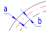
4.3, 4.4 Overlap.

Set the overlap of contour circles as shown in the illustration. If the overlap is set to zero, the respective contour circle will not be drawn.
Setting calculations, change the language.

Information on setting of calculation parameters and setting of the language can be found in the document "Setting calculations, change the language".

Workbook modifications (calculation).

General information on how to modify and extend calculation workbooks is mentioned in the document "Workbook (calculation) modifications".

Supplements - This calculation:

Calculation of a flat belt

The calculation is designed for toothed belts / chains. If you need to design e.g. flat belts, follow the procedure below:


^