This workbook includes two auxiliary calculations to calculations of gearing.
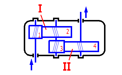
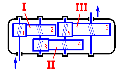
This part enables to distribute the total transmission ratio to individual pairs of gears to optimize some of parameters of a multi-reduction gearbox. The calculation is designed for two- and three-speed gearboxes with spur gears and classical arrangement (see Fig. 1 and 2). The desired gear ratio i1,4(i1,6) is the input parameter, the transmission ratio for individual pairs of gears i1,2 a i3,4 (i5,6) is the output of the calculation.
The optimized parameters are affected by a number of factors (type of the construction, materials, design, etc.). In case of a more complex design it is good to consider these values as the primary input and improve the designed parameters if necessary using some advanced methods (CAD systems, simulation, etc.).
Enter the desired total transmission ratio. This input value is common for double and triple reduction gearboxes. The permissible input value is in the range from 0.001 to 100000.
Immediately after change of the input value the results are displayed - transmission ratio of the first (i1,2), second (i3,4) or third (i5,6) gearing resp., designed for the minimum value of the parameter:


Finding of a combination of the number of teeth of individual gears (it may also be a worm, toothed belt or chain) to approximate the resulting transmission ratio as close to the desired one as possible is a frequent task when designing a synchronous gearing. This task can be resolved using this supplement for single reduction [2], double reduction [3] and triple reduction [4] gearing.
Procedure of calculation. A transmission ratio [2.1] and limiting conditions of a minimum [2.2] and maximum [2.3] number of teeth are desired. After entering of these parameters press the button "Calculation" to start the calculation. The design procedure is indicated in the displayed index. Results of the solution are given in the table [2.4].
Input of the calculation. A total transmission ratio [3.1] is desired and the distribution of this transmission ratio between the first [3.2] and second [3.3] gearing (i3,4 is calculated automatically after entering i1,2). It is also possible to use automatic distribution of the total transmission ratio (see the previous supplement [1]) by selection of the desired parameter from the list [3.4]. Automatic distribution can be activated by enabling of the box on the right to the list of parameters.
Further enter limiting conditions of the minimum and maximum number of teeth of first gears of the first and second gearing [3.5,3.6].
After entering of these parameters press the button "Calculation" to start the calculation. The design procedure is indicated in the displayed index.
Results of the solution are given in the table [3.7].
Input of the calculation. A total transmission ratio [4.1] is desired and the distribution of this transmission ratio between the first [4.2], second [4.3] and third [4.4] gearing (i5,6 is calculated automatically after entering of i1,2 and i3,4). It is also possible to use automatic distribution of the total transmission ratio (see the previous supplement [1]) by selection of the desired parameter from the list [4.5]. Automatic distribution can be activated by enabling of the box on the right to the list of parameters.
Further it is necessary to enter limiting conditions of the minimum and maximum number of teeth of first gears of the first, second and third gearing [4.6,4.7,4.8].
After entering of these parameters press the button "Calculation" to start the calculation. The design procedure is indicated in the displayed index.
Results of the solution are given in the table. [4.9]
Calculation input: The required values are the overall transmission ratio [5.1], gear number [5.2], the number of teeth that will be added to the number of the pinion teeth [5.3], and the number of results listed in the table of results [5.14] (see the “Data“ list for a complete list of results).
Furthermore, it is necessary to enter the transmission ratio of individual gearings on the lines [5.5] to [5.12] and the minimum number of the pinion teeth for the specific gearing. When selecting the number of transmission ratios [5.2], the total transmission ratio is automatically split among all the gear wheels used.
For unused gear sets, the ratio 1.0 is used. The last (final) item i17,18 is calculated based on the previous requirements.
The calculation considers all the pinion tooth combinations (+z) and calculated numbers of the wheel teeth (based on the specified transmission ratio for the specific gear).
After setting the parameters, press the "Calculate" button to start the calculation. The solution progress is shown by a displayed indicator.
The results are shown in the table [5.14] and the 10 best results 10 are shown in the table [5.15].
The table of results includes ten best results (rows) of combinations of teeth of individual gears, whose resulting total transmission ratio is the closest to the desired one. Individual columns contain from left to right:
^