The calculation is designed for geometric designs and checks of bevel and
hypoid gear with straight, oblique and curved teeth according the ISO 23590
The programme gives
solutions to the following tasks:
Preliminary design of the gear size
Detail geometrical design for gear:
- Straight
- Oblique
- Spiral
- Zerol
- Hypoid (Gleason, Oerlikon, Klingelnberg)
Automatic design of a transmission with the minimum number of input requirements.
The calculations use procedures, algorithms and data from ISO 23509 and related standards AGMA ISO 23509 : A, ANSI, ISO, DIN, BS and specialized literature.
User interface.
Download.
Purchase, Price list.
Information on the syntax and control of the calculation can be found in the document "Control, structure and syntax of calculations".
Information on the purpose, use and control of the paragraph "Information on the project" can be found in the document "Information on the project".
Estimation is for a gear with a shaft angle of 90°. For other axis angles, the estimation must be corrected.
Pinion torque is a convenient criterion for approximate rating of bevel gears, requiring conversion from power to torque by the relation:
T1 = 9550 * P / n1
where:
T1 ... pinion torque [N*m]
P ..... power [kW]
n1 ... pinion speed [/min]
Pinion outer pitch diameter versus pinion torque, transmission ratio, material, gear type, load type...:
Pitting resistance
de1 = (0 + 15 * T1^0.325) / (u^0.35) * KM * SZF * PFG [mm]
Bending strength
For T1 < 5000
[N*m]
de1 = (0 + 14 * T1^0.35) / (u^0.5) *
LTF * SZF
[mm]
For T1 >=5000
[N*m]
de1 = (0 + 14 * T1^0.35) / (u^0.5) * u^0.14 *
(T1/5000)^0.1 *
LTF * SZF
[mm]
where:
de1 ... Pinion outer pitch diameter
[mm]
T1 .... Pinion torque
[N*m]
u ...... Transmission ratio
KM .... Material factor
SZF.... Straight and zerol bevel factor
PFG ... Precision-finished gears
LTF ... Load type factor
For hypoid gears:
deplm1 = de1 - a / u
where:
deplm1... Preliminary hypoid pinion pitch diameter [mm]
de1 ........ Pinion outer pitch diameter
[mm] (larger value from previous calculation)
a ............ Hypoid offset [mm]
u ........... Transmission ratio
All used geometry formulas can be found in ISO 23509. Below is the geometry nomenclature.
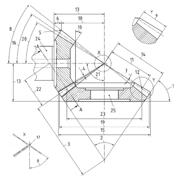
back angle
back cone angle
back cone distance
clearance - c
crown point
crown to back
dedendum angle - Thetaf1, Thetaf2
face angle - deltaa1, deltaa2
face width - b
front angle
mean cone distance - Rm
mean point
mounting distance
outer cone distance - Re
outside diameter - dae1, dae2
pitch angle - delta1, delta2
pitch cone apex
crown to crossing point - txo1, txo2
outer pitch diameter - de1, de2
root angle - deltaf1, deltaf2
shaft angle - Sigma
equivalent pitch radius
mean pitch diameter - dm1, dm2
pinion
wheel
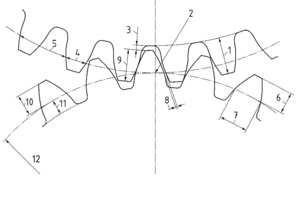
whole depth - hm
pitch point
clearance - c
circular thickness
circular pitch
chordal addendum
chordal thickness
backlash
working depth - hmw
addendum - ham
dedendum - hfm
equivalent pitch radius
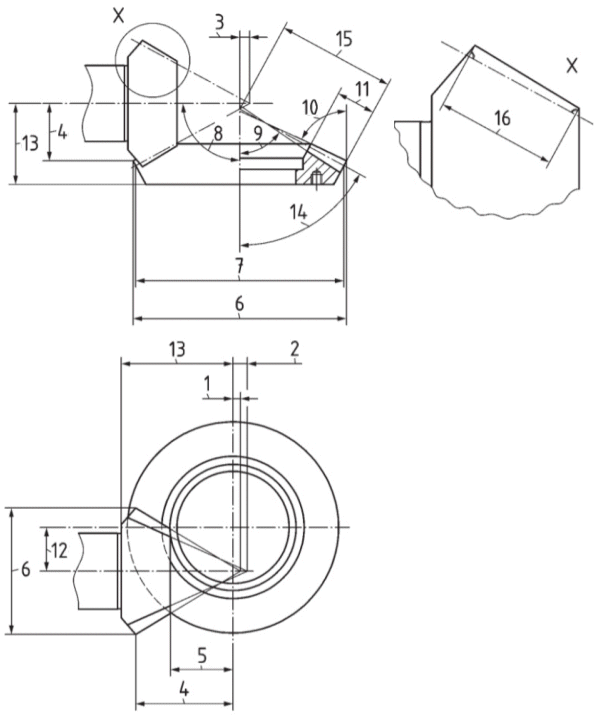
face apex beyond crossing point - tzF1
root apex beyond crossing point - tzR1
pitch apex beyond crossing point - tz1
crown to crossing point - txo1, txo2
front crown to crossing point - txi1
outside diameter - dae1, dae2
outer pitch diameter - de1, de2
shaft angle - Sigma
root angle - deltaf1, deltaf2
face angle of blank - deltaa1, deltaa2
wheel face width - b2
hypoid offset - a
mounting distance
pitch angle - delta2
outer cone distance - Re
pinion face width - b1
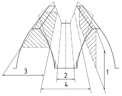
depth
slot width
thickness
space width
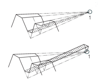
pitch cone apex
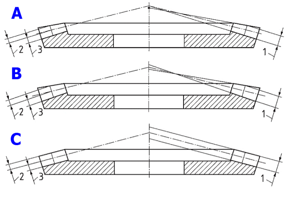
A. Standard depth taper
B. Constant and modified slot width
C. Uniform depth
mean whole depth
mean addendum
mean dedendum
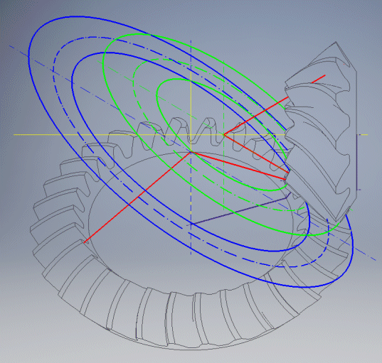
Two basic principles of machining are primarily used for the calculation and generation of the 3D models of the gear wheels.
The curvature is an extended epicycloid (locus), which is created by rolling the tool on the basic circle of the epicycloid.
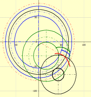
The curvature radius is equal to the radius of the tool.
|
Symbol |
Symbol |
Description |
Method 0 |
Method 1 |
Method 2 |
Method 3 |
|
Sigma |
S |
Shaft angle |
X |
X |
X |
X |
|
a |
a |
Hypoid offset |
0.0 |
X |
X |
X |
|
z1, z2 |
z1, z2 |
Number of teeth |
X |
X |
X |
X |
|
dm2 |
dm2 |
Mean pitch diameter of wheel |
- |
- |
X |
- |
|
de2 |
de2 |
Outer pitch diameter of wheel |
X |
X |
- |
X |
|
b2 |
b2 |
Wheel face width |
X |
X |
X |
X |
|
betam1 |
bm1 |
Mean spiral angle of pinion |
- |
X |
- |
- |
|
betam2 |
bm2 |
Mean spiral angle of wheel |
X |
- |
X |
X |
|
rc0 |
rc0 |
Cutter radius |
X |
X |
X |
X |
|
z0 |
z0 |
Number of
blade groups |
X |
X |
X |
X |
This calculation is intended primarily for geometry design. The calculation or a gear size design, respectively, is only indicative and needs to be checked with respect to the relevant standard or the documentation supplied by the manufacturer of the specific machining centre.
Enter the power and operating parameters of transmission (transmitted power, rotation speed, type of gears, material, type of load, ...). [1]
Enter the gear ratio or the number of teeth, respectively; the angle of shaft axes angle; the shaft offset; and the toothing width and angle [2]
Specify the tooth profile parameters. [3]
Based on the type of toothing, select the relevant method of calculation 0, 1, 2, or 3. [4,5,6,7]
Using the relevant method, enter the input geometric parameter or run iteration of the calculation.
Check the results. Use the graphic representation in paragraph [9.0].
If necessary, load the 2D drawing into the 2D CAD system, or generate data for creation of a precision 3D model.
Enter basic input parameters of the designed gearing in this paragraph.
Use the drop-down menu to choose the required system of units for calculation. After the units are switched, all values will immediately be re-calculated automatically.
Enter the power to the driven gear. Usual values are in the range 2 - 500 kW / 3-700 HP, in extreme cases up to 4000 kW / 6000 HP.
Enter the speed of the driven gear. Extreme speed can reach 50 000 rpm. The speed of the driven gear is calculated using the number of teeth of both gears.
This is the result of the calculation and cannot be entered.
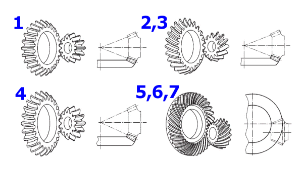
This calculation allows users to solve a choice of gearing types. Select the type of toothing from the list. By making this selection, you also select a range of coefficients which affect the estimate of the gear assembly size and the coefficients for geometry calculations.
Standard straight toothing - Methode 0
Standard oblique toothing - Methode 0
Spiral bevel gears (non hypoids) - Methode 0
Zerol bevels - Methode 0
Hypoid spiral bevel gears (Gleason) - Methode 1
Hypoid spiral bevel gears (Oerlikon) - Methode 2
Hypoid spiral bevel gears (Klingelnberg) - Methode 3
For materials other than case-hardened steel at 55 minimum HRC, the pinion outer pitch diameter, as given in Figure B.2 ISO 23509, is to be multiplied by the material factor KM
"Precision finish", refers to a machine finishing operation which includes grinding, skiving and hard cut finishing.
Statically loaded gears should be designed for bending strength rather than pitting resistance For statically loaded gears which are subject to vibration, the pinion outer pitch diameter, as given in Figure B.2 ISO 23509, is to be multiplied by 0,70. For statically loaded gears which are not subject to vibration, the pinion outer pitch diameter, as given in Figure B.2, B.3 ISO 23509, is to be multiplied by 0,60.
It only affects the design of the backlash.
In this paragraph, select the gear ratio, numbers of teeth, angle of axes, offset of axes, etc. Then you obtain a preliminary design of the size and shape of toothing.
- The entered number of teeth and the angle of axes are used for all the
methods of the geometry calculations.
- The diameters, the axes offsets, the width of toothing, and the angle of
toothing are then offered in a specific paragraph (Methods 0 to 3) as the
recommended values (minimum and maximum).
The optimum transmission ratio varies in the range 1-5. In extreme cases this ratio can reach up to 10. The transmission ratio can be entered in the left input field using the keyboard. The right pop-up list contains recommended values of the transmission ratio and when selecting a value from this list, the chosen value is added to the field on the left automatically.
The recommended (and minimum) number of pinion teeth is based on the ISO 23590 standard. The recommended number of the gear teeth is then calculated based on the gear ratio entered on the previous line.
Enter the number of pinion teeth. The number of gear teeth is calculated based on the required gear ratio [2.1]. After checking the checkbox on the right, it is possible to enter the number of the gear teeth directly.
As the actual transmission ratio is the ratio of the number of teeth of both gears (integers), the actual transmission ratio will be mostly different from the desired (entered) one. The value of the "Actual transmission ratio" is displayed on the left; the percentage deviation from the desired transmission ratio is displayed on the right. This deviation for the transmission ratio should be in the range:
i = 1 to 4.5 ........... 2.5%
i is greater than 4.5... 4.0%
Enter the angle of axes of individual wheels (mostly 90°). The calculation also enables options of other values. The case when the angle of the pitch cone exceeds 90° is indicated by a red cell. (This creates conical gearing that cannot be produced on usual machines).
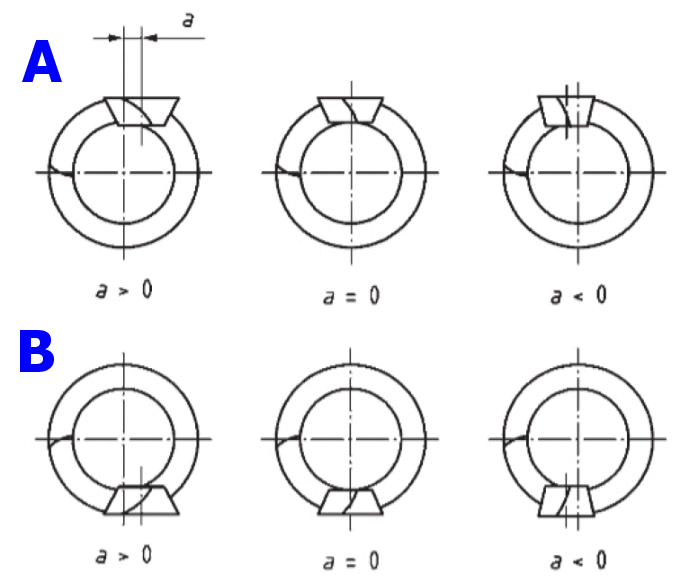
In most cases, the hypoid offset is determined by the application. Pinion offset is designated as being positive or negative.
Picture illustrates positive and negative pinion offsets as seen from the wheel apex.
A. Left-hand pinion mated with right-hand wheel
B. Right-hand pinion mated with left-hand wheel
It is recommended that positive pinion offset be used because of the increasing diameter of the pinion, higher face contact ratio, pitting and bending load capacity. ln general, due to lengthwise sliding, the offset should not exceed 25 % of the wheel outer pitch diameter and, for heavy-duty applications, it should be limited to 12,5 % of the wheel pitch diameter.
Based on power and geometry inputs, the outer pitch diameter is estimated.
Since tooling for bevel gears is not standardized according to module, it is not necessary that the module be an integer. However, it is possible in calculation to calculate the wheel size according to the required module.
After clearing the button the value of the toothing width can be entered.
Ticking the button automatically selects the maximum value.
Generally, the face width is 30% of the cone distance Re2 or 10*met, whichever
is less. However, design parameters may require values to be larger or smaller.
For zerol bevel gears, the face width should be multiplied by 0.83 and should
not exceed 25 % of the Re2.
For shaft angles less than 90° the face width larger than given may be used. For
shaft angles greater than 90° the face width smaller than given should be used.
The hypoid pinion face width is generally greater than the face width of the
wheel.
Common design practice suggests that the spiral angle be selected to give a face contact ratio of approximately 2.0. For high-speed applications and maximum smoothness and quietness, face contact ratios greater than 2.0 are suggested, but face contact ratios less than 2.0 are allowed.
For hypoid sets, the pinion spiral angle may be calculated using Formula:
betam1 = 25 + (z2 / z1)^0.2 + 90 * a / de2
where:
z1, z2 .... Number of teeth
a ........... Hypoid offset [mm]
de2 ....... Gear outer pitch diameter [mm]
Enter basic input parameters for tooth profile in this paragraph.
There are three normal pressure angles that are to be considered.
- Nominal design pressure angle alfad, is the start value for the calculation.
It may be half of the sum of pressure angles or different on drive and coast
side.
- Generated pressure angle alfan, is the pressure angle of the generating gear;
alfan can be found on the tooth flank in the mean normal section.
- Effective pressure angle, alfae, is a calculated value.
The most commonly used design pressure angle for bevel gears is 20°. This
pressure angle affects the gear design in a number of ways. Lower generated
pressure angles increase the transverse contact ratio, reduce the axial and
separating forces and increase the toplands and slot widths. The converse is
true for higher pressure angles. Based on the requirements of the application,
the engineer may decide to choose higher or lower design pressure angles. Lower
effective pressure angles increase the risk of undercut.
For hypoid gears, it could be reasonable to have unequal generated pressure
angles on the coast and drive sides, in order to balance the mesh conditions. If
full balance of the mesh conditions is recommended, the influence factor of
limit pressure angle, falfalim, is set to "1". Then the limit pressure angle,
alfalim, is added to the design pressure angle alfad, on the drive side and
subtracted on the coast side in order to obtain the generated normal pressure
angle, alfan.
As for bevel (non-hypoid] gears, the limit pressure always is equal to zero, the
nominal design pressure angles have the same values as the generated pressure
angles. If the effective pressure angles have the same values, the mesh
conditions on coast and drive side are equal.
Straight bevels
To avoid undercut, use a nominal design pressure angle of 20° or higher for
pinions with 14 to 16 teeth and 25° for pinions with 12 or 13 teeth.
Zerol bevels
On zero bevels 22.5° and 25° nominal design pressure angles are used for low
tooth numbers, high ratios, or both, to prevent undercut. Use a 22.5° nominal
design pressure angle for pinions with 14 to 16 teeth and a 25° nominal design
pressure angle for pinions with 13 teeth.
Spiral bevels
To avoid undercut a 20° design pressure angle or higher for pinions with 12
teeth or fewer teeth may be used.
Hypoids
To balance the mesh conditions on coast and drive side, the influence factor of
limit pressure angle should be falfalim = “1”. For the use of standard cutting
tools, the value of falfalim may be different from "1". The nominal design
pressure angles 18° or 20° may be used for light-duty drives; higher pressure
angles such as 22.5° and 25° for heavy-duty drives.
Two alternative sets of input data, those used by American Gear Manufacturers Association AGMA - (data type ll) and those used in European Standards - (data type l) be available to calculate one or more of the four design methods shown.
After selecting the type, the related values will also be calculated for the second set of input data and displayed in the right column. The data in the right column are then used for the calculation. In the green column, the recommended values resulting from the previous data (toothing type, gear ratio, number of teeth) are shown.
Recommended values for gearings with the angle of axes 90°:
Gear ratio / xhm1
1..............0.00
1.12..........0.10
1.25..........0.19
1.6............0.27
2...............0.33
2.5............0.38
3...............0.40
4...............0.43
5...............0.44
6...............0.45
In common cases, the addendum factor khap is set to khap = 1.00 and the dedendum factor khfp is set to khfp = 1.25.
In common cases, the addendum factor khap is set to khap = 1.00 and the dedendum factor khfp is set to khfp = 1.25.
Adjust the value of the unit change of the tooth thickness here. Recommended
values for gearings with the angle of axes 90°:
Gear ratio / xsmn
1……………0.0
1.12………0.010
1.25………0.018
1.6…………0.024
2……………0.030
2.5…………0.039
3……………0.048
4……………0.065
5……………0.082
6……………0.100
This factor apportions the working depth between the pinion and wheel addendums. The pinion addendum is usually longer than the wheel addendum, except when the numbers of teeth are equal. Longer addendums are used on the pinion to avoid undercut. Suggested values for shaft angles Sum = 90° for cham are on the right. Other values based on sliding velocity, topland or point width limits, or matching strength between two members, can be used. Clause8 from ISO 23509 gives the limits for the mean addendum factor to prevent undercut on pinion and wheel.
Normally, a depth factor kd = 2.000 is used to calculate mean working depth hmw, but it can be varied to suit design and other requirements. The value on right gives the suggested depth factors based on pinion tooth numbers.
While the clearance is constant along the entire length of the tooth, the calculation is made at mean point. Normally, the value of 0.125 is used for the clearance factor kc, but it can be varied to suit the design and other requirements.
The mean normal circular thickness is calculated at the mean point. Values of kt based on balanced bending stress are on the right. Other values of kt may be used if a different strength balance is desired.
The following paragraphs describe the above-mentioned methods of calculation corresponding to the selected type of toothing [1.5]. Expand the corresponding method and specify the input parameters of toothing. The recommended values based on the draft design (see par. 1.0, 2.0, and 3.0) are shown on the right side. When using the methods 1, 2 and 3, it is usually required to perform an iteration to finish the calculation of the geometric results.
Using the '<<' button located at the beginning of the paragraph on the right [4.1, 5.1, 6.1, 7.1], fill in the values from the preliminary draft (paragraphs [1.0], [2.0], [3.0]).
Choose the value de2 (dm2). It should be larger than the value on the right based on the preliminary design.
Choose the value de2 (dm2). It should be larger than the value on the right based on the preliminary design.
Choose the value b2. It should be smaller than the value on the right, which depends on the input parameters specified in this paragraph.
Choose the value betam2 (betam1). It should be greater than the value on the right side shown in the brackets for achievement of the mesh coefficient eb =2.0, paragraph [2.12]. The permitted range is given in the angle brackets '<...>'.
Select the value a. It should be in the range of values on the right side. It it dependent on the entered input parameters in this paragraph. See paragraph [2.6]
Suggested minimum values of the outer backlash are on the right. It will be noted that the backlash allowance is proportional to the module. Two ranges of values are given: one for ISO accuracy grades 4 to 7, the other for ISO accuracy grades 8 to 12, according to ISO 1328-1. See [1.12]. The brackets contain the recommended mean value.
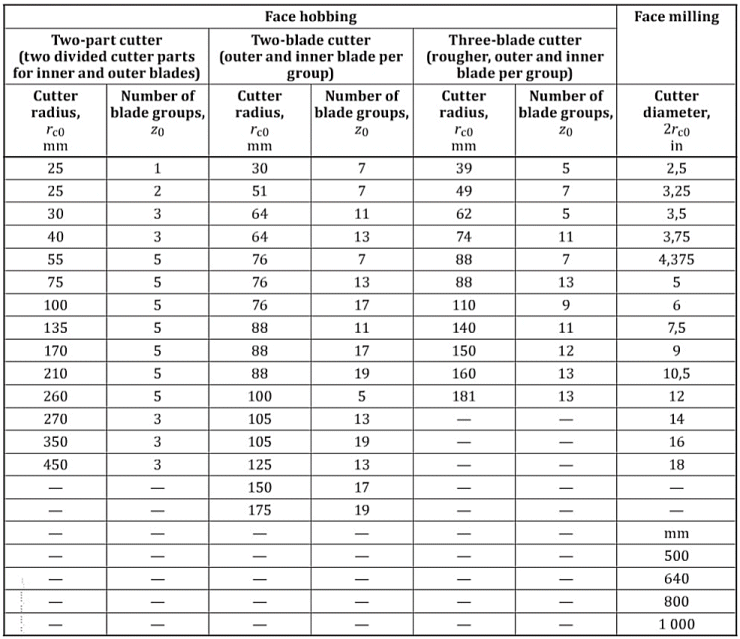
Since bevel gear design and manufacture are functions of the cutter radius and, for face hobbed gears, also the number of blade groups, There is a list of standard cutters. The recommended range is given in the angle brackets '<...>'.
Select the tooth profile that corresponds to the type of toothing and your requirements. After making your selection, the angles Thetaa2 and Thetaf2 will be proposed accordingly, which will be used in the calculation. Upon checking the checkbox, custom values may be entered.
If you need to achieve the exact mmn (met) module, enter the required value and push the "<” button. The de2 (dm2) value will be calculated. In most cases, it will be necessary to run the iteration again and repeat the calculation (Methods 1, 2, and 3).
In loaded gearing there appear some forces that are transferred to the
machine structure. Knowledge of these forces is fundamental for correct
dimensioning of the equipment. The orientation of the forces can be seen in the
following illustration. Row
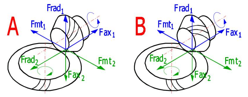
To calculate the forces, use the same method as was used for the geometry solution. The geometrical values obtained from the method selected including the input data (see par. 1 - 3) shall be used for the calculation of forces.
According to the direction of the teeth pitch, right and left wheels are
distinguished. The teeth of wheels in the mesh must have opposite directions of
curving. The gearing as a unit is characterized by the direction of curving of
the pinion teeth.
In case of gearing with oblique and curved teeth, a rotary movement mostly in
one direction is desired. The direction of teeth curving is then chosen to push
the wheels out of the mesh by axial forces (the teeth enter the mesh by their
thicker ends on the outer surface of the wheels).
The illustration shows the direction of the pinion teeth pitch:
A - Left
B - Right
Information on options of 2D and 3D graphic outputs and information on cooperation with 2D and 3D CAD systems can be found in the document "Graphic output, CAD systems".
In addition to the standard 2D output drawing, this calculation also includes ready background data for the creation of a precision 3D model of the bevel, or hypoid gearing suitable for manufacturing, printing, or testing.
1. In the "Output of a 2D drawing into" list, choose the target CAD system (target application) to which the picture should be generated, or a "DXF File" to convert the drawing into a .DXF file.
2. In the "Scale of 2D drawing" list, set up the drawing scale. The drawing is always created in the scale 1:1. The scale allows you to set only certain parameters of the drawing, such as the size of the text or overlapping of the axes.
3. If necessary, set up another control elements as well. Most calculations also include other setting options, which depend on the calculation and type of the plotted object. Explanation of these supplementary options can be found in the help for the respective calculation.
4. Start plotting using the button with the icon of the desired drawing.
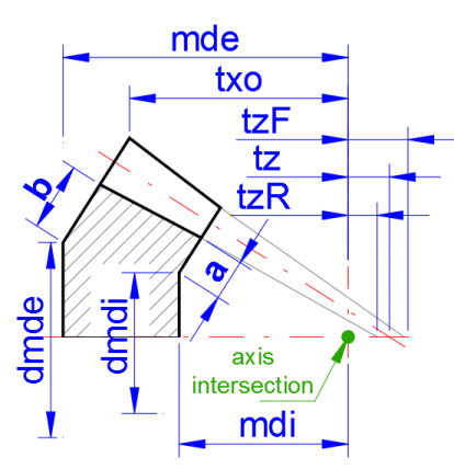
The functional dimensions are based on the calculation. However, in this section you can define the wheel dimensions in a manner that allows them to also meet other requirements. This mainly concerns the assembly dimensions (mdi, mde). After ticking the check box in [9.5], you can enter the preferred gap sizes a, b. Upon changing these values, the parameters of the assembly distance also change (mdi, mde), as do the diameters (dmdi, dmde). On the right side of the calculated values [9.7–9.10], it is possible to enter the required dimension value, and upon pressing the button '<=1' or '<=2' the gap values a, b are adjusted for the pinion or gear wheel such that the mdi, mde, dmdi, and dmde values correspond to the required value.
The mutual relationship of the entered values is clear from the figure.
Locate the text description in the 2D drawing by pressing the button “Draw”.
The text can be edited after the tick off box has been activated.
If it is supported by the respective module for entering models into a 3D CAD
system, the contents of individual rows is entered into user attributes of the
model and these can be used when generating a BOM.
(Details can be found in Help for connection to the respective 3D CAD system.)
A series of calculations (gearing, springs, etc.) enables entering of the respective table with text information on the calculated object into the drawing. The table can be selected from the respective list (in case the calculation enables more types to be entered). Drawing of the table can be activated by pressing the button “Draw a table”.
Defining a 3D model is not a completely trivial issue, and defining the parametric model for an arbitrary CAD system is complicated. For this reason, we have prepared an option to generate the background data for the creation of a precision non-parametric model, in principle for an any 3D CAD system.
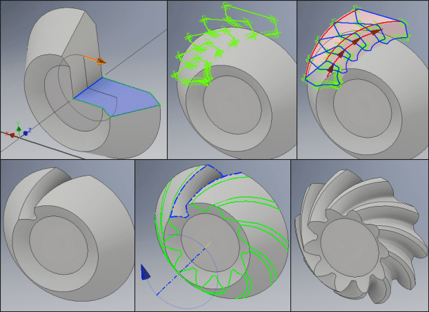
The creation of a precision model thus consists of three simple operations.
Creating the wheel without gearing (simple rotation of the wheel profile).
Downloading the profiles of the gaps between the teeth at defined intervals, their interconnection and deduction of the created volume from the created wheel.
Generating a rotary field of gaps and thereby creating of a precision gear wheel.
General procedure:
Set the output parameters [9.20–9.31] of the generated dimensions suitable for your 3D CAD system (examples and details in the help file and the examples).
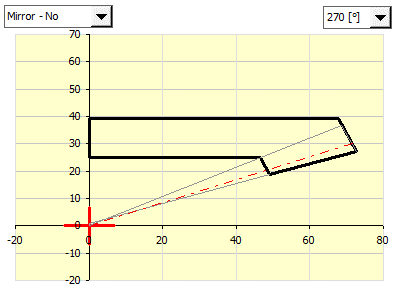
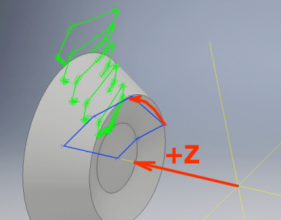
In point [9.33] set the rotation (mirroring) of the wheel profile
chosen in the figure so that upon insertion into your selected surface in your
CAD system, the profile is rotated around the positive z-half-axis.
Generate the profile of the selected wheel (First button).

In the CAD system, insert the profile into the selected plane and create the wheel semi-product by rotating around the z-axis.
Generate the cross sections of the tooth gaps (Second button).

Gradually insert the generated cross sections into the model.
For wheels with spur gearing, two cross sections are sufficient for 1–9.
For wheels with bevels or curved teeth or for hypoid wheels, it is usually
sufficient to use cross sections 1-3-5-7-9.
For higher precision, it is possible to use all 9 cross sections.
Interlink the entered cross sections with the LOFT operation and deduct the created element from the wheel profile.
Create rotary fields around the z-axis from the gap between the teeth (number of copies = number of teeth).
Insert the wheel into the system, and use the dimensions a,
mdi,or mde from [9.7 or 9.8] to locate it correctly.
Some CAD systems may also require the profile paths (Third
Button) to correctly link the profiles.

B: 1.1-1.2; C: 15-25; D: Yes; E: 5; F: No; G: XLSX; [9.22] Wheel profile rotation 270, Mirror No.
Wheel creation: 2D Sketch - XZ plane, import points from xlsx, connect points
by line, rotate profile around z-axis
Tooth creation: 3D Sketch - Import profile points from xlsx, connect points by
curve, close the open profile manually by line, repeat for profiles 1-9, join
B: 1.1-1.2; C: 15-25; D: Yes; E: 5; F: Yes; G: DXF for wheel profile, G:
SLDCRV for profiles and control curves; [9.22]
Tooth creation: 3D Sketch
a)
b) Control curve import (Profile Path) from SLDCRV. Select one or more control
curves.
c) J
B: 1.1-1.2; C: 15-25; D: Yes; E: 5; F: Yes; G: DXF for wheel profile, G: XLSX for profiles and control curves; [9.22] Wheel Profile Rotation 270, Mirror No.
Wheel creation: Open DXF from file xx_Pinion-cone.dxf (Options ...-> Import
2D geometry, Part Sketch, Right (YZ)),
Tooth creation:
a) Surfacing => Curve by table, importing profiles from XLSX (Parameters: Curve
Fit = Smoothing Off, Curve End Conditions = Closed, Natural), repeat for
sections 1-9.
b) Home => Lofted Cutout
B: 1.1-1.2; C: 15-25; D: Yes; E: 5; F: Yes; G: IBL [9.22] Wheel Profile Rotation 270, Mirror No.
Tooth creation:
a) Create a blend element from the xx_All_InOne.ibl file to create a single
dental space.
b) Creating a rotary field by multiplying the blend element.
To generate curves, it is necessary to use a third-party tool capable of
reading the points and connecting them into a curve. Catia does not allow direct
reading of the curve points.
It is naturally possible to manually copy the individual cross-sections from the
generated files to the definition tables of the curves.
Choose whether the data should be generated for the pinion or gear wheel. The selection of the type of orientation of the gearing applies to the pinion; the wheel is oriented in the opposite direction.
It is possible to set the value at 01–10. When saving the files necessary for the creation of the 3D model, a name is offered by default, for instance, '01_Pinion'. This is suitable, for instance, for the creation of various versions of the model.
If the save remark switch setting is 'Yes', a text file containing the complete input parameters of the gearing is generated together with the profiles.
Set the rotation (mirroring) of the wheel profile (First button) to be rotated around the z-axis. By rotating, it is possible to correctly position the wheel profile in the coordinate system of your CAD system. A graphic representation is in figure [9.34].
Inventor - 270
Solidworks - 90
Creo - 270
The radius is given in multiples of the module. For hypoid gearing and gearing with larger angle of contact alpha, it is suitable to start with a value of 0.1 and increase this value according to requirements after checking the model. DIN uses the values 0.25 to 0.38, ANSI uses the value 0.3. In principle, it is possible to select an arbitrary value in the approximate range of 0.02 to 0.4.
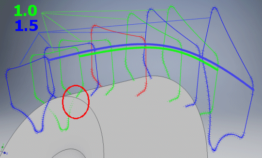
This states the increase of the gap between the profiles, which forms the volume deducted from the wheel base (the face width must be exceeded). In normal cases, 1.1 is suitable; for a non-standard profile it is possible to increase this to 2.0.
It states how many points will be generated to define the tooth side curve. Normally, the suitable value is 20. For special cases (limitations of the CAD system, precision, etc.) it is possible to use values 12 to 200.
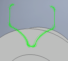
Above the generated profile of the gap between the teeth, another piece is added, which can be suitable for better selection of the curves, or whose presence is necessary to correctly interpret the curves.
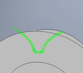
It states the number of points to be used for the curvature of the connection and end of the superstructure. In most cases, five is sufficient.
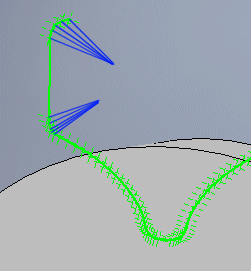
Some CAD systems require a closed profile, while some require a profile that is manually opened or closed. The switch connects/disconnects the first and last points of the profile.

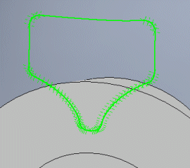
Various CAD systems support importing points that form the curves in various formats. The following formats are available:
It inserts a small circle into each point of the curve. Suitable in a case where the CAD system is capable of downloading only the DXF format and it is necessary to create a profile manually, point by point.
The program is capable of generating individual cross sections that define the intermediate tooth gap (see above). The number of the cross sections is automatically added to the file name. In most cases, it is best to generate all 9 cross sections in a single step by selecting 'All'. The cross sections are generated and numbered from the outer diameter.
The selection 'All in one' allows the generation of all cross sections in one file of format:
StartLoft
StartCurve
- first shape x,y,z
EndCurve
StartCurve
- second shape x,y,z
......
EndCurve
EndLoft
End
Closed
Arclength
Begin section
Begin curve
- first shape x,y,z
Begin section
Begin curve
- second shape x,y,z
......
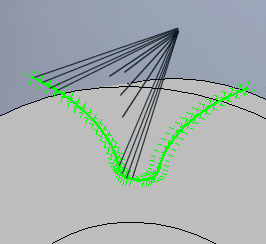
Some CAD systems require the directrix (directrices) in addition to the connected profiles. Enter the sequence number of the curve and press the button.

The numbering of the directrices is shown in the figure and passes through the corresponding point of the profiles.
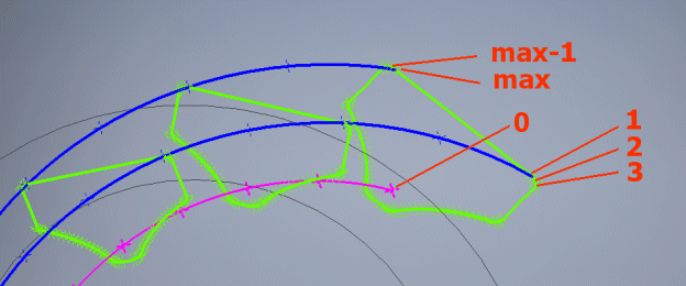
If you enter 0, a curve is generated that lies on the surface of the pitch cone and runs through the centre of each profile.
The parameters of the gearing that fully define the geometry and important dimensions are entered in short form in the line.
The graph in the top left shows how the wheel profile will be generated. It is possible to turn and mirror it in such a manner that it suits the requirement (after input to the CAD system) that the wheel profile must be rotated according to the positive z-half-axis. The individual profiles of the inter-tooth gaps are defined in relation to this half-axis. Settings can be changed in the selection lists in the graph.


The figure shows the sequence of steps necessary to generate the wheel.
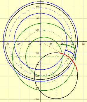
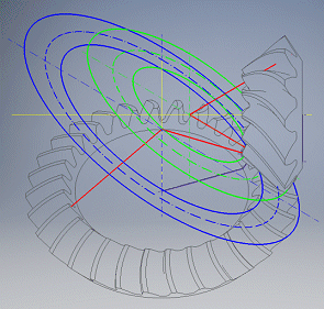
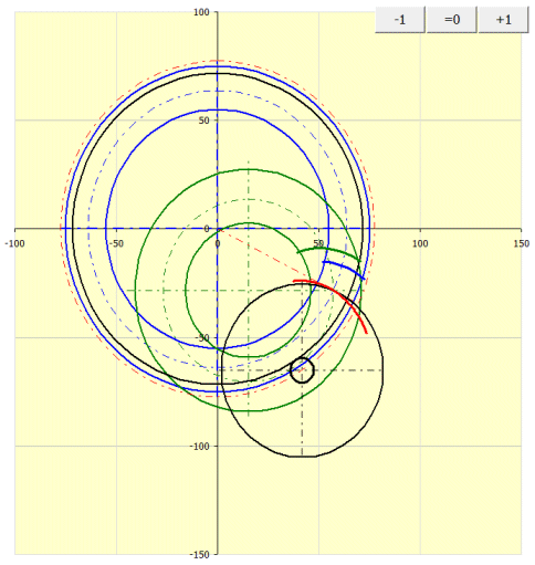
The graph shows the geometry of contact curves of the teeth in the pitch plane.
The wheel and the gear tooth curve path are shown in blue.
The pinion and the pinion tooth curve path are shown in green.
Black is used to indicate the machine tool, rolling circle.
Red is used to indicate the creative path of the tool that is shared by the
pinion and wheel.
The button '=0' is used to set the gearing to the zero position. The buttons '+' and '-' are used to turn the wheel and pinion in the gear ratio.
For offset of the axes a=0 (method 0), the pinion and wheel merge into a green circle.
Information on setting of calculation parameters and setting of the language can be found in the document "Setting calculations, change the language".
General information on how to modify and extend calculation workbooks is mentioned in the document "Workbook (calculation) modifications".
- Bevel and hypoid gear geometry
- Géométrie des engrenages coniques et hypoides
- Geometrie kuželového a hypoidního ozubení
ISO 23509:2016 specifies the geometry of bevel gears. The term bevel gears is used to mean straight, spiral, zerol bevel and hypoid gear designs. If the text pertains to one or more, but not all, of these, the specific forms are identified. ISO 23509:2016 is intended for use by an experienced gear designer capable of selecting reasonable values for the factors based on his knowledge and background. It is not intended for use by the engineering public at large.
BEVEL AND HYPOID GEAR GEOMETRY
American Gear Manufacturers Association
Equivalent Standard(s) Relationship - ISO 23509 : 2016 Identical
CALCULATION OF LOAD CAPACITY OF BEVEL GEARS - PART 1: INTRODUCTION AND GENERAL INFLUENCE FACTORS
CALCULATION OF LOAD CAPACITY OF BEVEL GEARS - PART 3: CALCULATION OF TOOTH ROOT STRENGTH
CALCULATION OF LOAD CAPACITY OF BEVEL GEARS - PART 2: CALCULATION OF SURFACE DURABILITY (PITTING)
^