The calculation is designed for geometric and strength designs and checks of tapered toothing with straight, oblique and curved teeth. The programme gives solutions to the following tasks:
The calculations use procedures, algorithms and data from standards ANSI, ISO, DIN, BS and specialized literature.
List of standards: DIN 3971, DIN 3991 Kegelradern 1-4, ISO 6336 1-3,
DIN 3965 Toleranzen für Kegelradverzahnungen 1-4,
ISO 1328, DIN 3990,
![]()
User interface.
![]()
Download.
![]()
Purchase, Price list.
Information on the syntax and control of the calculation can be found in the document "Control, structure and syntax of calculations".
Information on the purpose, use and control of the paragraph "Information on the project" can be found in the document "Information on the project".
Rolling gears with tapered wheels can be used for the formation of kinematic and force bound between concurrent shafts (mostly at angles of axes Σ=90°). According to the course of the teeth wheels with straight, oblique and curved teeth are distinguished. Compared with cylindrical wheels, tapered wheel are more demanding in view of production and installation. Production of such toothing needs specialised tools and machines and it is more difficult to achieve the desired level of accuracy. In case of on-the-fly-seating the danger of deformation is increased; this also means worse mesh conditions (above all, for wheels with straight teeth). Wheels with oblique and curved teeth are used for higher speeds, higher loads and higher gear ratios (up to i=10).
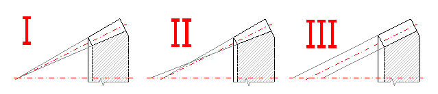
Geometry of a gearing consists of a pair of truncated cones (foot and head cones) and a pitch cone between them.
Type I – Head and foot conical surfaces have a common top.
Type II – The foot cone top is shifted to create a constant width of the teeth
gap.
Type III – Constant height of teeth. Surfaces of all cones are parallel.
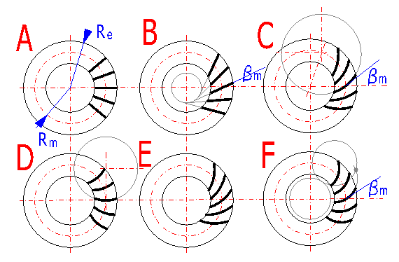
A – Straight teeth, B – Oblique teeth, C – Circular teeth, D – Circular teeth
("Zerol"),
E – Paloid teeth, F – Eloid teeth
|
Guiding straight line |
Name | Height of the tooth | Dimensions, notes |
| 1.
Radial straight line |
Straight toothing | variable | met-standardised,
a=20°,
15°, 14.5°, 17.5°, b=bm=0° Gearings with low requirements, higher noise level, lower circumference speeds v=2-3 m/sec (6-10ft/sec). |
| 2. Oblique straight line |
Oblique toothing | variable | met-standardised,
a=20°,
15°, 14.5°, 17.5°, b=bm=20°-40°
(po 5°) Higher circumference speeds, lower noise level, higher loading, longer life, lower sensitivity to inaccuracies and deformations, higher gear ratio can be used (<10) |
| 3. Circular arch |
Gleason (USA) |
variable; heat, pitch and foot cones do not have any common top | mmn-standardised,
amn=20°,
17.5°, 14.5°, bm=30°-45°
(mostly 35°) |
| Gleason-Zerol (USA) |
mmn-standardised, amn=20°, 17.5°, 14.5°, bm=0° | ||
|
Modul-Kurvex (Germany) |
constant | mmn-standardised, amn=20°, 17.5°, 14.5°, bm=25°-45° | |
| 4.
Evolvent (paloid) |
Paloid toothing Klingelnberg (Germany) |
constant | mmn-standardised, amn=20°, 17.5°, bm=30°-38° |
| 5. Epicycloid |
Eloid toothing Oerlikon-Spiromatic |
constant | mmn-standardised, amn=17.5°, bm=30°-50° |
|
Cyclopaloid toothing Klingelnberg (Ger.) |
constant | mmn-standardised, amn=20°, 17.5°, bm=0°-45° |
Geared transmissions can be divided into:
Power gearing - In case of gearing designed, above all, for a power transmission and transformation, it is necessary to perform a strength design/check (for example, drives of machines, industrial gearboxes, etc.).
Non-power gearing - In case of gearing with minimum transferred torsional moment with respect to the size of the gears, it is not necessary to perform any strength design/check (for example, instruments, regulation devices, etc.).
The design of the gearing cannot be solved directly and allows considerable freedom in options of diameter and width parameters of toothed wheels. Therefore it is necessary to proceed iteratively and make the design more and more exact and tune the monitored parameters.
This procedure gives a quick view of the parameters of the designed gearing. Although gearing designed in this way can be used, step-by-step optimising of several parameters can substantially improve the properties of the designed gearing. Proceed in the design as follows:
Before optimising parameters, first execute the "Fast (orientation) design", as described above, and then proceed as follows:
When designing non-power gearing, it is not necessary to solve and check any strength parameters. Directly choose, therefore, a suitable number of teeth and the module [4.1, 4.7] and check dimensions of the designed gearing.
Enter basic input parameters of the designed gearing in this paragraph.
Enter the power to the driven gear. Usual values are in the range 2 - 500 kW / 3-700 HP, in extreme cases up to 4000 kW /6000 HP.
Enter the speed of the driven gear. Extreme speed can reach 50 000 rpm. The speed of the driven gear is calculated using the number of teeth of both gears.
This is the result of the calculation and cannot be entered.
The optimum transmission ratio varies in the range 1-5. In extreme cases this ratio can reach up to 10. The transmission ratio can be entered in the left input field using the keyboard. The right pop-up list contains recommended values of the transmission ratio and when selecting a value from this list, the chosen value is added to the field on the left automatically.
As the actual transmission ratio is the ratio of the number of teeth of both gears (integers), the actual transmission ratio will be mostly different from the desired (entered) one. The value of the "Actual transmission ratio" is displayed on the left; the percentage deviation from the desired transmission ratio is displayed on the right. This deviation for the transmission ratio should be in the range:
i = 1 to 4.5 ........... 2.5%
i is greater than 4.5... 4.0%
When designing power gearing, enter other supplementary operational and production input parameters in this paragraph. Try to be as accurate as possible when selecting and entering these parameters as each of them may dramatically affect the properties of the designed gearing.
The option is performed, above all, according to the following aspects:
Usually the principle that the pinion has to be harder than the gear (20-60 HB) is followed, whilst the difference in hardnesses increases with increasing hardness of the gear and the transmission ratio. For quick orientation, the materials are divided into 8 groups marked with the letters A to H. Perform selection of the material in the pop-up list separately for the pinion and for the gear. In case you need more detailed information on the chosen material, proceed to the sheet "Material".
Materials A,B,C and D, so-called. soft gears - The toothing is produced after heat treatment; these gears are characterized by good running-in, do not have any special requirements for accuracy or stiffness of support if at least one gear is made of the chosen material.
Materials E,F,G and H, so-called. hard gears - Higher production costs (hardening +100%, case hardening +200%, nitriding +150%). Heat treatment is performed after production of toothing. Complicated achievement of the necessary accuracy. Costly completion operations (grinding, lapping) are often necessary after heat treatment.
Own material values - In case you wish to use a material for production of toothing that is not included in the delivered table of materials, it is necessary to enter some data on this material. Proceed to the sheet "Materials". The first 5 rows in the table of materials are reserved for definition of your own materials. Enter the name of the material in the column designed for names of materials (it will be displayed in the selection sheet) and fill in successively all parameters in the row (white fields). After filling in the fields, go back to the sheet "Calculation", choose the newly defined material and continue in the calculation.
Setting of these coefficients substantially affects the calculation of safety coefficients. Therefore, try to enter as accurate a specification as possible when selecting the type of loading. Examples of driving machines:
Setting these parameters substantially affects the calculation of safety coefficients. Therefore, try to enter as accurate a specification as possible when selecting the type of loading. Examples of driven machines:
Adjusting this parameter influences the calculations of the safety coefficient. The type of seating defines the coefficient of irregularity of loading arising, above all, from deflections of the shafts. Select the type of seating according to the definition and illustration.
Type 1: Rigid case, rigid shafts, robust roller or tapered roller
bearings.
Type 2: Less rigid case, longer shafts, ball bearings.
When choosing the degree of accuracy of the designed gearing, it is necessary to take into account the operating conditions, functionality and production feasibility. The design should be based on:
The accuracy of toothing is chosen to the necessary extent only, because achievement of a high degree of accuracy is costly, difficult and conditioned by higher demands for technological equipment.
Table of surface roughness and maximum peripheral speed
| Degree of accuracy ISO 1328 | 3 | 4 | 5 | 6 | 7 | 8 | 9 | 10 | 11 |
| Degree of accuracy DIN 3965 | 2 | 3 | 4 | 5 | 6 | 7 | 8 | 9 | 10 |
| Degree of accuracy AGMA | 13 | 12 | 11 | 10 | 9 | 8 | 7 | 6 | 5 |
| Max. surface roughness Ra max [nm] | 0.1-0.2 | 0.4 | 0.8 | 1.6 | 1.6 | 3.2 | 6.3 | 12.5 | 25 |
| Max. peripheral speed [m/s] helical teeth | 50 | 40 | 30 | 20 | 12 | 8 | 5 | 3 | 3 |
Max. peripheral speed for straight teeth is <5 [m/s]
Orientation values for options of the degree of accuracy according to the specification.
|
Specification |
Degree of accuracy ISO |
Degree of accuracy AGMA |
| Control gears | 2 - 4 | 13-12 |
| Measuring instruments | 3 - 6 | 13-10 |
| Turbine reducers | 3 - 5 | 13-11 |
| Aviation reducers | 3 - 6 | 13-10 |
| Machine tools | 3 - 7 | 13-9 |
| Aviation engines | 5 - 6 | 11-10 |
| High speed gearboxes | 5 - 6 | 11-10 |
| Passenger cars | 6 - 7 | 10-9 |
| Industrial gearboxes | 7 - 8 | 9-8 |
| Light ship engines | 7 | 9 |
| Rolling mills, locomotives | 8 - 9 | 8-7 |
| Heavy ship engines, tractors | 8 - 9 | 8-7 |
| Building and agricultural machines | 8 - 10 | 8-6 |
| Textile machines | 7 - 9 | 9-7 |
The coefficient gives the ratio between the maximum (start-up) and nominal torque of the driving machine. The coefficient substantially affects the calculation of the safety coefficient with one-off overloading (start-up) of the gearing. The coefficient can be found in the catalogue of the producer of the driving unit.
Three-phase asynchronous electric motor ... 2-3
The parameter specifies the desired service life in hours. Orientation values in hours are given in the table.
|
Specification |
Durability |
| Household machines, seldom used devices | 2000 |
| Electric hand tools, machines for short-term runs | 5000 |
| Machines for 8-hour operation | 20000 |
| Machines for 16-hour operation | 40000 |
| Machines for continuous operation | 80000 |
| Machines for continuous operation with log service life | 150000 |
The recommended values of the safety coefficient vary within the range:
Decide whether you wish to design straight or oblique toothing. You can use the following recommendations for your option:
In case of the "Automatic design", adjustment of parameters of the gearing is based on the entered power and operational parameters [1.0; 2.0] and generally applicable recommendations. However, manual optimising enables a design of the gearing with better parameters (weight, size) and/or modifications of dimensions based on own design requirements.
In this paragraph select a type of toothing and parameters of the tooth profile. The calculation is designed, above all, for the design of conical toothing with straight teeth (straight, oblique), nevertheless, it is possible to use it for an orientation design of toothing with curved teeth.
Select a type of cone toothing. The calculation is designed primarily for the design of conical toothing with straight and oblique teeth (I/A, I/B). For orientation it is possible to use it also for wheels with curved teeth (C, D, E, F). For exact calculation of wheels with curved teeth the calculation instructions (software) that are supplied by the producer of the respective machining equipment must be used.
The coefficient is adjusted automatically according to the selected type of toothing [3.1].In case of the need to adjust own values, tick the box [3.1].
The coefficient can be changed within a wide range and depends on the desired parameters of toothing, way of production, production machine and tool. Detailed information can be found in the instructions for the production machine or specialised literature.
See 3.2
Its size depends on the unit head clearance. The standard value is rf*=0.38. The recommended values are given above input cells. When the box is ticked, the recommended values are transferred automatically to the input cells.
In case there are no particular reasons for the option of a non-standard value, do not change the default values.
This paragraph can be used to design the geometry of a gearing. The geometry design substantially influences many parameters such as functionality, safety, life and price.
Enter the number of teeth of the pinion. Calculation of the number of teeth of the wheel is based on the desired gear ratio. Finding the optimum number of teeth is not an unambiguous task and cannot be solved directly. The number of teeth influences mesh conditions, noise, effectiveness and production costs. Therefore the number of teeth is usually selected and made more accurate according to qualitative and strength indexes.
Generally, the rule says that increasing the number of teeth leads to:
|
Gear ratio |
Range z1 |
| 1 | 18-40 |
| 1.12 | 18-38 |
| 1.25 | 17-36 |
| 1.6 | 16-34 |
| 2 | 15-30 |
| 2.5 | 13-26 |
| 3 | 12-23 |
| 4 | 10-18 |
| 5 | 9-14 |
| 6 | 8-11 |
Lower values are chosen for hardened wheels with curved teeth, higher values are chosen for straight non-hardened teeth.
Enter the angle of axes of individual wheels (mostly 90°). The calculation also enables options of other values. The case when the angle of the pitch cone exceeds 90° is indicated by a red cell. (This creates conical gearing that cannot be produced on usual machines).
This determined parameters of the basic profile, the value 20° being mostly chosen. A change in the pressure angle a can influence the functional and strength properties.
When choosing the pressure angle there may be chosen the transverse pressure angle (used for straight toothing) or normal pressure angle (used for curved teeth).
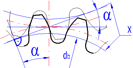
The letter "X" marks the basic circles.
Increasing the pressure angle leads to:
Selection of the values:
In case of no requirements for the designed gearing, it is recommended to use 20°.
Toothing with base helix angle = 0 (straight toothing) is used rarely, only for less loaded gearing up to a circumference speed of approx. 5 m/s (10 ft/s). Wheels with oblique or curved teeth are used for higher speeds. Values between 20° and 40° (usually per 5°) are chosen for straight oblique teeth.
According to the direction of the teeth pitch, right and left wheels are distinguished. The teeth of wheels in the mesh must have opposite directions of curving. The gearing as a unit is characterised by the direction of curving of the pinion teeth.
In case of gearing with oblique and curved teeth, a rotary movement mostly in one direction is desired. The direction of teeth curving is then chosen to push the wheels out of the mesh by axial forces (the teeth enter the mesh by their thicker ends on the outer surface of the wheels).
The illustration shows the direction of the pinion teeth pitch:
A - Left
B - Right
Using the slider adjust the value of the dimensionless coefficient that shows the ratio between the toothing width and surface straight line of the cone [4.7].
This parameter can be used to design the module size and thus the basic geometric parameters of the wheel.
Low to medium loaded gearings: 0.2 - 0.3
Highly loaded gearings: 0.3 - 0.35
Adjusting this parameter can be performed using the slider that is located on row [4.6]. After adjusting this parameter press the button "Design gearing". This procedure executes a design of toothing that meets the requirements of the desired safety [2.9] and other input parameters.
In case you tick the button on row [4.9], the maximum possible value of the toothing width to the surface straight line Re and to the tangential module on the outer perimeter met is chosen automatically.
After "Design gearing" is executed, check the dimensions (widths and diameters of the wheels and their weights). In case the result is not satisfactory, modify the input parameters of the gearing and repeat the "Design gearing".
This is the most important parameter that determines the teeth site and thus the size of the gearing. In general it is applicable that a smaller module can be used for a higher number of teeth (higher value P with inch-version of the calculation) and vice versa. In the right pop-up list you can find standardised values of the module / (Diametral Pitch with inch-version of the calculation) and the value selected from this list is automatically entered into the field on the left.
The module can be entered using an option between the normal module "mmn" (toothing with curved teeth) and tangential module "met" (straight and oblique toothing) by the respective setting in the selection list.
After clearing the button the value of the face width can be entered. Ticking the button automatically selects the maximum value.
It is calculated as the weight of solid wheels (without lightening or holes, see the illustration). It can be used for fast orientation during the design procedure.
This row always gives the lower of the coefficients for the pinion and wheel. The first column shows the safety coefficient for fatigue in the contact, the other column shows the safety coefficient for bending fatigue.
Radial (height) and tangential (perimetral) displacement of the cutters in
the course of the production process can change the geometric, kinematic and
strength characteristics of the toothing. The radial (height) displacement is
determined by the coefficient x, the tangential (perimetral) displacement is
determined by the coefficient
Both values can be adjusted in this paragraph.
Correction of toothing can lead to:
Select one of the recommended types of correction in the selection list. The recommended values x1 and xt are in row [5.2].
The practice permits slight undercutting of teeth. The given value is the minimum (limit) which leads to permissible undercutting of teeth. The correction value should not be lower except in some special cases.
It is the minimum correction value that can be used to avoid undercutting of teeth.
This slider is designed for fast changes in the correction. In case the field to the right of the slider is ticked, movements of the slider control the amount of correction x. This function can be used at the moment when you wish to optimise some of the qualitative or strength parameters of toothing; the most important of them are given in rows [5.8-5.11].
Here you can find the value of pinion displacement x1 and wheel displacement x2. In case you wish to enter a unit displacement of the pinion using the keyboard, clear the box in row [5.5].
Gear ratio |
x1 |
| 1 | 0 |
| 1.12 | 0.10 |
| 1.25 | 0.19 |
| 1.6 | 0.27 |
| 2 | 0.33 |
| 2.5 | 0.38 |
| 3 | 0.40 |
| 4 | 0.43 |
| 5 | 0.44 |
| 6 | 0.45 |
Adjust the value of the unit change of the tooth thickness here.
Gear ratio |
xt |
| 1 | 0 |
| 1.12 | 0.010 |
| 1.25 | 0.018 |
| 1.6 | 0.024 |
| 2 | 0.030 |
| 2.5 | 0.039 |
| 3 | 0.048 |
| 4 | 0.065 |
| 5 | 0.082 |
| 6 | 0.100 |
It is advisable to monitor the behaviour of these indexes when changing the corrections. Exceeding critical values is indicated by a change in the digit colour.
For a detailed explanation, see [8.1] and [8.2]
It is a dimensionless parameter (ratio of the tooth thickness and module) and depends, above all, on the tooth shape. It is influenced by the following parameters:
Usually it is 0.25 - 0.4. It is higher for low values of unit displacement and hardened wheels. A lower value than the recommended one is indicated by a red text, exceeding the limit of the tooth sharpness is indicated by a red field.
For detailed information, see [10].
This paragraph gives a well arranged listing of all basic dimensional parameters of toothing. For clarity you can find here an illustration of the most important dimensional parameters. It is recommended to use specialized literature for more a detailed explanation of individual parameters.
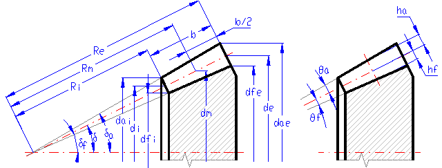
Marking of dimensions according to ISO (DIN)
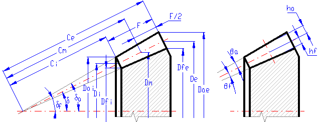
Marking of dimensions according to ANSI (AGMA)
Each conical wheel (straight, oblique) can be assigned to a virtual cylindrical wheel with straight teeth, whose profile is in practice the same as the normal profile of a conical wheel in its mean central section. Parameters of this comparative wheel can be found in this paragraph.
This includes the parameters which inform us of the quality of the designed toothing. It is advisable to compare them with the recommended values.
For smooth meshing of gears, it is necessary that the other pair of teeth enters in meshing before the first pair is released. The contact ratio in the face plane says how many teeth are in meshing simultaneously. With the value ea=1 this corresponds to a limit case when only one pair of teeth is in meshing at the given moment. With the value
According to the complexity of the gearing, this parameter should not be lower than 1.1 to 1.2.
This is the sum of transverse contact and overlap ratios.
This is specified using the same recommendations as
This is the speed at which the angle speed is the same as the proper angle vibration frequency of the gearing.
This is the ratio of pinion speed and "Critical speed".
In case the designed gearing works in the range of critical speed (N ~ 1), the resonance ratio N is indicated by a red number. In such cases, modifications of the designed gearing (changes of numbers of teeth) or consultations with a specialist are recommended.
It is roughly calculated as the weight of the solid wheel (without holes for shafts or lightening holes) according to the illustration with the real dimensions of the toothing in par. [4.0]. It can be used for fast orientation in the design.
Exact determination of the coefficient is difficult. Therefore, an approximate calculation based on the number of teeth, mesh coefficient, angle beta and friction coefficient is used. The choice of friction coefficient is based on the chosen level of toothing accuracy [2.6] within the range 0.04-0.08
The standard DIN 3991 defines 4 levels (A, B, C, D) of complexity of the determination of the coefficient used for calculating safety coefficients. The coefficients are mostly determined in this calculation using the methodology B or C (exceptionally D). Detailed information and formulas for determination of the respective coefficients can be found in the appropriate standard.
The life coefficient [9.18, 9.29] – According to DIN 3991 the value of the contact and bending fatigue for the given number of cycles is used directly. This calculation uses the basic value of the fatigue limit multiplied by the respective life coefficient calculated from the basic number of loading cycles, exponent of the Wohler’s curve and the actual number of cycles.
According to DIN 3991 the coefficient of alternate loading [9.27] and coefficient of production technology [9.28] are not considered here. Therefore, the values of these coefficients are set to 1.0.
The methodology according to standards
Two basic strength calculations are usually carried out, namely for bend and for contact. The following safety coefficients are calculated in this calculation:
As initial values of the safety coefficient you can use:
Safety coefficients can then be modified according to general recommendations for options of safety coefficients and according to your own experience.
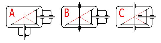
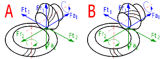
In loaded gearing there appear some forces that are transferred to the machine structure. Knowledge of these forces is fundamental for correct dimensioning of the equipment. The orientation of the forces can be seen in the following illustration. Row [11.3, 11.4] shows the amounts of the forces if the sense of rotation of the gearing agrees with the directions in the illustration, row [11.5, 11.6] shows the amounts of forces if the directions are opposite. In case the amount of the force is negative, it acts in the opposite direction than as illustrated. Illustration A shows the left direction of the pitch, illustration B the right direction. The pitch direction can be chosen in row [4.5].
It is another important qualitative parameter that affects the desired accuracy of the gearing [2.6] and the manner of lubrication (Lubrication of wheels). The maximum recommended speed for the chosen level of accuracy is shown in the green cell on the right.
It is another qualitative index that is used for the calculation "Indexes of irregularity of loading of the tooth".
This paragraph enables an orientation calculation of the lost heat and gearbox surface necessary for dissipation of this heat.
Temperature of the oil in the gearbox should be in a range from 50 to 80 °C; a lower temperature should be found in smaller modules. More exact determination of temperature depends on the chosen construction and used materials. Higher temperatures bring a danger of lower backlash and the gearing could seize.
This depends on the construction and ambient environment of the gearbox. Initially, it is possible to choose:
for ISO/DIN:
for ANSI/AGMA:
This depends on the total transferred power and efficiency of the gearing.
This parameter gives the minimum surface of the gearbox necessary for dissipation of power losses and maintaining the desired oil temperature.
Diameters of shafts (steel) that correspond to the desired load (transferred power, speed) are designed in this paragraph. These values are for orientation only; the final design should be made using a more exact calculation.
Auxiliary calculations are available in this paragraph. When entering values, use the same units as in the main calculation. To transfer the entered and calculated values to the main calculation, press the button "OK".
Use the following table for your decision on the manner of lubrication of the gearing.
| Type of lubrication | Peripheral speed in | |
| [m/s] | [ft/min] | |
| Oil-bath lubrication | < 12 | < 2400 |
| Pressure spray lubrication | > 12 | > 2400 |
| Oil-mist lubrication | > 60 | > 12000 |
Information on options of 2D and 3D graphic outputs and information on cooperation with 2D and 3D CAD systems can be found in the document "Graphic output, CAD systems".
This parameter determined the radius of the cutting tool in the production of circular teeth. It must be used only as a model in the 3D CAD system (if the respective model supports detailed toothing).
These parameters set the offset amount with the toothed wheel, see the illustration.
Information on setting of calculation parameters and setting of the language can be found in the document "Setting calculations, change the language".
General information on how to modify and extend calculation workbooks is mentioned in the document "Workbook (calculation) modifications".
Material list - Method of heat treatment
1...Non-treated thermally, annealed normalizationally
2...Upgraded
3...Cemented, hardened, surface hardened
4...Nitrided
^