Dans cette partie, vous trouvez certaines informations théoriques et formules relatives à la conception de la géométrie, au calcul des paramètres de la résistance et de la puissance et au contrôle de la résistance de la denture en développante.
Certaines des formules les plus importantes pour le calcul de la géométrie de
la denture sont indiquées ci-après. Les indices 1 et 2 sont utilisés dans les
formules pour le pignon et le planétaire (ce qui correspond à la paire :
planétaire intérieur et satellite, ou encore satellite et planétaire extérieur).
Dans le cas d’une denture intérieure (planétaire extérieur), la valeur négative
du nombre de dents de la roue intérieure et la valeur négative de la distance à
l’axe et des diamètres sont utilisées.
Dans le cas d’un train épicycloïdal, toutes les roues sont mutuellement
dépendantes et il est nécessaire de concevoir la transmission comme un ensemble,
c'est-à-dire de prendre également en compte les conditions limitantes
correspondantes (voir ci suit).
Paramètres du profilé élémentaire: mn (module, DP pour calcul en
pouces),
a (angle d’engrenage), ha*, c*, rf*
(paramètres de la machine outil)
Paramètres du pignon et du planétaire: z1, z2 (nombre de dents du pignon
et du planétaire), x1, x2 (modification supplémentaire), b
(angle d’inclinaison des dents), b (largeur de la denture)
L'approche ou l'éloignement de l'outil de production du centre de la roue change la forme et donc les propriétés de la denture spirale. Ce qui crée une denture corrigée. Dans l'image il y a:

La correction de la denture permet de:

Exemple d'un profil de dent (z=10,
En déterminant les valeurs de correction, il est nécessaire de remplir d'abord les conditions de fonctionnement de la denture, où les articles les plus importants comprennent:
Pendant la détermination des conditions de fonctionnement, il est encore possible d'optimiser les corrections pour améliorer un ou plusieurs paramètres importants de l'engrenage. A partir des méthodes d'optimisation souvent utilisées, il est possible d'optimiser la denture pour le calibrage des glissades spécifiques [5.10, 5.11] et la minimalisation des glissades spécifiques [5.12]. La littérature spécialisée offre toute une série de recommandations sur les autres procédures d'optimisation et surtout les diagrammes (tableaux) des corrections de limite qui donnent des vues d'ensemble sur les possibilités et le choix des corrections.
Moment de torsion
Mk [Nm] = Pw * 9550 / n .............. (SI units)
T [lb.in] =
Pw, PP ...
n ...........
Puissance denture droite - la
Crémaillère
Pw = Ft * v / 1000
Ft ... Force
tangentielle
v .... crémaillère de vitesse
Ft = Mk * 2000 / dw
dw ... Diamètre opérationel du pas
MK ...
Force axiale
Fa = Ft * tan(b) / cos(awt)
Force radiale
Fr = Ft *
Force normale
Fn = (Ft2 + Fa2 + Fr2)0.5
Moment de flexion
Mo = Fa * (dw / 2000)
Les pertes dans le train épicycloïdal peuvent être divisées en perte par ralenti ou par charge. Les pertes par ralenti (graissage, engrenage non sollicité, roulement) sont difficiles à déterminer analytiquement et sont habituellement nettement inférieures aux pertes par charge. Les pertes par charge apparaissent lors du transfert de puissance, ce sont :
Le coefficient de perte peut approximativement être exprimé selon la formule :
denture droite : zz = 0.5 • f •
p
• e • (1/z1 +- 1/z2)
denture oblique : zz
= 0.25 / cos(b) • f •
p • e •
(1/z1 +- 1/z2)
où :
z1, z2 – nombre de dents
f – coefficient de friction (0.04 - 0.08)
e –
coefficient de contact
b –
angle d’inclinaison des dents
Signe (+) pour une denture extérieure, (-) pour une denture intérieure.
La perte de puissance peut être
exprimée avec la relation :
PVL = w • F • f • r
où :
w – vitesse angulaire
F – charge totale du roulement (porte satellite, force centrifuge)
f – coefficient de friction (0.001 - 0.005)
r – rayon moyen du roulement
Pour le calcul des pertes (rendement) de l’engrenage planétaire, nous utilisons les mêmes pertes que dans un engrenage classique (porte satellite en arrêt) où :
où :
zz0/z1 – coefficient de
perte : planétaire intérieur - satellite
zz1/z2 – coefficient de
perte : satellite – planétaire extérieur
z0,z2 – nombre de dents des
planétaires extérieur et intérieur
Pour les cas individuels de flux de puissance, le calcul de perte suivant est
valide :
| z = ir • zr / (ir - 1) | Planétaire intérieur => Satellite (porte satellite) |
| z = zr | Planétaire intérieur => Planétaire extérieur |
| z = ir • zr / (ir - 1 + zr ) | Satellite (porte satellite) => Planétaire intérieur |
| z = - zr / (ir - 1) | Satellite (porte satellite) => Planétaire extérieur |
| z = - zr / (ir - 1 - ir • zr) | Planétaire extérieur => Satellite (porte satellite) |
| z = zr | Planétaire extérieur => Planétaire intérieur |
Les trains épicycloïdaux sont formés d’un système de roues dentées et de porte satellites. Les roues dentées centrales sont coaxiales avec le porte satellites et l’axe central du mécanisme de transmission. Les satellites sont des roues dentées qui tournent sur le porte satellites et qui sont engrenés avec le planétaire intérieur ou entre eux. Les satellites peuvent avoir une, deux ou plusieurs dentures. Les satellites à deux ou plusieurs degrés présentent plusieurs variantes de constructions avec de plus grandes possibilités, ils sont cependant plus compliqués et donc plus chers de fabrication.
Un exemple de train épicycloïdal simple avec un satellite denté à une vitesse est donné ci-dessous. Ce type élémentaire de train épicycloïdal est ensuite totalement étudié dans ce logiciel.
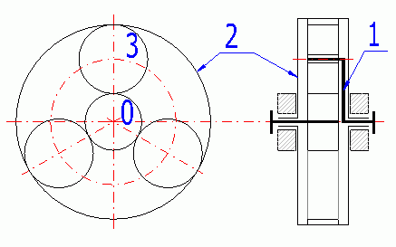
0 – Planétaire intérieur ; 1- Porte satellite ; 2 – Planétaire extérieur ; 3 - Satellite
Si pour un train épicycloïdal simple, les trois éléments (0, 1, 2) sont libres,
il s’agit d’un différentiel (2 degrés de mobilité) qui permet d’associer / de
dissocier deux mouvements en un. Cela est par exemple utilisé pour les
machines-outils (association) ou pour les différentiels automobiles
(dissociation du mouvement).
Si l’un des éléments élémentaires (0 ou 2) est fixé au bâti, il s’agit d’un train épicycloïdal (1 degré de mobilité) : dans le cas d’une transmission depuis le planétaire intérieur, il s’agit d’un réducteur et dans le cas d’une transmission depuis le porte satellite, il s’agit d’un multiplicateur. Si le porte satellite est fixé au bâti, il s’agit d’une transmission habituelle, c'est-à-dire d’un engrenage classique.
Les trains épicycloïdaux peuvent être configurés de différentes façons. La configuration la plus fréquente est de les mettre les uns derrière les autres, cas où le rapport de transmission total (efficacité) est donné par le produit des rapports de transmissions partielles (efficacités). La possibilité de freiner les différents éléments, c’est-à-dire de changer de vitesses, est souvent utilisée pour les trains épicycloïdaux assemblés.
• Gain de place grâce à une disposition coaxiale de l’arbre moteur et de
l’arbre récepteur
• Poids plus faible par rapport à une transmission habituelle
• Grande efficacité même pour de grandes puissances transmises
• Charge radiale faible des roulements des éléments centraux
• Construction compacte
• Construction plus complexe, exigences plus importantes de précision de
fabrication et de montage
• Coûts de fabrication élevés
• Certaines conditions limitantes (« montabilité »)
Étant donnée la liste des avantages indiqués, l’utilisation des trains épicycloïdaux est de plus en plus fréquente dans un grand nombre de domaines (par exemple les boites de vitesse des véhicules à moteur, les machines de construction, les dispositifs de levage, les boites de vitesse de bateaux, les réducteurs de turbine etc.). Le train épicycloïdal est souvent relié à une transmission hydraulique ou à friction.
Les indices suivants sont utilisés dans les formules mentionnées.
Pour :
- planétaire intérieur – 0
- satellite – 1
- planétaire extérieur - 2
Pour permettre le montage et le fonctionnement de l’engrenage de transmission, il n’est pas possible de choisir la géométrie des roues dentées arbitrairement. Pour un bon fonctionnement, il est nécessaire d’observer et de respecter les quelques conditions suivantes :
Les satellites des engrenages de transmission engrènent avec les planétaires intérieurs et éventuellement avec d’autres satellites. Dans le cas de ce calcul, il y a engrenage commun du satellite et du planétaire intérieur (arbre planétaire, planétaire extérieur). Le planétaire intérieur ayant un axe commun avec le planétaire extérieur, la distance axiale entre le satellite et les deux planétaires doit être identique.
Pour des roues généralement corrigées, il est donc vrai que :
aw (0,1) = aw (1,2)
où aw (0,1)=mt • (z0+z1)/2 • COS(alfat)/COS(alfawt(0,1))
où aw (1,2)=mt • (z1+z2)/2 • COS(alfat)/COS(alfawt(1,2))
Pour des satellites simples et pour des satellites uniformément répartis, il
est indispensable de remplir la condition suivante :
g = (abs (z0) + abs (z2))/P
où :
g – nombre arbitraire entier
P – nombre de satellites
z – nombre de dents
Cette condition assure un jeu minimum entre les satellites vmin (1 à 2 mm,
0,05 in).
Nombre total de satellites P = int(asin((da1+vmin)/(aw • 2)))
Il s´agit d´un calcul standard de la denture où le pignon et la crémaillère s´engrènent l´un dans l´autre. Pour le pignon aussi bien que pour la crémaillère, il est possible de définir le profil de l´outil de production.
Dans le calcul, il est possible de sélectionner le nombre de dents du pignon, l´angle d´engrenage et l'angle d'inclinaison de la denture. Dans ce cas, la correction de la crémaillère n´a pas de sens. Il est possible de corriger seulement le pignon (distance axiale, amélioration des conditions d´engrènement, amélioration des paramètres de la résistance).
Dans le calcul, il est possible d´entrer la force tangentielle, ce qui est en fait la force exercée par la crémaillère sur le pignon, et la vitesse de la crémaillère (vitesse périphérique du pignon). A partir de ces deux valeurs, on calcule la puissance transférée et le moment de torsion du pignon. En vue du fait que la crémaillère peut être utilisées dans toute la série de solutions, il est nécessaire de transformer (calculer) les exigences concernant la transmission dans ces deux valeurs.
Comme il n'existe aucune norme relative au calcul de la résistance du système pignon/crémaillère, notre calcul de la résistance repose sur la norme ISO6336(ANSI/AGMA2001-D04). Ici, la crémaillère est remplacée par une roue dentée ayant un grand nombre de dents (1000 dents).
Il n´existe aucune méthode exacte pour déterminer la vitesse critique de rotation de la crémaillère. Pour effectuer une estimation brute, vous pouvez utiliser le calcul de deux roues couronnées (une roue dentée en remplacement de la crémaillère).
Pour une crémaillère légère qui n´est pas liée à la structure, utilisez le coefficient sR/h=1, pour une crémaillère liée à la structure, utilisez sR/h=20.
Pour déterminer le facteur de la durée de vie (YNT, ZNT), il est nécessaire de connaître le nombre de cycles. Saisissez le nombre de cycles pour le pignon et la crémaillère.
Dans les paragraphes suivants, on décrit la méthode de calcul de la capacité de charge. Dans le calcul, la norme ISO6336:2006 est utilisée. La description contient les formules clés conjointement avec les notes pertinentes pour comprendre le calcul et la commande de ce programme. Ce texte ne remplace en aucun cas le texte complet des normes utilisées.
This part of ISO 6336 presents the basic principles of, an introduction to, and the general influence factors for, the calculation of the load capacity of spur and helical gears.
Ft = 2000 * T1,2 / d1,2 = 19098 * 1000 * P / (d1,2
* n1,2) = 1000 * P / v
w1,2 = 2000 * v / d1,2
= n1,2 / 9549
Ft ... (nominal) transverse tangential load at reference cylinder per mesh
T1,2 ... nominal torque at the pinion (wheel)
d1,2 ... reference diameter of pinion (wheel)
P ... transmitted power
n1,2 ... rotation speed of pinion (wheel)
v ... tangential velocity (without subscript, at the reference circle
=tangential velocity at pitch circle)
w1,2 ... angular velocity of
pinion (wheel)
The application factor, KA, is used to modify the value of Ft to take into account loads additional to nominal loads, which are imposed, on the gears from external sources. The empirical guidance values in table B.1 ISO 6336-6 can be used (for industry gears and high speed gears).
(The internal dynamic factor KV makes allowance for the effects of gear tooth accuracy grade as related to speed and load.
There are three calculation methods (B2006), (C2006) a (C1996).)
La méthode B va bien avec tous les types de roues dentées cylindriques. Elle est relativement compliquée et si vous ne choisissez pas bien le matériau et le degré de précision par rapport à la charge, les valeurs KV peuvent être hors de la réalité. La méthode C peut être utilisée lors du respect de certaines limitations. C´est pourquoi il est possible d´ajuster le plafond KV (préajusté à 5.0). En cas de dépassement, il convient de contrôler le matériau sélectionné par rapport à la charge de la denture.
Internal dynamic factor KV(B)
N = n1 / nE1
For N < NS (Subcritical range)
NS = 0.5 + 0.35 * ( Ft * KA / b )0.5
...... [ Ft * KA / b < 100 ]
NS = 0.85 ...... [ Ft * KA / b >= 100 ]
KV(B) = ( N * K ) + 1
K = ( CV1 * BP ) + ( CV2 * Bf ) + (
CV3 * BK )
BP = c' * fpb eff / ( Ft
* KA / b )
Bf = c' * fta
eff / ( Ft * KA / b )
BK = abs (1 + c' * Ca / ( Ft
* KA / b ))
For Ns < N < 1.15 (Main
resonance range)
KV(B) = ( CV1 * BP ) + ( CV2
* Bf ) + ( CV4 * BK )
+ 1
For N >= 1.5 (Supercritical range)
KV(B) = ( CV5 * BP ) + ( CV6
* Bf ) + CV7
For 1.15 < N < 1.5 (Intermediate range)
KV(B) = KV(N=1.5) + (
KV(N=1.15) - KV(N=1.5)) / 0.35 * (1.5 - N)
Coeficients
|
1.0 < eg <=2.0 | eg > 2.0 |
| CV1 | 0.32 | 0.32 |
| CV2 | 0.34 | 0.57 / (eg - 0.3) |
| CV3 | 0.23 | 0.096 / (eg - 1.56) |
| CV4 | 0.90 | (0.57 - 0.05 * eg ) / (eg - 1.44) |
| CV5 | 0.47 | 0.47 |
| CV6 | 0.47 | 0.12 / (eg - 1.74) |
| CV7 | 1.0 < eg <=1.5 | 0.75 |
| CV7 | 1.5 < eg <=2.5 | 0.125 * sin(p * (eg - 1.74)) + 0.875 |
| CV7 | eg > 2.5 | 1.0 |
| Cay1,2 | 1 / 18 * (sHlim1,2 / 97 - 18.45)2 + 1.5 | |
| Cay | 0.5 * (Cay1 + Cay2) | |
| Ca | Ca = Cay | |
Internal dynamic factor KV(C)
Method C supplies average values which can be used for industrial transmissions and gear systems with similar requirements in the following fields of application:
Method C can also generally be used, with restrictions for the following fields of application:
Method (C2006) is different from (C1996) by adding the
coefficient K3.
Example for input values KA * Ft / b = 100; v = 3 m / s; Q = 7 and straight
teeth.
1996.gif)
2006.gif)
KV(C..1996)
KVa,b = 1 + (K1 / ( Ft * KA
/ b ) + K2) * v * z1 / 100 * (u2 / (1 + u2))0.5
... [ eb
= 0; eb
>= 1.0]
KV(C..2006)
KVa,b = 1 + (K1 / ( Ft * KA
/ b ) + K2) * v * z1 / 100 * K3 * (u2 / (1 + u2))0.5
... [ eb
= 0; eb
>= 1.0]
KV = KVa - ea* ( KVa - KVb ) ... [0 < eb < 1.0]
Coeficients
| K1 (Accuracy grades as speclfled in ISO1328-1) | K2 | ||||||||||
| 3 | 4 | 5 | 6 | 7 | 8 | 9 | 10 | 11 | 12 | All | |
| Spur gears eb = 0 | 2.1 | 3.9 | 7.5 | 14.9 | 26.8 | 39.1 | 52.8 | 76.6 | 102.6 | 146.3 | 0.0193 |
| Helical gears eb >=1.0 | 1.9 | 3.5 | 6.7 | 13.3 | 23.9 | 34.8 | 47.0 | 68.2 | 91.4 | 130.3 | 0.0087 |
| SRC = v * z1 / 100 * (u2 / (1 + u2))0.5 | |||||||||||
| K3 = 2.0 ...... [SRC <= 0.2] | |||||||||||
| K3 = -0.357 * SRC + 2.071 ...... [SRC > 0.2] | |||||||||||
nE1 = 30000 / ( p * z1 ) * ( cga / mred )0.5
mred = m*1 * m*2 / ( m*1
+ m*2 )
m*1,2 = J*1,2 / (rb 1,2)2
[kg/mm]
J*1,2 = J1,2 / b1,2
cga = c'
* (0.75 * ea
+ 0.25)
c' = c'th * CM * CR * CB * CE
* CFK * cos(b)
c'th = 1 / (0.04723 + 0.15551/zn1 + 0.25791/zn2
- 0.00635*x1 - 0.11654*x1/zn1 - 0.00193*x2
- 0.24188*x2/zn2 + 0.00529*x12 +
0.00182*x22)
c'th = 1 / (0.04723 + 0.15551/zn1 - 0.00635*x1 - 0.11654*x1/zn1 - 0.00193*x2 + 0.00529*x12 +
0.00182*x22) ... for internal gearing
CM = 0.8
CR = 1 + ln(bs / b) / (5 * e(sR/(5 * mn)))
...... [0.2 < bs < 1.2 ]
CB = 0.5 * (CB1 + CB2); CB1,2 = (1 +
0.5 * (1.2 - hf1,2 / mn)) * (1 - 0.02*(20 -
aPn))
CE = (( 2 * E1 * E2 ) / ( E1 + E2
)) / 206
CFK = (( Ft * KA / b ) / 100 )0.25......
[ CFK<= 1.0 ]
zn1,2 = z1,2 / cos(b)3
Main resonance of gear with idler gears, inner gears and planet gears are calculated by different process. Details in ISO6336-1.
This coefficient takes into account the effect of the non-uniform distribution of load over the gear face. Uneven load distribution is caused by an elastic deformation of gears and housing, manufacturing deviations and thermal distortion. Methods, principles and assumptions are given in standard ISO6336-1. Because the determination of the coefficient is dependent on a number of factors and primarily on the specific dimensions and design of the gearbox, is for the design purposes selected the coeficient KHb from graphs based on practical experiences. The calculation is in paragraph [18].
Detail description is in ISO6336-1. Here is just a selection of formulas, information and comments that are related to the calculation KHb.
a) KHb = (2 * Fby * cgb
/ (Fm / b))0.5 ...... [ Fby
* cgb / (2 * Fm / b) >= 1.0;
KHb >= 2.0 ]
b) KHb = 1 + Fby * cgb
/ (2 * Fm / b) ...... [ Fby
* cgb / (2 * Fm / b) < 1.0;
KHb > 1.0 ]
Fm = Ft * KA * KV
Fby = Fbx * yb
cgb = 0.85 * cga
b ...... gear width
yb ... Running-in allowance from graph
1) Fbx = Choosing your own values
2) Fbx = 1.33 * B1 * fsh
+ B2 * fma ....... [ Fbx >= Fbxmin
]
3) Fbx = abs( 1.33 * B1 * fsh - fHb6)
...... [ Fbx >= Fbxmin
]
4) Fbx = 1.33 * B1 * fsh +
fsh2 + fma + fca +fbe
B1, B2 coeficients, table 8, ISO6336-1
fHb6 ... Helix slope deviation for Q=6,
ISO1328-1
fsh ... Component of equivalent misatignment. It is possible to use several
methods (calculation, measurement, estimation). Used formula:
fsh = Fm / b * 0.023 * (abs(B' + K'
* l * s / d12 * (d1 / dsh)4 - 0.3) + 0.3) * (b / d1)2
... [s / l < 0.3]
fsh = Fm / b * 0.046 * (abs(B' + K'
* l * s / d12 * (d1 / dsh)4 - 0.3) + 0.3) * (bB / d1)2
... [s / l < 0.3]
fsh2, fca, fbe ... can be determined by ISO6336-1
B' = 1.0 ... for both spur and single helical gears, for the total transmitted
power
K' = arrangement coefficient, gray indicates the less deformed helix of a double
helical gear
| K' | with stiffening | without stiffening |
| A | 0.48 | 0.80 |
| B | -0.48 | -0.80 |
| C | 1.33 | 1.33 |
| D | -0.36 | -0.60 |
| E | -0.60 | -1.00 |
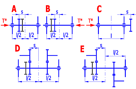
l, s .... picture
dsh ... shaft diameter
fma ... mesh misalignment. It is possible to use several
methods (calculation, measurement, estimation). Used formula:
fma = (fHb12 + fHb22)0.5
.
a) KHb = Acoef * (2 * Fby * cgb
/ (Fm / b))0.5 ...... [ Fby
* cgb / (2 * Fm / b) >= 1.0;
KHb > 1.0 ]
b) KHb = Acoef * (1 + Fby * cgb
/ (2 * Fm / b)) ...... [ Fby
* cgb / (2 * Fm / b) < 1.0;
KHb > 1.0 ]
Fm = Ft * KA * KV
Fby = Fb * 0.8
..... [Fb from ISO 1328]
cgb = 0.85 * cga
b ...... gear width
Acoef = 1.0 ..... Double-sided symmetrically supported gearing
Acoef = (0.9 + 0.15 * (b1 / d1)2 + 0.23 * (b1 / d1)3)
..... Double-sided non-symmetrically supported gearing
Acoef = (0.9 + (b1 / d1)2) ..... Overhung gearing
For the preliminary design is possible to use values from these graphs.
X Axis: Ratio gear width to gear diameter
Y Axis: Factor KHb ..... [min. value = 1.05]
Accuracy grade 7
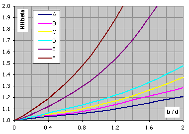
Not-hardended gears, VHV<370, design type A-F ... calculation paragraph [2.0]
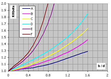
Hardended gears, VHV<=370, design type A-F ... calculation paragraph [2.0]
KFb = ( KHb )NF
NF = (b / h)2 / (1 + b / h + (b / h)2) ...... [když
b / h < 3; pak b / h = 3] ([if b / h < 3; then b / h = 3])
The smaller of the values b1/h1, b2/h2 is to be used as b/h.
KHa = KFa =
eg
/ 2 * (0.9 + 0.4 * (cga
* (fpb - ya)) / (FtH
/ b)) ...... [eg
<= 2.0]
KHa = KFa =
0.9 + 0.4 * (2.0 * (eg
- 1.0) / eg)0.5
* cga * (fpb
- ya) / (FtH /
b) ...... [eg
> 2.0]
Pro: (For:)
KHa >
eg
/ (
ea
* Ze2)
...... KHa =
eg
/ (
ea
* Ze2)
KHa <
1.0 ...... KHa
= 1.0
Pro: (For:)
KFa >
eg
/ (0.25 *
ea
+ 0.75) ...... KFa =
eg
/ (0.25 *
ea
+ 0.75)
KFa <
1.0 ...... KFa
= 1.0
fpb = fpt (ISO1328-1)
ya ... Material: St, St(cast),
V, V(cast), GGG(perl.), GGG(bai.), GTS(perl.)
ya = fpb * 160 /
σHlim [ v < 5m/s ]
ya
<= 12800 / σHlim [ 5m/s < v <= 10m/s ]
ya
<= 6400 / σHlim [ v > 10m/s ]
ya ... Material: GG,
GGG(ferr.)
ya = fpb 0.275
[ v < 5m/s ]
ya
<= 22 [ 5m/s < v <= 10m/s ]
ya
<= 11 [ v > 10m/s ]
ya ... Material:
Eh, IF, NT(nitr.), NV(nitr.), NV(nitrocar.)
ya = fpb 0.075
[ ya
<= 3 ]
This part of ISO 6336 specifies the fundamental formulae for use in the determination of the surface load capacity of cylindrical gears with involute external or internal teeth. It includes formulae for all influences on surface durability for which quantitative assessments can be made. lt applies primarily to oil-lubricated transmission, but can also be used to obtain approximate values for (slow-running) grease-lubricated transmissions, as long as sufficient lubricant is present in the mesh at all times.
Safety factor for surface durability (against pitting), SH
Calculate SH separately for pinion and wheel:
SH1,2 = σHG1,2 / σH1,2 > SHmin
σH1 = ZB * σH0 * (KA * KV * KHb
* KHa)0.5
σH2 = ZD * σH0 * (KA * KV * KHb
* KHa)0.5
The
nominal contact stress at the pitch point σH0
σH0 = ZH * ZE * Ze
* Zb * (Ft / (b * d1)
* (u + 1) / u)0.5
σHP = ZL * ZV * ZR * ZW * ZX * ZNT * σHlim / SHmin = σHG / SHmin
The pitting stress limit σHG
σHG = σHP * SHmin
ZH = (2 * cos(bb) * cos(awt) / (cos(at)2 * sin(awt)))0.5
M1 = tan(awt) /
((((da1 / db1)2 - 1.0)0.5 - 2 *
p / z1) * (((da2 / db2)2
- 1.0)0.5 - (ea
- 1.0) * 2 * p / z2))0.5
M2 = tan(awt) /
((((da2 / db2)2 - 1.0)0.5 - 2 *
p / z2) * (((da1 / db1)2
- 1.0)0.5 - (ea
- 1.0) * 2 * p / z1))0.5
Spur gears with, ea
> 1.0
ZB = 1.0 ... [ M1<= 1.0 ]
ZB = M1 .... [ M1 > 1.0 ]
ZD = 1.0 ... [ M2<= 1.0 ]
ZD = M2 .... [ M2 > 1.0 ]
Helical gears with, eb
>= 1.0
ZB = ZD = 1.0
Helical gears with, eb
< 1.0
ZB = M1 - eb
* (M1 - 1.0) ... [ ZB >= 0 ]
ZD = M2 - eb
* (M2 - 1.0) ... [ ZD >= 0 ]
(For internal gears, ZD shall be taken as equal to 1.0)
ZE = (p * ((1.0 - n12) / E1 + (1 - n22) / E2))-0.5
n1,2 ... Poisson's ratio
E1,2 ... modulus of elasticity
Ze = ((4.0 -
ea)
/ 3 * (1.0 - eb)
+ eb
/ ea)0.5
... [ 0 <= eb
< 1.0 ]
Ze = (1.0 /
ea)0.5
... [ eb
>= 1.0 ]
Zb = 1 / (cos(b))0.5
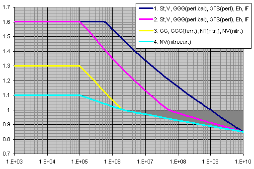
X axis ... number of cycles
Y axis ... ZNT
ZL = CZL + 4 * (1.0 - CZL) / (1.2 + 80 /
n50)2 = CZL
+ 4 * (1.0 - CZL) / (1.2 + 134 / n40)2
CZL = 0.83 ... [ σHlim < 850 ]
CZL = σHlim / 4375 + 0.6357 ... [
850 <= σHlim <= 1200 ]
CZL = 0.91 ... [ 1200 < σHlim ]
n50 (
n40) ... Nominal viscosity in 50°C (40°C) [mm2/s]
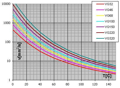
Diagram viscosity / temperature for viscosity index VI = 50
ZV = CZV + 2 * (1.0 - CZV) / (0.8 + 32 / v)0.5
CZV = CZL + 0.02
ZR = (3 / Rz10)CZR
CZR = 0.15 ... [ σHlim < 850 ]
CZR = 0.32 - 0.0002 * σHlim ... [
850 <= σHlim <= 1200 ]
CZR = 0.08 ... [ 1200 < σHlim ]
Rz10 = Rz * (10 / rred)(1/3)
rred = (r1
* r2) / (r1
+ r2)
r1,2 = 0.5 * db1,2 *
tan(awt)
The work hardening factor, ZW takes account of the increase in the surface durability due to meshing a steel wheel (structural steel, through-hardened steel) with a hardened or substantially harder pinion with smooth tooth flanks.
Pinion Surface-hardened, Gear through-hardened
ZW = 1.2 * (3 / RzH)0.15 ... [ HB < 130 ]
ZW = (1.2 - (HB - 130) / 1700) * (3 / RzH)0.15
... [ 130 <= HB <= 470 ]
ZW = (3 / RzH)0.15 ... [ HB > 470 ]
ZW for static stress
ZW = 1.05 ... [ HB < 130 ]
ZW = 1.05 - (HB - 130) / 680 ... [ 130 <= HB <= 470 ]
ZW = 1.0 ... [ HB > 470 ]
RzH = Rz1 * (10 / rred)0.33
* (Rz1 / Rz2)0.66) / (
n40 * v / 1500)0.33)
... [ 3 <= RzH <=16 ]
Through-hardened pinion and gear
ZW = 1.0 ... [ HB1/HB2 < 1.2 ]
ZW = 1.0 + A * (u - 1.0) ... [ 1.2 <= HB1/HB2
<= 1.7 ]
ZW = 1.0 + 0.00698 * (u - 1.0) ... [ 1.7 < HB1/HB2
]
A = 0.00898 * HB1/HB2 - 0.00829
ZW for static stress
ZW = 1.0
This part of ISO 6336 specifies the fundamental formulae for use in tooth bending stress calculations for involute external or internal spur and helical gears with a rim thickness sR > 0.5 * ht for external gears and sR >1.75 * mn for internal gears.
Safety factor for bending strength (safety against tooth breakage), SF
Calculate SF separately for pinion and wheel:
SF1,2 = σFG1,2 / σF1,2 >= SFmin
σF = σF0 * KA * KV * KFb * KFa
The nominal tooth root
stress σF0
σF0 = Ft / (b * mn) * YF * YS
* Yb * YB * YDT
σFP = σFlim * YST * YNT * YdrelT * YRrelT * YX / SFmin = σFG / SFmin
Tooth root stress limit σFG
σFG = σFP * SFmin
YF = (6 * hFe / mn * cos(aFen)) / ((sFn / mn)2 * cos(an))
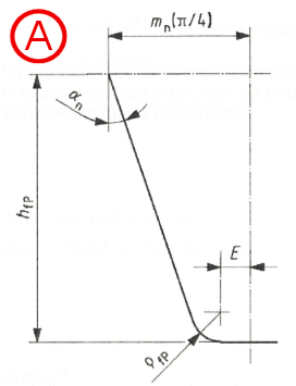
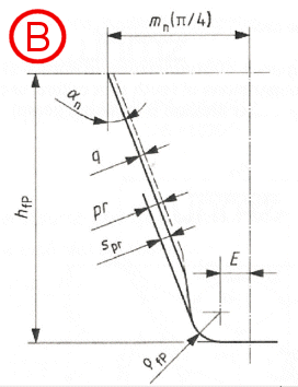
Dimensions and basic rack profile of the teeth (finished profile)
A...without undercut
B...with undercut
auxiliary values
E = p / 4 * mn - hfP
* tan(an) + spr / cos(an)
- (1 - sin(an) * rfP
/ cos(an)
spr = pr - q
spr = 0 when gears are not undercut
rfPv = rfP
... external gears
rfPv = rfP
+ mn * (x0 + hfp/mn - rfP/mn)1.95
/ (3.156 * 1.036z0) ... internal gears
x0 ... the pinion-cutter shift coefficient
z0 ... the number of teeth of the pinion cutter
G = rfPv / mn - hfP
/ mn + x
H = 2 / zn * (p / 2 - E / mn)
- T
T = p / 3 ... external gears
T = p / 6 ... internal gears
q = 2 * G / zn * tan(q)
- H
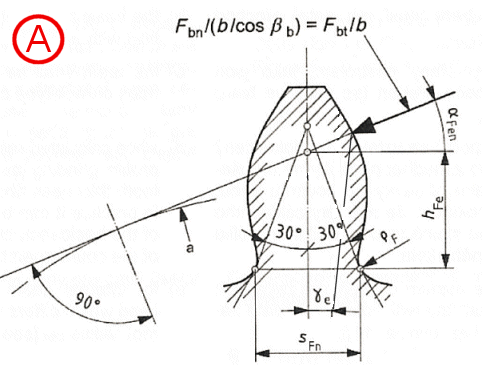
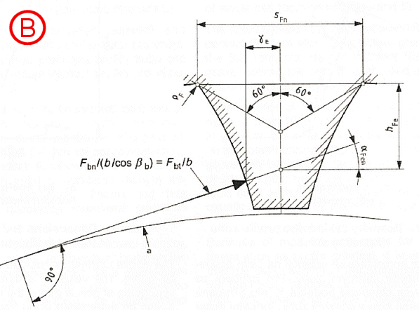
Determination of normal chordal dimensions of tooth root critical section for
Method B
A...external gears
B...internal gears
Tooth root normal chord sFn
sFn / mn = zn * sin(p/3 - q) + (3)0.5 * (G / cos(q)
- rfPv / mn) ...
external gears
sFn / mn = zn * sin(p/6 - q)
+ (G / cos(q)
- rfPv / mn) ...
internal gears
Radius of root fillet rF
rF / mn
= rfPv / mn + 2 * G2
/ (cos(q) * (zn * cos(q)2
- 2 * G))
Bending moment arm hFe
hFe / mn = 0.5 * ((cos(ge)
- sin(ge) * tan(aFen))
* den / mn - zn * cos(p/3
- q) - G / cos(q)
+ rfPv / mn)) ...
external gears
hFe / mn = 0.5 * ((cos(ge) - sin(ge) * tan(aFen)) * den / mn - zn * cos(p/6 - q) - (3)0.5 * (G / cos(q) - rfPv / mn))) ... internal gears
Parameters of virtual gears
bb = arcsin(sin(b)
* cos(an))
zn = z / (cos(bb))3
ean=
ea / (cos(bb))2
dn = mn * zn
pbn = p * mn *
cos(an)
dbn = dn * cos(an)
dan = dn + da - d
den = 2 * z / abs(z) * ((((dan / 2)2 - (dbn
/ 2)2)0.5 - p * d *
cos(b) * cos(an)
* (ean - 1) / abs(z))2
+ (dbn / 2)2)0.5
*The number of teeth z is positive for external gears and negative for internal gears
aen = arccos(dbn /
den)
ge = (0.5 * p
+ tan(an) * x) / zn +
inv(an) - inv(aen)
aFen = aen
- ge
The stress correction factor YS is used to convert the nominal
tooth root stress to local tooth root stress.
YS = (1.2 + 0.13 * L) * qs(1 / (1.21 + 2.3 / L))
L = SFn / hFe
qs = SFn / (2 * rF)
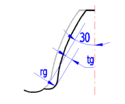
YSg = 1.3 * YS / (1.3 - 0.6 * (tg / rg)0.5) ... [ (tg / rg)0.5 < 2.0 ]
Yb = 1 - eb * b / 120 ... [if b > 30; b = 30]
external gears
YB = 1.0 ... [sR / ht >= 1.2]
YB = 1.15 * ln(8.324 * mn / sR) ... [0.5 < sR
/ ht < 1.2]
internal gears
YB = 1.0 ... [sR / mn >= 3.5]
YB = 1.6 * ln(2.242 * ht / sR) ... [1.75 < sR
/ mn < 3.5]
YDT = 1.0 ... [ean
<= 2.05] or [accuracy grade > 4]
YDT = -0.666 * ean
+ 2.366 ... [2.05 < ean
<= 2.5] and [accuracy grade <= 4]
YDT = 0.7 ... [ean
> 2.5] and [accuracy grade <= 4]
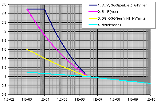
X axis ... number of cycles
Y axis ... YNT
YdrelT = Yd
/ YdT = (1 + (r'
* c*)0.5)
/ (1 + (r'
* cT*)0.5)
c* =
cP*
* (1 + 2 * qs)
cP*
= 1 / 5 = 0.2
cT*
= cP*
* (1 + 2 * 2.5)
Material: GG [σB=150MPa], GG, GGG(ferr.)[σB=300MPa]
r'
= 0.31
Material: NT, NV
r'
= 0.1005
Material: St, V, GTS, GGG(perl.), GGG(bai.)
r'
=
MAX(MIN(13100 / Rp0.2(2.1) - (MAX(600;Rp0.2)-600)(0.35)
/ 1600;0.32);0.0014)
Material: Eh, IF(root)
r'
= 0.003
Material: St, V, GGG(perl.), GGG(bai.)
YdrelT = (1 + 0.82 * (YS
- 1) * (300 / σ0.2)(1/4)) / (1 + 0.82 * (300 / σ0.2)(1/4))
Material: Eh, IF, IF(root)
YdrelT = 0.44 * YS +
0.12
Material: NT, NV
YdrelT = 0.20 * YS +
0.60
Material: GTS
YdrelT = 0.075 * YS +
0.85
Material: GG, GGG(ferr.)
YdrelT = 1.0
Rz < 1 mm
Material: V, GGG(perl.), GGG(bai.), Eh, IF
YRrelT = 1.12
Material: St
YRrelT = 1.07
Material: GG, GGG(ferr.), NT, NV
YRrelT = 1.025
1mm < Rz < 40 mm
Material: V, GGG(perl.), GGG(bai.), Eh, IF
YRrelT = 1.674 - 0.529 * (Rz + 1)0.1
Material: St
YRrelT = 5.306 - 4.203 * (Rz + 1)0.01
Material: GG, GGG(ferr.), NT, NV
YRrelT = 4.299 - 3.256 * (Rz + 1)0.0058
YRrelT = 1.0
YX = 1.0 ... All materials for static stress
YX ... Material: St, St(cast),
V, V(cast), GGG(perl.), GGG(bai.), GTS(perl.)
YX = 1.0
... [ mn <= 5 ]
YX = 1.03 - 0.006 * mn
... [ 5 < mn < 30 ]
YX = 0.85 ... [ mn >=
30 ]
YX ... Material:
Eh, IF(root), NT, NV, NT(nitr.), NV(nitr.), NV(nitrocar.)
YX = 1.0
... [ mn <= 5 ]
YX = 1.05 - 0.01 * mn
... [ 5 < mn < 25 ]
YX = 0.80 ... [ mn >=
25 ]
YX ... Material: GG,
GGG(ferr.)
YX = 1.0
... [ mn <= 5 ]
YX = 1.075 - 0.015 * mn
... [ 5 < mn < 25 ]
YX = 0.70 ... [ mn >=
25 ]
This part of ISO 6336 describes contact and tooth-root stresses, and gives numerical values for both limit stress numbers. It specifies requirements for material quality and heat treatment and comments on their influences on both limit stress numbers.
The allowable stress numbers, σH lim, and the nominal stress numbers, σF lim, can be calculated by the following equation:
a) σHlim = A * x + B
b) σFlim = A * x + B
where x is the surface hardness HBW or HV and A, B are constants
The three material quality grades ML, MQ and ME, stand in relationship to
- ML stands for modest demands on the material quality and on the material heat
treatment process during gear manufacture.
- MQ stands for requirements that can be met by experienced manufacturers at
moderate cost.
- ME represents requirements that must be realized when a high degree of
operating reliability is required
In this calculation, except σHlim and σFlim, are proposed other material
parameters that are necessary for calculating the gearing. The values of Ro, E
and Poisson constant are commonly available. For the proposal of the tensile strength Rm
and yield strength Rp0.2 was used information from the ISO 1265 and specialized
literature. Parameters for the time-strength curves were obtained from ISO6336-2
and 3. These curves can be seen in a small graph in the calculation.
All calculated values are design and based on empirical experience. The exact
values for a concrete material you can obtain from your manufacturer or from
material tests.
Values HB for HB<=450 steel ball, HB>450 carbide ball
Values HB used recalculation HB=HV-HV/20
Values HRC used recalculation HRC=(100*HV-14500)/(HV+223)
Kv = (C / (C + vt))−B
C = 50 + 56 * (1.0 − B) ... [ 6 ≤ Av ≤ 12 ]
B = 0.25 * (Av − 5.0)0.667
vt max = [C + (14 − Av)]2
The empirical guidance values from table B.1 ISO 6336-6 are used.
Cp = (1 / p
* (((1 - mP2)
/ EP) + ((1 - mG2) /
EG)))0.5 ... [lb/in2]0.5
mP and mG
is Poisson’s ratio for pinion and gear, respectively; EP and EG is
modulus of elasticity for pinion and gear [lb/in2].
Cf = 1.0
Through hardened gears
CH = 1.0 + A * (mG - 1.0)
A = 0.00898 *(HBP / HBG) - 0.00829
HBP is pinion Brinell hardness number [HB]; HBG is gear Brinell hardness
number,[HB].
This equation is valid for the range 1.2 ≤ HBP / HBG ≤ 1.7 For HBP / HBG < 1.2,
A = 0.0 HBP / HBG > 1.7, A = 0.00698
Surface hardened/through hardened values
CH = 1.0 + B * (450 - HBG)
B = 0.00075 * (2.71828)-0.0112 * (fp)
fp is surface finish of pinion, microinches, Ra
if fp>64 ... CH = 1.0
Km = f (Cmf, Cmt)
Km = Cmf
Cmf = 1.0 + Cmc * (Cpf *
Cpm + Cma * Ce)
Cmc is 1.0 for gear with unmodified leads; Cmc is 0.8 for gear with leads
properly modified by crowning or lead correction.
Cpf = F / (10 * d) − 0.025 ... [F<=1.0]
Cpf = F / (10 * d) − 0.0375 + 0.0125 * F ... [1.0<F<=17.0]
Cpf = F / (10 * d) − 0.1109 + 0.0207 * F − 0.000228 * F2 ...
[17.0<F<=40.0]
Cpm = 1.0 ... [S1 / S < 0.175]
Cpm = 1.1 ... [S1 / S >= 0.175]
Cma = A + B * F + C * F2
| A | B | C | |
| 1…Open gearing | 0.247 | 0.0167 | -0.0000765 |
| 2…Commercial enclosed gearboxes | 0.127 | 0.0158 | -0.0001093 |
| 3…Precision enclosed gearbox | 0.0675 | 0.0128 | -0.0000926 |
| 4…Extra precision enclosed gearbox | 0.038 | 0.0102 | -0.0000822 |
Ce = 0.8 ... [gearing is adjusted at assembly; gearing is
improved by lapping]
Ce = 1.0 ... [for all other conditions]
KR = 1.50 [Fewer than one failure in 10 000]
KR = 1.25 [Fewer than one failure in 1000]
KR = 1.00 [Fewer than one failure in 100]
KR = 0.85 [Fewer than one failure in 10]
KR = 0.70 [Fewer than one failure in 2]
KB = 1.6 * ln(2.242 / mB) ... [for mB<1.2]
KB = 1.0 ... [for mB>=1.2]
mB = tR / ht
tR is gear rimthickness below the tooth root
[in]; ht is gear
tooth whole depth [in]
The contact stress number formula for gear teeth is:
sc = Cp (Wt * Ko * Kv * Ks * Km * Cf / (d * F * I))0.5
Allowable contact stress number
The relation of calculated contact stress number to allowable contact stress
number is:
sc ≤ (sac * ZN * CH) / (KT * SH * KR)
Pitting resistance power rating
The pitting resistance power rating is:
Pac = (p * np * F / 396 000) * I / (Ko * Kv * Ks * Km * Cf) * ((d * sac * ZN CH) / (Cp * SH * KT * KR))2
SH = sac / sc * (ZN * CH) / (KT * KR)
The fundamental formula for bending stress number in a gear tooth is:
st = Wt * Ko * Kv * Ks * (Pd * Km * KB / (F * J))
Allowable bending stress number
The relation of calculated bending stress number to allowable bending stress
number is:
st ≤ (sat * YN) / (SF * KT * KR)
Bending strength power rating
The bending strength power rating is:
Pat = (p * np * F / 396 000) * (F * J) / (Ko * Kv * Pd * Ks * Km * KB) * (sat * YN) / (SF * KT * KR)
SF = sat / st * YN / (KT * KR)
Transmitted tangential load
Wt = 33000 * P / vt = 2 * T / d = 396000 * P / (p
* np * d)
P is transmitted power [hp];
T is transmitted pinion torque [lb*in];
vt is pitch line velocity at operating pitch diameter,
[ft/min]
vt = p
* np * d / 12
This part of ANSI / AGMA 2001-D04 describes the allowable stress numbers sac and sat, for pitting resistance and bending strength.
Allowable stress numbers in this standard are determined or estimated from
laboratory tests and accumulated field experiences. They
are based on unity overload factor, 10 million stress cycles, unidirectional
loading and 99 percent reliability. For service life other than 10
million cycles, the allowable stress numbers are adjusted by the use of stress
cycle factors YN and ZN
The allowable stress numbers sac and sat can be calculated by the following equation:
a) sac = A * x + B
b) sat = A * x + B
where x is the surface hardness HBW and A, B are constants
These requirements are specified in this standard and are divided in three material quality grades 1,2 an 3.
In this calculation, except sac and sat, are proposed other material parameters that are necessary for calculating the gearing. The values of p, E and Poisson constant are commonly available. For the proposal of the tensile strength Rm and yield strength Rp0.2 was used information from the ISO 1265 and specialized literature. All calculated values are design and based on empirical experience. The exact values for a concrete material you can obtain from your manufacturer or from material tests.
Values HB for HB<=450 steel ball, HB>450 carbide ball
Values HB used recalculation HB=HV-HV/20
Values HRC used recalculation HRC=(100*HV-14500)/(HV+223)
^