The program is intended for a design of a flywheel, its analysis, and determination of dimensions. It also allows to solve a crank mechanism and to determine parameters of asynchronous motors.
The program solves:
1. Design of a moment of inertia for a selected machine
2. Design of flywheel dimensions based on a required moment of inertia
3. Calculation of a moment of inertia based on dimensions of a flywheel
4. Calculation of a moment of inertia of masses with different revolutions (reduced moment of inertia)
5. Calculation of a stress in rotating rings
6. Calculation of gyroscopic moment
7. Calculation of a moment of inertia from a load diagram and a required run unevenness
8. Calculation of coefficient of fluctuation of speed
9. Design of a flywheel in connection with a motor
10. Selection and calculation of parameters of approximately 1200 asynchronous electric motors
11. Crank mechanism solution
The calculations use data, procedures, algorithms and information from literature, standards, and company catalogues.
[1] Strojně technická příručka (Svatopluk Černoch)
[2] Shigley’s Mechanical Engineering Design
[3] Strojírenská
příručka (1992)
[4]
Machinery’s Handbook
(26th Edition)
Standards: EN 60034-30-1 :20 14
Rotating electrical machines — Part 30-1: Efficiency classes of line operated AC
motors (IE code)
Machines Olectriques tournantes — Partie 30-1: Classes de rendement pour les
moteurs a courant alternatif alimentés par le réseau (Code IE)
Drehende elektrische Maschinen — Teil 30-1: Wirkungrad-Klassifizierung von
netzgespeisten Drehstrommotoren (IE-Code)
Company cataloques:Siemens, ABB Automation Products
Download.
Purchase, Price list.
Information on the syntax and control of the calculation can be found in the document "Control, structure and syntax of calculations".
Information on the purpose, use and control of the paragraph "Information on the project" can be found in the document "Information on the project".
The following formulas are used in the calculations.
I = C * Pw / (n³ * δ)
C ... Güldner's constant, which determines the type of machine
Pw ... Machine power
n ... Apeed [/s]
δ ... Coefficient of fluctuation of speed recommended for the machine type
δ = (ωmax - ωmin) / ωm
ωmax ... Maximum angular speed
ωmin ... Minimum angular speed
ωm = (ωmax - ωmin) / 2 ... Mean angular velocity
I = 0.5 * Ro * Pi * b * (R⁴ - r⁴)
Ro ... Density
b ..... Disc width
R ..... Outer radius
r ...... Inner radius
If there are masses in the system rotating at different speeds (transmission ratio), it is necessary to convert their moment of inertia to the moment of inertia of the flywheel.
Ired = Σ I(i) * (n / n(i))²
I(i) ... The moment of inertia of a mass rotating at a different speed than the
flywheel
n ...... Flywheel speed
n(i) ... The rotational moment of a mass rotating at a different speed than the
flywheel
The reduced moments of inertia can then be added directly to find the total
moment of inertia of the system.
σt = Ro * ω² * ((3 + ny) /8 ) * (r² + R² + r² * R² / rx² - (1 + 3 * ny) / (3 + ny) * rx²)
Ro ... Density
ω ... Angular velocity
ny ... Poisson's constant
R ..... Outer radius
r ...... Inner radius
rx .... The radius at which the stress is calculated
Time
t = (0.1047197533 * (n2 - n1) * I) / T
Energy
E = 0.005483 * I * (n2² - n1²)
T ... Torque
I .... Moment of inertia
n1,n2 ... Speed
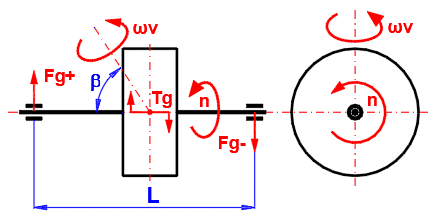
Tg = Pi * n * I * ωv / 30 * sin(β)
I .... Moment of inertia of the flywheel
n ... Flywheel speed [/min]
β ... Angle of the flywheel rotation axis
ωv ... Angular speed of rotation of the flywheel
In motors and machines where rotary motion is converted to rectilinear and in machines where there is no constant load, torque fluctuation occurs. There is no constant balance between the acting moments (driving, driven, inertial forces, passive resistances). This results in a change in angular velocity during the work cycle. To reduce this inequality, a flywheel is used as an energy accumulator, which accumulates the energy in the event of an excess of torque, and releases it in the event of a lack of it.
A large number of machines have a torque curve that cannot be simply
described analytically. Therefore, numerical integration methods are used for
the solution. The torque sequence on the left side is defined by the torque
table in dependence on the rotation of the flywheel. The moment on the right
side can be:
A. Constant
B. Dependent on the speed of the flywheel (electric motor, generator)
C. Or it can be defined by a custom table or function
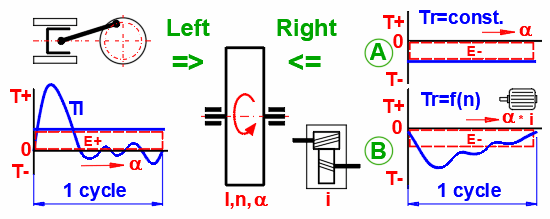

Ired … Reduced moment of inertia of all rotating masses
ω1, ω2 … Angular velocity at the beginning and end of the
work cycle
a … Angle of rotation of the flywheel during the
working cycle
da … Elementary rotation of the flywheel
ΣTx ... The sum of all acting moments (Driving, driven, inertial forces, passive
resistances)
The goal is to solve the course of the acting moment on the right side so that it meets the conditions (e.g. the characteristics of an asynchronous electric motor) and at the same time the sum of the energies of the left and right sides is zero (ω1 = ω2).
An example can be the dependence of the torque of a single-cylinder four-stroke internal combustion engine on the angle of rotation of the crank (see picture).
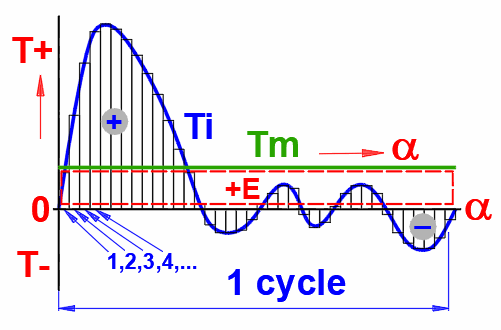
The calculation takes place in the following steps:
Tmid(j) = (Ti(j) + Ti(j+1)) / 2 ... <j = 1 ... n>
dE(j) = Tmid(j) * da ... <j = 1 ... n> ... for each segment 1,2,3,4.....
Where:
da = a / n
dEsum = ΣdE(j) ... <j = 1 ... n>
Tm = dEsum / a
ω(j+1) = (ω(j) + 2 * dE'(j) / I)^0.5
where:
dE'(j) =
(Tmid(j)
- Tm) * da
I ... The moment of inertia of the flywheel and the attached rotating
masses
ωmin = MIN (ω(j)) ... <j = 1 ... n+1>
ωmax = MAX (ω(j)) ... <j = 1 ... n+1>
ωm = (ωmin + ωmax) / 2
δ = (ωmax - ωmin) / ωm
Alternatively, calculate the moment of inertia from the coefficient of
fluctuation of speed.
I = dEsum' / (δ * ωm^2)
where:
dEsum' = ΣdE'(j) ... <j = 1 ... n>

If, for example, an asynchronous motor (generator) is used instead of a constant value Tm, the torque of which is dependent on the speed, the torque value, which corresponds to the revolutions of the flywheel for each step, is gradually used. The entire model is recalculated with each change.
In dependence on the input data (motor power, moment of inertia, degree of non-uniformity, etc.) the solution converges to equilibrium usually in the matter of several tens of iterations.
Analysis allows you to solve/examine:
- Accurate calculation of moment of inertia for the required degree of run
unevenness
- Calculation of run unevenness for the specified moment of inertia
- Calculation of the course of revolutions, moments, energies, and powers
- Suitability check of the selected motor/generator (speed and power)
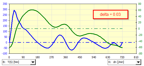
An example of analysis of an asynchronous generator coupled to a single-cylinder gasoline engine for various non-uniformities of the delta run:
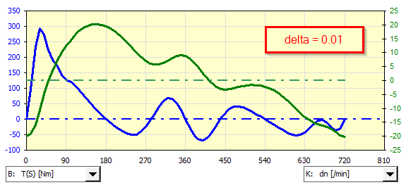
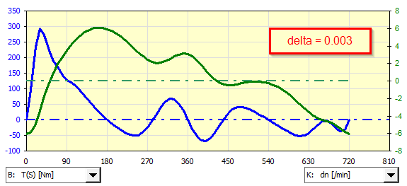
If it is necessary to use a non-predefined asynchronous motor (generator), its characteristic can be defined manually and used during iteration.
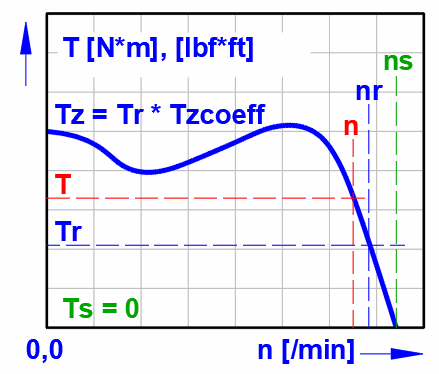
In the field of machine and equipment drives, an asynchronous motor (induction motor) is most often used. For this motor, the torque changes with the revolutions (linearly in the working range). A table of parameters for any motor was generated by comparing numerous manufacturers’ catalogs.
In this chapter, you will find the parameters of the selected motor (including estimation of weight, efficiency and moment of inertia), power and moment for other than nominal speeds.
Synchronous speed
ns = 2 * f * 60 / p
f ... Frequency of the power grid (60 Hz USA, Canada..., 50 Hz Europe)
p ... Number of motor poles
Rated speed (Asynchronous speed)
nr = (1 - s / 100) * ns
s ... Motor slip [%]motor
Rated torque
Tr = Pr * 9550 / nr
Pr ... rated power
Pull-up torque
Tz = Tr * Tzcoeff
Tzcoeff ... Pull-up torque coefficient
For small motors (≤ 30 kW) the value is 2.5-3, for medium motors 2-2.5, for
large motors 1-1.5.
A crank mechanism is often used to convert rectilinear to rotary motion (and vice versa), usually in combination with a flywheel. For the design of the flywheel, it is then necessary to know the course of the moment. To calculate the course of the moment, it is necessary to know the course of the loading force (Fp), the dimensions (L,R), the revolutions (n) and the weight of the individual parts (mp, m).
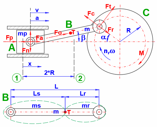
The following formulas are used in the calculation to determine the course of the moment during crankshaft rotation. The meaning of the individual variables is shown in the figure.
β = asin(R / L * sin(α))
λ = R / L
x = R * (1 - cos(α) + λ / 2 * sin(α)^2) ... Distance from the top pivot (1)
v = R * ω * (sin(α) + λ * sin(α) * cos(α))
a = R * ω^2 * (cos(α) + λ * cos(2 * α))
ω =2 * Pi * n / 60
ms = Lr / L * m
mr = Ls / L * m
Fa = (m + ms) * a ... Acceleration/Deceleration of straight moving parts
Fn = Fp * tan(β) + Fa * tan(β)
Ft = Fp * (sin(α) + λ * sin(2 * α) + Fa * (sin(α) + λ * sin(2 * α)
Fo = Fp / cos(β)
Fr = Fo * cos(α + β)
Fc = mr * R * ω^2 ... Centrifugal force of connecting rod on crank
M = R * Ft ... Moment from load force Fp and acceleration/deceleration force Fa
The calculation is intended for a quick flywheel design and its analysis.
Aproximate design, paragraph [2]:
- Approximate design of a moment of inertia of a flywheel according to a type
and parameters of the machine
- Design of flywheel dimensions based on a moment of inertia
- Voltage control, max. speed control, gyroscopic moment control
Detailed analysis, paragraph [3]:
If you know the torque curve of the machine for which you want to design a
flywheel, use the table to define the curve. You will quickly find out the
necessary moment of inertia for the required run unevenness, or the run
unevenness for the entered moment of inertia (Analysis A).
Use Analysis B, if you need to solve a pair of machine x electric motor (machine x generator).
In this paragraph you set the units of calculation.
Select the desired system of calculation units in the list box. After switching over the units, all values will be changed immediately.
Type the value you want to convert into the input box on the left. Select source units and target units on the right.
- Approximate design of a moment of inertia for a selected type of machine
- Design of flywheel dimensions based on moment of inertia
- Calculation of a moment of inertia from dimensions of a flywheel
- Calculation of energy of a rotating flywheel and calculation of the maximum
voltage
- Recalculation of moments of inertia of masses rotating at different speeds
- Calculation of a time necessary to to spin the flywheel
- Calculation of gyroscopic moment and forces
It is possible to estimate the necessary moment of inertia for a flywheel
based on the type of machine, the power, and the speed of the flywheel.
Select the type of machine (and thus the constant C that characterizes it),
enter the nominal power, the speed of the flywheel, and the required degree of
unevenness.
The following values are recommended for different areas of machinery.
Type of machine / coefficient of fluctuation of speed (δ)
Crushing machines ..... 0.200
Electrical machines ..... 0.003
Electrical machines (direct drive) ..... 0.002
Engines with belt transmission ..... 0.030
Gear wheel transmission ..... 0.020
Hammering machines ..... 0.200
Pumping machines ..... 0.030 to 0.05
Machine tools ..... 0.030
Paper making ..... 0.015
Textile and weaving machines ..... 0.010 - 0.025
Punching. shearing and power presses ..... 0.10 - 0.15
Spinning machinery ..... 0.10 - 0.020
Rolling mills and mining machines ..... 0.025
DC generators ..... 0.006 - 0.013
AC generators ..... 0.003 - 0.015
Vehicle internal combustion engines ..... 0.003 - 0.006
Based on the required moment of inertia, you can design the dimensions of the
flywheel ring.
Enter the required moment of inertia, the density of the material used, the
ratio of the width and height of the flywheel rim, and the required inner
diameter.
The moment of inertia from the reference design is used. If you want to enter a custom value, uncheck the checkbox on the right.
Steel 7800 [kg/m³]; 487 [lb/ft³]
Cast iron 7200 [kg/m³]; 450 [lb/ft³]
Bronze 8800 [kg/m³]; 550 [lb/ft³]
Aluminum 2700 [kg/m³]; 168 [lb/ft³]
Hardwood 680 [kg/m³]; 42 [lb/ft³]
The greatest stress in a rotating ring is the tangential stress on its inner
side.
Enter the maximum allowable stress and Poisson's constant of the material.
Enter RPM. The green field shows the maximum speed value for the entered maximum
permissible voltage.
Pressing the "==>" button transferrs the calculated design values into the
selected row of the table.
Cast iron ... < 8-10 MPa (1.16 - 1.45
kpsi)
Casting steel ... < 100 MPa (14.5 kpsi)
Steel ... 0.27-0.30
Cast iron ... 0.21-0.26
Aluminium alloys ... 0.33
Copper ... 0.33
Magnesium ... 0.35
Titanium ... 0.34
The revolutions value from line [2.5] is used as the default. To enter your own values, uncheck the checkbox to the right.
The calculated stress should be less than the maximum allowed [2.19].
You can define up to 12 different rings in the table and thus assemble a more
complex flywheel shape, or recalculate masses with different rotation speeds.
The "Clear" button clears the dimensional values in the entire table, except for
the first row.
The "V" button transfers the value from the first line to the others.
The "min/max" button fills in the outer/inner diameter of the ring to calculate
the stress on the outer/inner diameter.
Column labels
Number: Multiplies calculated values (multiple identical rotating masses)
a: Displacement of the ring (cylinder) in the graph in the X axis
D, d, b: Ring (cylinder) dimensions
Ro: Density
ny: Poisson's constant
n: RPM
ω: Angular velocity
rg: Radius of inertia
m: Mass
I: Moment of inertia
Ired: Reduced moment of inertia (recalculated via revolutions to the first line)
Ek: Kinetic energy of the rotating disc
dx: The ratio for which the tangential stress will be calculated
σt: Tangential stress
Calculation of the energy and time required to spin the flywheel with the
specified moment of inertia to the required speed.
The values are preset from the table above. To enter your own values uncheck the
checkbox to the right.
When the flywheel rotates around an axis other than the axis of rotation, a
gyroscopic moment is generated. For larger moments of inertia and higher speeds,
it can be significant and must be taken into account in the calculations.
The preset values are from the table above, after unchecking the checkbox you
can enter your own values.
Objects from table [2.25] are plotted in the graph.
The "a" coordinate in the table defines the displacement in the X axis.
In motors and machines where rotary motion is converted to rectilinear and in machines where there is no constant load, torque fluctuation occurs. There is no constant balance between the acting moments (driving, driven, inertial forces, passive resistances). This results in a change in angular velocity during the work cycle. To reduce this inequality, a flywheel is used as an energy accumulator, which accumulates the energy in the event of an excess of torque, and releases it in the event of a lack of it.
A large number of machines have a torque curve that cannot be simply
described analytically. Therefore, numerical integration methods are used for
the solution. The torque sequence on the left side is defined by the torque
table in dependence on the rotation of the flywheel. The moment on the right
side can be:
A. Constant
B. Dependent on the speed of the flywheel (electric motor, generator)
C. Or it can be defined by a custom table or function
!!! Proceed as follows during the analysis !!!
1. Fill in the table [3.45] with the course of the moment of the analyzed
machine
2. Enter flywheel parameters [3.1]
3. Run analysis A or B or C
4. Review the results of the analysis on lines [3.28 - 3.42], in the table
[3.45] and in the graphs
You can either enter the moment of inertia and the result of the analysis will be the degree of running unevenness, or by unchecking the checkbox on the right, you can enter the degree of running unevenness, and the result will be the corresponding moment of inertia.
The following values are recommended for different areas of machinery.
Type of machine / coefficient of fluctuation of speed (δ)
Crushing machines ..... 0.200
Electrical machines ..... 0.003
Electrical machines (direct drive) ..... 0.002
Engines with belt transmission ..... 0.030
Gear wheel transmission ..... 0.020
Hammering machines ..... 0.200
Pumping machines ..... 0.030 to 0.05
Machine tools ..... 0.030
Paper making ..... 0.015
Textile and weaving machines ..... 0.010 - 0.025
Punching. shearing and power presses ..... 0.10 - 0.15
Spinning machinery ..... 0.10 - 0.020
Rolling mills and mining machines ..... 0.025
DC generators ..... 0.006 - 0.013
AC generators ..... 0.003 - 0.015
Vehicle internal combustion engines ..... 0.003 - 0.006
Enter the required flywheel speed.
Basic analysis, applicable in all cases.
In this calculation, the increase (decrease) in energy is calculated from the moment curve on the left. From the calculated energy, a constant moment is determined, which must act on the right side so that the sum of the energies is zero.
On the basis of the acting moments (left + right side), the course of the angular velocity (revolutions) and thus the unevenness of the run for the specified moment of inertia of the flywheel is obtained. Or the moment of inertia of the flywheel for a given degree of unevenness is determined.
Power + (power input -) device on the right, to generate the required constant torque (mean torque Tm).
Special case analysis where an asynchronous motor/generator (right side) is connected to the device (left side).
In addition to the condition of the sum of the energies of the left and right sides is equal to zero, it is also necessary to observe that the torque of the electric motor/generator is a function of the flywheel revolutions.
In this calculation, the motor torque is used repeatedly (see the number of iteration steps) according to the current flywheel revolutions, while the entire cycle is recalculated after each individual change. After each iteration step, the flywheel speed at the beginning of the cycle is adjusted accordingly. Most of the time, the whole model converges fast enough for smaller tens of iteration steps.
Select a motor from the list.
Motors are listed in the form of “<Synchronous speed> / <number of poles> ... <frequency of the electrical system>"
Recommended motor (generator) power interval estimated from the torque curve on the left.
Enter the motor power. Approximate motor parameters (nr, Tz, etc.) will be proposed based on the power.
Catalog values of motor manufacturers:
kW (50Hz):
0.06; 0.09; 0.12; 0.18; 0.25; 0.37; 0.55; 0.75; 1.1; 1.5; 2.2; 3; 3.7; 4; 5.5;
7.5; 9; 11; 15; 18.5; 22; 30; 37; 45; 55; 75; 90; 110; 132; 160; 200; 225; 250;
280; 315; 355; 400; 450; 500; 560; 630; 710; 800; 900; 1000
HP (60Hz):
0.25; 0.33; 0.5; 0.75; 1; 1.5; 2; 3; 4; 5; 5.5; 7.5; 10; 12; 15; 20; 25; 30; 40;
50; 60; 75; 100; 120; 150; 180; 210; 270; 300; 335; 375; 420; 475; 530; 600;
670; 750; 850; 950
The motor can also function as an electric current generator (Exceeding synchronous speed and consumption of mechanical energy).
Select from the list to set the type of behavior.
Set according to the selected motor type. At these speeds there is zero torque.
The rated speed and starting torque coefficient are directly given for the
specific motor. The green field contains an approximate value for the given
motor type and power.
To enter your own values (nr, Tzcoeff), uncheck the checkbox on the right. It is
thus possible to set the motor characteristics exactly according to the catalog
of a specific manufacturer.
For small motors (≤ 30 kW) the value is 2.5-3, for medium 2-2.5, for large 1-1.5.
The first number indicates the approximate moment of inertia of the selected motor. The second number is multiplied by the square of the gear ratio "i" from the next line. It is thus possible to directly compare or subtract the value from the moment of inertia of the flywheel.
The gear ratio is set automatically. It is estimated so that the required mean flywheel speed [3.4] approaches the calculated one.
To enter your own values, uncheck the checkbox on the right. This can be convenient if you need to set, for example, a gear ratio i=1 (direct flywheel drive).
Iteration
Set the number of iteration steps. After each step, the table and graph are
refreshed, thus it is possible to follow the gradual changes.
Sensitivity
The sensitivity determines the amount of change in the initial speed of the
flywheel before each step.
The larger the value, the larger the change and the faster the convergence. On
the other hand, too large a value can lead to oscillation or non-functional
solution.
The letter indicates for which analysis (A, B, C) the results are shown.
The sum of the energies from the left side and from the right side of the flywheel. For steady operation (flywheel speeds at the beginning and end of the duty cycle are the same), the sum must be close to zero. The percentages express the deviation of the sum from the input energy (left side). A red value means that the deviation is greater than 1%.
Summary results of the flywheel calculation.
The default setting of the average flywheel speed for the calculation and the angular velocity calculated from them.
Analysis A: The value from the required revolutions is set in the cell [3.4]
Analysis B, C: The corrected value from the previous step is moved to the cell
after each iteration step (green cell).
Before starting the analysis, it is necessary to fill in the torque curve of the machine that we want to analyze (left side).
Define the flywheel load in the first two columns A, B of the table.
1) In column A, enter consecutively the angles for which you will define the
moment acting on the flywheel (left side).
- Values must be in a continuous row without empty lines
- Angles must be entered in ascending order
- The difference between subsequent angles may not be regular. This can be used
for example during a step change in torque (the difference between the
subsequent angles is small)
2) Enter the torque acting on the flywheel in column B. A positive value speeds up the flywheel; a negative value slows the flywheel down.
It is necessary to enter the number of valid rows of the table (those that
will be included into the analysis).
If you want to enter a value other than the suggested one (green cell), uncheck
the checkbox.
The suggested value follows the first empty cell in column B.
You have defined the moment load in column A,B (left side) of the table. The other columns are the result of the selected analysis.
α: The angle of rotation of the flywheel for which the moment is defined in column B. By pressing the "+Δ" button, the entire column is filled so that each subsequent value is increased by the difference between the second and the first line.
Tl: Torque curve of the machine you want to analyze (left side)
Ti=Tl+Tr: Course of the moment acting on the flywheel. Sum of the left and right sides.
Tr=Tm: The torque curve that balances the torque from column B
Analysis A: Constant, Tr = Tm
Analysis B: Iteration, Tr = Te * i
Analysis C: User Defined Moment
ne: Motor speed dependent on flywheel speed. ne = n * i
Te: Motor torque. It depends on the speed ne.
Pwe: Motor power.
+-dE: Energy that is supplied (+) / removed (-) to the flywheel between the current and the next angle of rotation (column A)
E: Current value of kinetic energy at the relevant angle of rotation of the flywhee.
n: RPM for the respective angle of rotation of the flywheel
dn: Difference between current and target revolutions
ω: Angular velocity at the respective roll angle
dω: Fluctuation of angular velocity. The difference between the current speed for the respective roll angle and the mean value
Pw: Flywheel power for a given angle of rotation
Torque and power curve of the electric motor / generator
Axis: X - RPM, (red vertical = ns)
Axis: Y
Blue: Torque [Nm; lbf*ft] + work area
Green: Power [kWh; HP] + work area
Moments and speed
Axis: X - Spin the flywheel
Axis: Y
Light black: Moment left side [Nm; lbf*ft]
Light red: Moment right side [Nm; lbf*ft]
Strong blue: Sum of moments [Nm; lbf*ft]
Strong green: flywheel speed [/min] (scale on the right)
Select the curves you want to display in the puldowns below the graph.
Axis: X - Spin the flywheel
The three columns on the left in the table can be used for user definition of
the moment (right side); for example in dependence on the speed of the flywheel.
Clicking the buttons "Tr=O(i)", "Tr=P(i)", or "Tr=Q(i)" sets the values from the
relevant column into column D (right side) and the same process as in the
analysis B will take place.
The number of repetitions and the sensitivity of the iteration are controlled by
the settings on line [3.25]
The cell below the button (named "_Const1", "_Const2", etc.) has no function and
can be used, for instance, as an input constant when defining a moment.
The first example shows the use of the following function
T = Const1 * cos (n / 3360)^0.33
T ... Moment (right side)
n ... Revolutions of the flywheel
Const1 ... Constant (in this case it expresses the magnitude of the moment at
zero revolutions)
The use of linear interpolation of the moment curve defined by individual points.
T = linear2 (n;T_User_nT)
T ... Moment (right side)
n ... Revolutions of the flywheel
T_User_nT ... The name of the table in which the curve of the sequence of the
pair of points is defined:
revolutions / torque
The table is defined on the "Tables" sheet
The example shows how to use the selected motor from paragraph 4.0
T = linear2(n * _Const3; T_4_nT) * _Const3
n ... Revolutions of the flywheel
T_4_nT ... The name of the table with the curve T=f(n) from paragraph 4.0
_Const3 … Gear ratio between flywheel and motor
In the field of machine and equipment drives, an asynchronous motor (induction motor) is most often used. For this motor, the torque changes with the revolutions (linearly in the working range). A table of parameters for any motor was generated by comparing numerous manufacturers’ catalogs.
In this chapter, you will find the parameters of the selected motor (including estimation of weight, efficiency and moment of inertia), power and moment for other than nominal speeds.
See paragraphs 3.12-3.19
Equally powerful motors, of course, differ in design, materials, purpose, and manufacturer. The values of weight and moment of inertia must therefore be taken as a reference value.
For more accurate calculations, it is advisable to know the efficiency of the motors and the corresponding markings.
Efficiency classes according to IEC 60034-30-1:2014
(IE = International Efficiency):
IE1 Standard efficiency (Standard Efficiency)
IE2 Increased efficiency (High Efficiency)
IE3 High efficiency (Premium Efficiency)
IE4 Very high efficiency (Super Premium Efficiency)
Comparison with another standard
IEC 60034-30-1 NEMA MG1 GB 18613-2012
===========================
IE4 Grade 1 (IE4)
IE3 Premium Efficient (60 Hz) Grade 2 (IE3)
IE2 Energy Efficient (60 Hz) Grade 3 (IE2)
Enter the speed for which you want to find the torque value.
The speed should be lower than ns. When the synchronous speed is exceeded, the
motor works as a generator (brakes and produces electric power) and the torque
is negative.
Moment and power curve of the electric motor (generator)
Axis: X - RPM
Axis: Y
Blue: Torque [Nm; lbf*ft]
Green: Power [kWh; HP]
Red: Moment for the specified speed
A crank mechanism is often used to convert rectilinear to rotary motion (and vice versa), usually in combination with a flywheel. For the design of the flywheel, it is then necessary to know the course of the moment. To calculate the course of the moment, it is necessary to know the course of the loading force (Fp), the dimensions (L,R), the revolutions (n) and the weight of the individual parts (mp, m).

Enter the crank mechanism parameters as shown on the picture.
Enter the mass of all parts that perform rectilinear motion (A).
Enter the total weight of the connecting rod (B).
Enter the connecting rod axis distance (B).
Enter the connecting rod center of gravity distance (B).
For motor, compressors ~ 0.7*L
For machine tools ~ 0.5*L
It is necessary to determine the mass of ms and mr.
To calculate the forces, the connecting rod is replaced by two mass points of mass ms (rectilinear movement) and mr (rotational movement), which act in the axes of the connecting rod.
Enter the crank radius (C).
The centrifugal force exerted by the connecting rod on the crank
Enter the crank rotation angle into the first column [α] of the table. By clicking the "+Δ" button, you can fill the entire column at once, so the difference between the first and second row is used for addition for each subsequent row.
Into the second column, enter the loading force [Fp] for each relevant angle
[α] of crank rotation.
It can be, for example, compressive force (compressor, motor) or machining force
(press).
The other columns show the values according to the picture (column C-M).
The last 4 columns contain selected values from the chart [5.16].
Blue - Total Moment (M)
Black thin - Moment from strength Fp
Red thin - Moment from acceleration/deceleration of moving parts Fa
Select which values you want to display in the graph on the right.
The x-axis is the rotation angle of the crank.
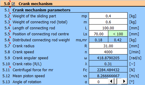
Combustion engine:
Bore: 72 mm => piston area: 0.004072 m^2 => Force Fp
Stroke: 62 mm => crank radius: 31 mm
Connecting rod length: 100 mm
Connecting rod center of gravity position: 70 mm
Piston weight: 0.4 kg
Weight of connecting rod: 0.6 kg
Required coefficient of fluctuation of speed: 0.01
Measured cylinder pressure for 4000/min in dependence on crank rotation.
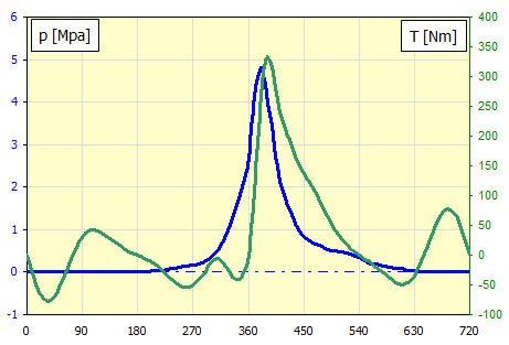
Define parameters of the crank mechanism in paragraph [5].
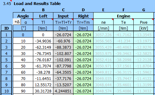
From pressure and boring, we obtain the force Fp for each angle of rotation of the connecting rod.
Enter the angle α [°] and the calculated force into the table.
| α | p | Fp | T | |
| ID | [°] | [Mpa] | [N] | [Nm] |
| 1 | 0 | 0 | 0 | 0 |
| 2 | 10 | 0 | 0 | -34.90 |
| 3 | 20 | 0 | 0 | -62.31 |
| 4 | 30 | 0 | 0 | -76.73 |
| 5 | 40 | 0 | 0 | -76.02 |
| 6 | 50 | 0 | 0 | -61.71 |
| 7 | 60 | 0 | 0 | -38.28 |
| 8 | 70 | 0 | 0 | -11.65 |
| 9 | 80 | 0 | 0 | 12.55 |
| 10 | 90 | 0 | 0 | 30.32 |
| 11 | 100 | 0 | 0 | 39.96 |
| 12 | 110 | 0 | 0 | 41.96 |
| 13 | 120 | 0 | 0 | 38.28 |
| 14 | 130 | 0 | 0 | 31.39 |
| 15 | 140 | 0 | 0 | 23.51 |
| 16 | 150 | 0 | 0 | 16.10 |
| 17 | 160 | 0 | 0 | 9.80 |
| 18 | 170 | 0 | 0 | 4.59 |
| 19 | 180 | 0 | 0 | 0.00 |
| 20 | 190 | 0.01 | 40 | -4.67 |
| 21 | 200 | 0.02 | 81 | -10.16 |
| 22 | 210 | 0.035 | 142 | -17.12 |
| 23 | 220 | 0.05 | 203 | -25.63 |
| 24 | 230 | 0.07 | 285 | -35.46 |
| 25 | 240 | 0.09 | 366 | -45.06 |
| 26 | 250 | 0.11 | 447 | -52.22 |
| 27 | 260 | 0.13 | 529 | -54.37 |
| 28 | 270 | 0.17 | 692 | -51.77 |
| 29 | 280 | 0.2 | 814 | -40.08 |
| 30 | 290 | 0.27 | 1099 | -27.16 |
| 31 | 300 | 0.35 | 1425 | -11.84 |
| 32 | 310 | 0.5 | 2035 | -5.88 |
| 33 | 320 | 0.75 | 3053 | -13.71 |
| 34 | 330 | 1.1 | 4478 | -29.94 |
| 35 | 340 | 1.5 | 6107 | -40.16 |
| 36 | 350 | 2 | 8143 | -35.70 |
| 37 | 360 | 2.7 | 10993 | 0.00 |
| 38 | 370 | 4.1 | 16693 | 109.82 |
| 39 | 380 | 4.8 | 19543 | 265.61 |
| 40 | 390 | 4.2 | 17100 | 330.63 |
| 41 | 400 | 3.2 | 13028 | 306.88 |
| 42 | 410 | 2.3 | 9364 | 249.28 |
| 43 | 420 | 1.75 | 7125 | 212.30 |
| 44 | 430 | 1.4 | 5700 | 189.61 |
| 45 | 440 | 1.05 | 4275 | 157.11 |
| 46 | 450 | 0.85 | 3460 | 137.58 |
| 47 | 460 | 0.75 | 3053 | 123.13 |
| 48 | 470 | 0.66 | 2687 | 103.64 |
| 49 | 480 | 0.6 | 2442 | 83.51 |
| 50 | 490 | 0.54 | 2198 | 62.78 |
| 51 | 500 | 0.5 | 2035 | 44.80 |
| 52 | 510 | 0.47 | 1913 | 29.83 |
| 53 | 520 | 0.45 | 1832 | 17.91 |
| 54 | 530 | 0.4 | 1628 | 8.00 |
| 55 | 540 | 0.35 | 1425 | 0.00 |
| 56 | 550 | 0.28 | 1140 | -6.98 |
| 57 | 560 | 0.2 | 814 | -13.41 |
| 58 | 570 | 0.18 | 732 | -21.35 |
| 59 | 580 | 0.15 | 610 | -29.89 |
| 60 | 590 | 0.12 | 488 | -38.36 |
| 61 | 600 | 0.1 | 407 | -45.82 |
| 62 | 610 | 0.08 | 325 | -49.42 |
| 63 | 620 | 0.05 | 203 | -45.49 |
| 64 | 630 | 0.04 | 162 | -35.34 |
| 65 | 640 | 0.02 | 81 | -15.29 |
| 66 | 650 | 0.01 | 40 | 10.23 |
| 67 | 660 | 0 | 0 | 38.28 |
| 68 | 670 | 0 | 0 | 61.71 |
| 69 | 680 | 0 | 0 | 76.02 |
| 70 | 690 | 0 | 0 | 76.73 |
| 71 | 700 | 0 | 0 | 62.31 |
| 72 | 710 | 0 | 0 | 34.90 |
| 73 | 720 | 0 | 0 | 0.00 |
This gives us the torque "T" for each angle.
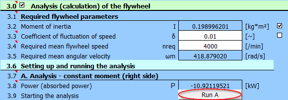
Required flywheel speed: 4000 /min
Required coefficient of fluctuation of speed: 0.01
Enter the angle and moment values in the table.
Enter the required coefficient of fluctuation of speed and the required flywheel speed [3.3, 3.4].
Press the "Run A" button to get calculated the necessary moment of inertia of the flywheel
The mean moment Tm is calculated. The moment is used as a constant load.
The results are shown immediately.
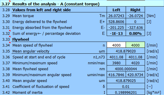
and wide chart options.
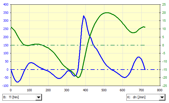
Here, for example, a graph of the motor torque and flywheel speed fluctuations.
The compressor is directly connected to the electric motor.
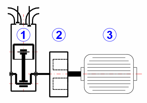
Compressor parameters
Piston diameter: 30 mm
Crank radius: 20 mm
Connecting rod length: 60 mm
Connecting rod center of gravity: 40 mm
Piston weight: 0.0286 kg
Connecting rod weight: 0.0572 kg
Speed: 3000 /min
Pressure curve in the compressor
Using the calculation in chapter [5.0], we obtain a graph and a table of moments from the course of the pressure and the parameters of the crank mechanism.
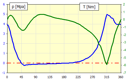
Table of moments.
| α | p | Fp | T | |
| ID | [°] | [MPa] | [N] | [Nm] |
| 1 | 0 | 3.95 | 279.20905 | 0 |
| 2 | 5 | 3.73184519 | 263.78859 | 0.41128229 |
| 3 | 10 | 3.080272 | 217.7316 | 0.56473025 |
| 4 | 15 | 2.48848056 | 175.90033 | 0.51340057 |
| 5 | 20 | 1.8080703 | 127.80496 | 0.19717123 |
| 6 | 25 | 1.31442485 | 92.911218 | -0.1398181 |
| 7 | 30 | 0.88581553 | 62.61461 | -0.5128466 |
| 8 | 35 | 0.48195088 | 34.067101 | -0.9203648 |
| 9 | 40 | 0.24031266 | 16.986701 | -1.1441075 |
| 10 | 45 | -0.00386229 | -0.2730089 | -1.3610845 |
| 11 | 50 | -0.15132193 | -10.696317 | -1.4133192 |
| 12 | 55 | -0.2362869 | -16.702137 | -1.3370272 |
| 13 | 60 | -0.1973125 | -13.947199 | -1.0312084 |
| 14 | 65 | -0.17359486 | -12.270698 | -0.7309989 |
| 15 | 70 | -0.15544822 | -10.987987 | -0.4378542 |
| 16 | 75 | -0.14173079 | -10.018359 | -0.1646365 |
| 17 | 80 | -0.13402177 | -9.4734403 | 0.0743766 |
| 18 | 85 | -0.12725568 | -8.9951742 | 0.27859924 |
| 19 | 90 | -0.120625 | -8.5264788 | 0.44357914 |
| 20 | 95 | -0.11418232 | -8.0710727 | 0.56667182 |
| 21 | 100 | -0.10797454 | -7.6322704 | 0.64817605 |
| 22 | 105 | -0.10204254 | -7.2129621 | 0.6908825 |
| 23 | 110 | -0.09642109 | -6.8156052 | 0.69948517 |
| 24 | 115 | -0.09113888 | -6.442228 | 0.67992578 |
| 25 | 120 | -0.08621875 | -6.0944443 | 0.63873909 |
| 26 | 125 | -0.08167802 | -5.7734789 | 0.58245836 |
| 27 | 130 | -0.07629347 | -5.3928677 | 0.51789065 |
| 28 | 135 | -0.07066924 | -4.995314 | 0.44958032 |
| 29 | 140 | -0.06565042 | -4.6405549 | 0.38115025 |
| 30 | 145 | -0.06123852 | -4.3286959 | 0.31567779 |
| 31 | 150 | -0.05743152 | -4.0595947 | 0.255123 |
| 32 | 155 | -0.054225 | -3.8329391 | 0.20044217 |
| 33 | 160 | -0.05161318 | -3.6483207 | 0.15175295 |
| 34 | 165 | -0.04589893 | -3.2444041 | 0.10900047 |
| 35 | 170 | -0.031494 | -2.2261796 | 0.07113676 |
| 36 | 175 | -0.02287093 | -1.6166511 | 0.03507503 |
| 37 | 180 | -0.02 | -1.4137167 | 4.9004E-17 |
| 38 | 185 | -0.01808604 | -1.2784271 | -0.035273 |
| 39 | 190 | -0.01233733 | -0.8720747 | -0.072752 |
| 40 | 195 | -0.00273405 | -0.1932585 | -0.1146239 |
| 41 | 200 | 0.01075453 | 0.7601932 | -0.1630174 |
| 42 | 205 | 0.02816664 | 1.9909827 | -0.2199255 |
| 43 | 210 | 0.04954345 | 3.5020199 | -0.2870821 |
| 44 | 215 | 0.07492346 | 5.2960275 | -0.3657929 |
| 45 | 220 | 0.10433615 | 7.3750878 | -0.4567331 |
| 46 | 225 | 0.13779491 | 9.7401485 | -0.5597348 |
| 47 | 230 | 0.17528981 | 12.390507 | -0.6735931 |
| 48 | 235 | 0.22517026 | 15.916348 | -0.8019252 |
| 49 | 240 | 0.29328125 | 20.73083 | -0.9484907 |
| 50 | 245 | 0.36708323 | 25.947585 | -1.101615 |
| 51 | 250 | 0.44631634 | 31.548243 | -1.256091 |
| 52 | 255 | 0.53063809 | 37.508596 | -1.4057648 |
| 53 | 260 | 0.61961808 | 43.798221 | -1.5438906 |
| 54 | 265 | 0.75455803 | 53.336564 | -1.7190622 |
| 55 | 270 | 0.91875 | 64.942611 | -1.9129609 |
| 56 | 275 | 1.11767048 | 79.003471 | -2.1337469 |
| 57 | 280 | 1.34076178 | 94.772866 | -2.3653236 |
| 58 | 285 | 1.60625075 | 113.53918 | -2.6341702 |
| 59 | 290 | 2.0520672 | 145.05208 | -3.1634106 |
| 60 | 295 | 2.38544142 | 168.61692 | -3.4715845 |
| 61 | 300 | 2.88710938 | 204.07774 | -4.0038618 |
| 62 | 305 | 3.57144831 | 252.4508 | -4.7586566 |
| 63 | 310 | 4.29339033 | 303.48188 | -5.4628709 |
| 64 | 315 | 4.94613771 | 349.62187 | -5.9198089 |
| 65 | 320 | 4.88350703 | 345.19477 | -5.2300665 |
| 66 | 325 | 4.81539388 | 340.38014 | -4.512448 |
| 67 | 330 | 4.62145388 | 326.67133 | -3.6522527 |
| 68 | 335 | 4.53092919 | 320.27251 | -2.9430483 |
| 69 | 340 | 4.19706534 | 296.67307 | -2.0759393 |
| 70 | 345 | 3.98461327 | 281.65572 | -1.4133487 |
| 71 | 350 | 3.95 | 279.20905 | -0.918416 |
| 72 | 355 | 3.95 | 279.20905 | -0.4560135 |
| 73 | 360 | 3.95 | 279.20905 | -1.277E-15 |
First, fill in the angles α and the corresponding moments in the table [3.43].
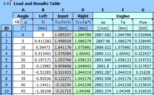
Enter the flywheel parameters:
Coefficient of fluctuation of speed: 0.01
Flywheel speed: 3000 /min

And the motor parameters:
Two-pole motor, ns: 3000 /min
Power from the help table: P=0.55kW
Set the gear ratio to: i=1.0
Run analysis B (several times in a row).
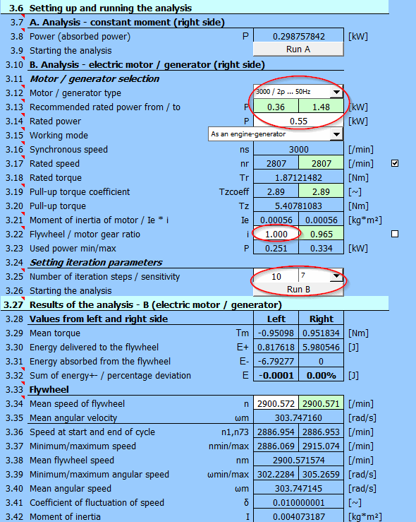
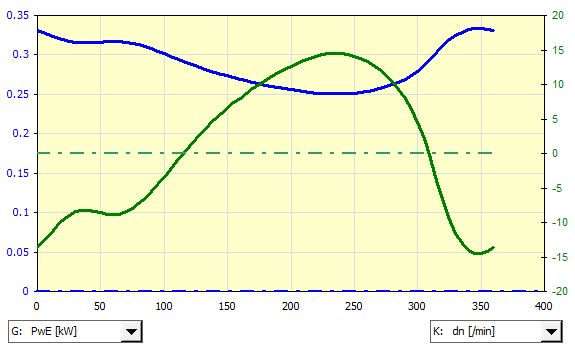
With a direct motor-compressor connection, it is not possible to achieve a synchronous speed of 3000 /min, because the asynchronous motor has zero power at synchronous speed. Due to the load, the speed thus stabilizes at a medium speed of 2900 rpm.
Graph of the motor performance and speed oscillation near the middle speed (2900 /min) during the work cycle:
The crank mechanism (1) is connected via a 5:1 gear (2) to the flywheel (3). The flywheel is driven via a belt transmission (4) by an asynchronous electric motor (5).
Task:
- Calculate the course of the loading moment T1
- Calculate the course of the loading moment T3
- Determine the moment of inertia of the flywheel for the specified run
unevenness
- Determine the required power of the electric motor
- Propose the dimensions of the flywheel
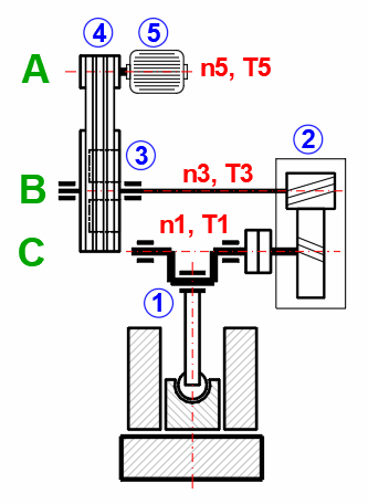
Required force: 10 tons
Working path: 20mm
Strokes per minute: 30
Weight of sliding part: 30 kg
Weight of the connecting rod: 30 kg
Connecting rod length 400mm
Connecting rod center of gravity: 200mm
Crank radius: 100mm
Resistance forces: 200N

In paragraph [5.0], define the parameters of the crank mechanism.
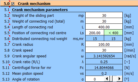
In the table, set the step to 5 degrees and enter the load values.
Against the loading force of 10 tons ~ 100000N, the forces of weight and
resistance (30kg+30kg+-200N)=800N (400N) act throughout the entire revolution.
100000N force acts from 325 degrees (22mm from top dead center).
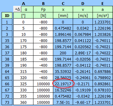
A detailed table with the entered data of the torque on the crank T1 and the
torque in front of the 5:1 gearbox T3.
| α | Fp | T1 | T3=T1/5 | |
| ID | [°] | [N] | [Nm] | [Nm] |
| 1 | 0 | -800 | 0 | 0 |
| 2 | 5 | -800 | -11.16588081 | -2.233176162 |
| 3 | 10 | -800 | -22.13614645 | -4.427229291 |
| 4 | 15 | -800 | -32.72117313 | -6.544234626 |
| 5 | 20 | -800 | -42.74303421 | -8.548606841 |
| 6 | 25 | -800 | -52.04065447 | -10.40813089 |
| 7 | 30 | -800 | -60.4741842 | -12.09483684 |
| 8 | 35 | -800 | -67.92841631 | -13.58568326 |
| 9 | 40 | -800 | -74.31513183 | -14.86302637 |
| 10 | 45 | -800 | -79.57432571 | -15.91486514 |
| 11 | 50 | -800 | -83.67433049 | -16.7348661 |
| 12 | 55 | -800 | -86.61091605 | -17.32218321 |
| 13 | 60 | -800 | -88.40549241 | -17.68109848 |
| 14 | 65 | -800 | -89.1025794 | -17.82051588 |
| 15 | 70 | -800 | -88.76672722 | -17.75334544 |
| 16 | 75 | -800 | -87.47907757 | -17.49581551 |
| 17 | 80 | -800 | -85.33374615 | -17.06674923 |
| 18 | 85 | -800 | -82.43418681 | -16.48683736 |
| 19 | 90 | -800 | -78.8896695 | -15.7779339 |
| 20 | 95 | -800 | -74.81197108 | -14.96239422 |
| 21 | 100 | -800 | -70.3123455 | -14.0624691 |
| 22 | 105 | -800 | -65.49881019 | -13.09976204 |
| 23 | 110 | -800 | -60.47376161 | -12.09475232 |
| 24 | 115 | -800 | -55.33191717 | -11.06638343 |
| 25 | 120 | -800 | -50.1585722 | -10.03171444 |
| 26 | 125 | -800 | -45.0281604 | -9.005632079 |
| 27 | 130 | -800 | -40.0031109 | -8.00062218 |
| 28 | 135 | -800 | -35.13300373 | -7.026600745 |
| 29 | 140 | -800 | -30.45403455 | -6.090806909 |
| 30 | 145 | -800 | -25.98880731 | -5.197761462 |
| 31 | 150 | -800 | -21.74647679 | -4.349295357 |
| 32 | 155 | -800 | -17.72326121 | -3.544652241 |
| 33 | 160 | -800 | -13.90333756 | -2.780667512 |
| 34 | 165 | -800 | -10.26011853 | -2.052023707 |
| 35 | 170 | -800 | -6.757892469 | -1.351578494 |
| 36 | 175 | -800 | -3.353787386 | -0.670757477 |
| 37 | 180 | -800 | -4.69655E-15 | -9.39309E-16 |
| 38 | 185 | -400 | 1.604039453 | 0.320807891 |
| 39 | 190 | -400 | 3.232166795 | 0.646433359 |
| 40 | 195 | -400 | 4.90735673 | 0.981471346 |
| 41 | 200 | -400 | 6.650407922 | 1.330081584 |
| 42 | 205 | -400 | 8.478975168 | 1.695795034 |
| 43 | 210 | -400 | 10.40673082 | 2.081346165 |
| 44 | 215 | -400 | 12.44267607 | 2.488535213 |
| 45 | 220 | -400 | 14.59060769 | 2.918121538 |
| 46 | 225 | -400 | 16.84873248 | 3.369746496 |
| 47 | 230 | -400 | 19.20941071 | 3.841882141 |
| 48 | 235 | -400 | 21.65900483 | 4.331800966 |
| 49 | 240 | -400 | 24.17781008 | 4.835562017 |
| 50 | 245 | -400 | 26.74005012 | 5.348010024 |
| 51 | 250 | -400 | 29.31393288 | 5.862786575 |
| 52 | 255 | -400 | 31.86177714 | 6.372355427 |
| 53 | 260 | -400 | 34.34023682 | 6.868047363 |
| 54 | 265 | -400 | 36.70066494 | 7.340132987 |
| 55 | 270 | -400 | 38.8896695 | 7.777933901 |
| 56 | 275 | -400 | 40.84991711 | 8.169983422 |
| 57 | 280 | -400 | 42.52123459 | 8.504246919 |
| 58 | 285 | -400 | 43.84204452 | 8.768408904 |
| 59 | 290 | -400 | 44.75114629 | 8.950229258 |
| 60 | 295 | -400 | 45.18982349 | 9.037964697 |
| 61 | 300 | -400 | 45.10422222 | 9.020844444 |
| 62 | 305 | -400 | 44.44790807 | 8.889581614 |
| 63 | 310 | -400 | 43.18447524 | 8.636895048 |
| 64 | 315 | -400 | 41.29005446 | 8.258010892 |
| 65 | 320 | -400 | 38.75554992 | 7.751109983 |
| 66 | 325 | 100000 | -8081.747466 | -1616.349493 |
| 67 | 330 | 100000 | -7161.909833 | -1432.381967 |
| 68 | 335 | 100000 | -6138.383421 | -1227.676684 |
| 69 | 340 | 100000 | -5024.644787 | -1004.928957 |
| 70 | 345 | 100000 | -3836.174802 | -767.2349603 |
| 71 | 350 | 100000 | -2590.128246 | -518.0256491 |
| 72 | 355 | 100000 | -1304.957414 | -260.9914828 |
| 73 | 360 | 100000 | -3.6734E-12 | -7.34681E-13 |
Gear ratio is 5:1. Torque values can be found in the previous table. Flywheel revolutions = revolutions at the input to the gearbox n3 = 30 * 5 = 150 /min.
Required coefficient of fluctuation of speed: 0.03
Required flywheel revolutions 150 /min

Enter the required coefficient of fluctuation of speed and the required flywheel speed [3.3, 3.4].

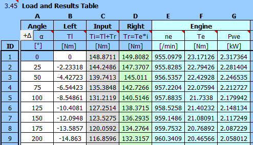
Since the ratio between the crank mechanism and the flywheel is 5:1, the flywheel turns 5 times for one revolution of the crank mechanism (1 working cycle). The division of the angle in the calculation of the crank mechanism was 5°, the division in the flywheel analysis table will thus be 5 * 5 = 25°
It is then possible to directly copy the T3 torque values into the second column (B).
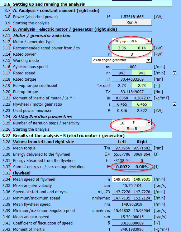
Under Motor/Generator selection [3.12], select the motor 1000 /min. The recommended rated power [3.13] is estimated based on the torque curve (column B).
Choose from the range of 3kW motors [3.14].
The flywheel: motor gear ratio (belt drive) is set automatically [3.22] so that the required flywheel revolutions are achieved.
Set the number of approximation steps to 10 and the sensitivity to 5 [3.25].
Press the "Start B" button. 10 steps will take place in sequence, during which the motor torque is repeatedly calculated from the flywheel revolutions. The value of the sum of the energies of the right and left sides [3.32] should decrease (reach the equilibrium state). You can press the button several times in a row to refine the results.
At the same time, the relevant moment of inertia is calculated [3.42].
In paragraph [2.0], enter the moment of inertia from the previous step, the density, the b/h ratio, and the inner diameter.
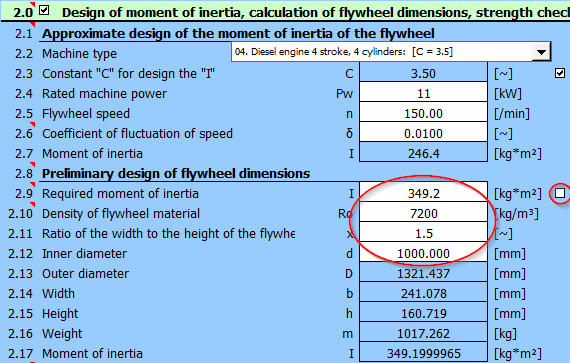
The flywheel ring parameters are on lines [2.13-2.17]
Information on setting of calculation parameters and setting of the language can be found in the document "Setting calculations, change the language".
General information on how to modify and extend calculation workbooks is mentioned in the document "Workbook (calculation) modifications".
Literature:
[1] Strojně technická příručka (Svatopluk Černoch)
[2] Shigley’s Mechanical Engineering Design
[3] Strojírenská
příručka (1992)
[4]
Machinery’s Handbook
(26th Edition)
Standards:
ČSN EN
60034-30-1 :20 14
EN 60034-30-1 :20 14
Rotating electrical machines — Part 30-1: Efficiency classes of line operated AC
motors (IE code)
Machines Olectriques tournantes — Partie 30-1: Classes de rendement pour les
moteurs a courant alternatif alimentés par le réseau (Code IE)
Drehende elektrische Maschinen — Teil 30-1: Wirkungrad-Klassifizierung von
netzgespeisten Drehstrommotoren (IE-Code)
Catalogues and company materials:
Siemens
ABB Automation Products
^