The program is intended for the design, calculation and validation of four basic types of friction brakes and clutches. It also allows the user to determine the kinetic energy and loading moments of the mechanisms.
The program performs following tasks:
1. Calculation of brake loads
2. Calculation of clutch starting load
3. Validation of a loaded clutch
4. Design and validation of:
- Disc brakes/clutches
- Cone brakes/clutches
- Drum brakes/clutches
- Band brakes/clutches
5. Calculation and temperature validation of the designed brake / clutch
The calculation uses data, procedures, algorithms and data from specialised literature, standards and company catalogues.
[1] Clutches and Brakes Design and
Selection; [2] Shigley's Mechanical Engineering Design; [3] Textbook of Machine
Design; [4] Brake Design and Safety; [5] Roloff / Matek - Maschinenelemente
VDI 2241-Blatt 1; VDI 2241-Blatt 2; SAE J866; SAE J661; Ortlinghaus, Goizper,
TAROX, FERODO
![]() User interface.
User interface.
![]()
Download.
![]()
Purchase, Price list.
Information on the syntax and control of the calculation can be found in the document "Control, structure and syntax of calculations".
Information on the purpose, use and control of the paragraph "Information on the project" can be found in the document "Information on the project".
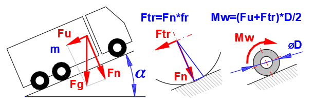
The friction brakes and clutches do not differ in physical nature. The difference is only in the waythe brake/clutch is loaded, their geometric design and control. The specific solution and the corresponding calculation also correspond to this. The given relationships are universal.
The solution of a brake/clutch calculation usually consists of two related tasks.
1. Calculation of the brake/clutch load based on the braking/running
mechanism - paragraph [1] in the Calculation.
2. Calculation of brake/clutch dimensions to meet the required load - paragraphs
[2],[3],[4],[5] and [8] in the Calculation.
The braked mechanism has a kinetic energy Ek at the beginning of the braking
cycle (It depends on the square of the speed.).
- Rotational motion
- Rectilinear motion
And at the same time, it is subject to forces and moments that
decrease/increase the brake load (they are constant during the braking cycle).
- Bearing frictional forces
- External influence (braking on an inclined plane)
- Aerodynamic drag (not constant) etc.
Braking time is an another variable.
The solution to these relationships is the torque that the brake must develop and the energy that must be absorbed by the brake.
For the clutch, the analogous procedure applies as it does for the brake (starting the mechanism -> reaching the desired Ek).
It is possible to separate the two tasks and to obtain, for example, the basis for the selection of the brake/clutch from the manufacturer's catalogue, or to design the brake/clutch on the basis of the load.
The following paragraphs contain formulas for load calculation, energy calculation, formulas used for friction brake and clutch dimensioning and temperature calculations.
Kinetic energy is calculated as the sum of the kinetic energy of straight-line motion and the energy of rotation of the mass.
Ek [J]= 0.5 * m * v2 + 0.5 * I * ω2
m ... mass of the braked mass [kg]
v .... velocity of the braked mass [m/s]
I .... moment of inertia of the braked mass [kg*m²]
ω ... speed of the braked mass with moment of inertia I [rad/s]
When braking or starting a mechanism,
there are usually additional forces or moments that must be included in the
calculation. These can be wheel rolling resistance, bearing rolling resistance,
forces due to mass (crane, lift, movement on an inclined plane), friction,
aerodynamic resistance, etc.
All these additional forces and moments must then be converted to brake/clutch
speed by the appropriate gear ratio.
For example, if the vehicle wheel speed is nw=100 [rpm] and the clutch speed is nc=2000 [rpm], the additional ML moment applied to the clutch is:
ML = Mw * nw / nc
ML ... the additional load / unload moment
Mw ... moment applied to the vehicle wheel
nw ... wheel speed
nc .... clutch speed
With multiple rotating and moving parts with different speeds, it is useful to add their kinetic energies and convert them to a reduced moment of inertia based on brake/clutch speed for further calculations.
Ired [kg*m²] = 2 * Ek / (n / 60 * 2 * p)2
Ek ... sum of kinetic energies [J)
n ..... brake/clutch speed [/min]
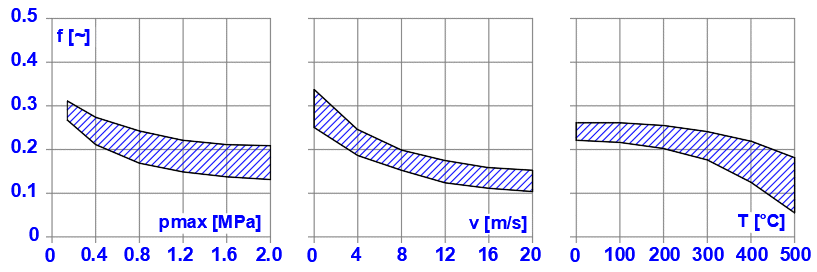
The coefficient of friction is the basic parameter that most influences the brake/clutch dimensions. It depends on the materials used and their combination. In the Calculation, it is possible to choose from the basic areas of friction materials. However, we strongly recommend that you follow the specific values of the manufacturer or supplier.
Example of how the coefficient of friction f [~] can vary depending on pmax [MPa], v [m/s] and T [°C] for dry friction for the material combination Powdered metal / steel.
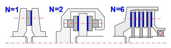
Disc brakes and disk clutches are some of the most common types of brakes and clutches. They have simple construction, large friction surface area, and good heat dissipation. It is possible to use designs with one or more friction surfaces, especially when the design with 2 friction surfaces is significantly used in the automotive industry (disc brakes, disc clutches).
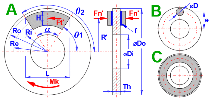
Since the principle of brakes and couplings is not different for the calculation, a common procedure is used with the dimensions defined by the figure below. Brakes are usually designed in such a way that the friction element is an annular sector pad or circle (A, B) and the clutch is an annular contact (C).
Two approaches are used for the solution.
A. Uniform wear (run-in brake/clutch): It is based on the assumption that the friction discs are rigid and the greatest wear occurs first on their outer circumference, where the work of frictional forces is the greatest. After some wear occurs, the pressure distribution changes, so that the wear of the friction surfaces is even.
B. Uniform pressure (new brake/clutch): It assumes that by using springs that evenly press the friction discs into contact, a uniform pressure is achieved over the entire friction surface.
Generally, approach A is used.
Maximum pressure
pmax [MPa] =(2 * Mk) / (a *
f * Re
* (Ro^2 - Ri^2)
/ 1000000 /
FillCoeff
Equivalent radius Re
Re [m] = (Ro + Ri) / 2
Friction force
Ft [N] = Mk / Re
Normal force
Fn [N] = Ft / f
Point of action of the normal force
R' [m] = (COS(q1) -
COS(q2)) / (q2 -
q1) * (2/3) * ((Ro^3 - Ri^3) / (Ro^2 - Ri^2))
Maximum pressure
pmax [MPa] = (3 * Mk) / (a * f * (Ro^3 - Ri^3)) / 1000000 / FillCoeff
Equivalent radius Re
Re [m] = 2 / 3 * (Ro^3 - Ri^3) / (Ro^2 - Ri^2)
Friction force
Ft [N] = Mk / Re
Normal force
Fn [N] = Ft / f
Point of action of the normal force
R' [m] =
(COS(q1) - COS(q2))
/ (q2 -
q1) * ((Ro
+ Ri)/2)
Mk .................... Load moment [Nm]
a
..................... Friction segment angle [rad]
f ....................... Friction coefficient [~]
Ro .................... Outer radius [m]
Ri ..................... Inner radius [m]
FillCoeff ............ Filling coefficient [~]
q1,q2
.............. Complementary angles [rad]
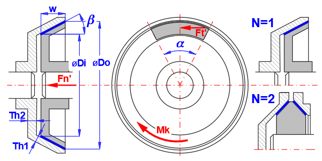
A conical surface is used as a friction surface. The advantage of this design is a lower actuation force Fn than a disc brake/clutch. Depending on the friction material, a cone angle b in the range of 10 -15° is usually used.
The solution is carried out similarly to the previous case, by determining the relations that are valid for uniform wear of the lining and for uniform distribution of pressure over the entire friction surface.
Maximum pressure
pmax [MPa] = (Mk / (p
* f *
Di) * (8
* SIN(b)) /
(Do^2 - Di^2))
/ 1000000 /
a
Equivalent diameter De
De [m]=(Do +
Di) / 2
Friction force
Ft [N] = Mk
/ (De / 2)
Normal force
Fn [N] = Ft * SIN(b) / f
Maximum pressure
pmax [MPa] = (Mk /(p
* f) *
(12 * SIN(b))
/ (Do^3 -
Di^3)) / 1000000
/ (a / (2 * p))
Equivalent diameter De
De [m] = 2/3
* (Do^3 -
Di^3) / (Do^2
- Di^2)
Friction force
Ft [N] = Mk
/ (De / 2)
Normal force
Fn [N] = Ft * SIN(b) / f
Mk ..... Load moment [Nm]
a
...... Friction segment angle [rad]
b
...... Cone angle [rad]
f ....... Friction coefficient [~]
Do .... Outer diameter [m]
Di ..... Inner diameter [m]
Drum brakes with internal shoes are mainly used in the automotive industry. Outer shoe brakes and symmetric shoe brakes are used mainly in industrial applications.
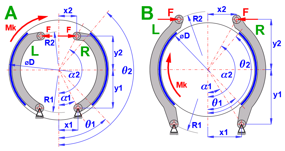
In principle, two types of shoes are used in drum brakes. Depending on the
sense of rotation (torque applied), they are referred to as Leading shoe R and
Trailing shoe L, as they are marked in the figure L, R.
For the same force F, the braking moments, pressures, forces and reactions are
different for the shoe (L) and (R).
The calculation is therefore principally carried out in the following steps
(leading (R) and trailing (L) shoe):
1. Calculation of the force F' for unit pmaxR'=1 for the leading shoe (R)
2. Calculation of the braking moment MR' for the leading shoe (R) for the force
F'
3. Calculation of pmaxL' for the left shoe(L) for the force F'
4. Of which the calculation of the braking moment for the left shoe (L) ML'
5. Calculation of the total braking torque Msum' = MR'+ML'
6. Calculation of the coefficient X, X = Mk / Msum'
7. Conversion of unit values of pressures, forces, moments and reactions by the
coefficient X
Frictional moment
Mt_R [Nm] = f * pmax * w * (D/2) /
SIN(qXa) * CoefA
CoefA =(D / 2 * (-(COS(qX2) - COS(qX1))) - a * ((0.5 * SIN(qX2)^2) -
(0.5*SIN(qX1)^2)))/1000
Normal moment
Mn_R [Nm] = pmax * w * (D/2) * a /
SIN(tqXa) * CoefB / 1000
CoefB =(qX2/2 - 1/4 * SIN(2 *
qX2)) - (qX1/2 - 1/4 * SIN(2 *
qX1))
Force F
F [N] = (Mn_R - Mt_R) / (c / 1000)
c [mm] = ABS(y1 - y2)
Braking moment M_R
M_R [Nm] = f * pmax * w * (D/2)^2 *
(COS(qX1) -
COS(qX2)) / SIN(qXa) / 1000
Pressure pmaxL
pmaxL [MPa] = (F * c / (Mn_R + Mt_R)) / 1000
Braking moment M_L
M_L [Nm] = f * pmaxL
* w * (D/2)^2 * (COS(qX1) - COS(qX2)) / SIN(qXa) / 1000
Braking moment Msum
Msum [Nm] = NR * M_R + NL * M_L
X coeficient
X = Mk / Msum
f ............. Friction coefficient [~]
pmax ...... Maximum pressure [MPa]
w ........... Shoe face width [mm]
D ........... Drum diameter [mm]
qX1 = q1 -
a1 [rad]
qX2 = q2 -
q1 + qX1 [rad]
qXa ... a) qX2 < PI()/2 ...
qXa = qX2, b)
qX2
> PI()/2 ...
qXa = PI()/2
NR, NL ... Number of braking elements (leading (R) and trailing (L) shoe )
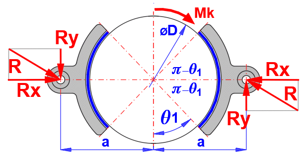
The distance "a" of the axis of the shoe pin from the axis of the drum, which ensures zero friction torque to the axis of the shoe pin. This ensures symmetrical wear of the lining.
a = 4 * (D/2) * SIN(q1') / (2 *
q1' + SIN(2 *
q1'))
q1' = pi()/2 -
q1
Maximum pressure
pmax [Mpa] = (Mk / (NL+NR)) / (2 * f * w * (D / 2)^2 *
SIN(q1')) / FillCoeff
Reaction in the pin of the shoe in
the x and y direction
Rx = pmax * w * (D/4) * (2 *
q1' +
SIN(2 *
q1'))
Ry = pmax * w * f * D/4 * (2 *
q1'
+ SIN(2 *
q1'))
where:
q1
............... brake lining start angle (see figure) [rad]
Mk ............... load moment [Nm]
NL, NR ......... number of braking elements [~]
f .................. coefficient of friction [~]
w ................. width of braking element [m]
D ................. outer diameter of drum [m]
q1'
............... half belt angle [rad]
FillCoeff ........ filling coefficient [~]
The friction surface consists of a belt that is wrapped around the brake drum. It is used in industrial applications, simple design. It is suitable for manual operation when high braking performance can be achieved with relatively low operating force.
ecoef = 2.7182818 (f *a)
Ft = Mk / ((Do / 2))
F2 = Mk / (ecoef - 1) * (Do / 2))
F1 = Ft + F2
Maximum pressure
pmax = (2 * F1 / (w * Do)) / N
Calculation of the force F
A: in the direction of rotation:
1 ... F = (Ft * a / L) * (1 / (ecoef - 1)) / N
2 ... F = (Ft * a / L) * (ecoef / (ecoef - 1)) / N
3 ... F = (Ft / L) * ((b * ecoef - a) / (ecoef - 1)) / N
4 ... F = (Ft / L) * ((b * ecoef + a) / (ecoef - 1)) / N
B: against the direction of rotation:
1 ... F = (Ft * a / L) * (ecoef / (ecoef - 1)) / N
2 ... F = (Ft * a / L) * (1 / (ecoef - 1)) / N
3 ... F = (Ft / L) * ((b - a * ecoef) / (ecoef - 1)) / N
4 ... F = (Ft / L) * ((b + a * ecoef) / (ecoef - 1)) / N
f ........... Friction coefficient [~]
Ft .......... Friction force [N]
Do ......... Drum outer diameter [m]
a
.......... Drum belt angle [rad]
N .......... Number of belts [~]
a,b,L ..... Lever dimensions [mm]
During both braking and starting, kinetic energy is converted into heat when the friction surfaces come into contact. The preceding paragraphs give the relationships for calculating the maximum torque and maximum pressure on the friction surfaces for the specified brake/clutch dimensions. Even if the maximum torque is not transmitted and the maximum allowable pressure is not exceeded, the brake/clutch may be destroyed by excessive heat.
This calculation obviously does not
cover all brake/clutch designs. (oil cooling, special geometries, special
materials, etc.). Therefore the following assumptions are used:
- The friction lining has a low thermal conductivity
l
compared to the thermal conductivity of the materials in contact with the
lining. (l
for friction lining ~ 0.1,
l
for steel ~ 54). Therefore, it is assumed that all the heat generated by
friction is absorbed by the metal part of the brake/clutch
- The thermal properties of the materials are constant (In the real case, of
course, they change, although not significantly)
- Braking time is an order of magnitude shorter than cooling time
- The weight of the clutch/brake (It is only an estimate. It is not a substitute
for a detailed analysis of the mass of the body receiving the heat generated by
friction)
Some manufacturers also specify a
maximum heat flux value q for friction segments.
q [W/mm²] = Eh / t / S''
Eh ..... The heat energy generated by the clutch/brake during the working cycle
[J].
t ........ Time of braking/clutch engagement [s]
S''' ...... Frictional area of disc/drum [mm²]
The temperature rise for the
brake/clutch can be approximately determined by the formula:
ΔT1 [°C] = Eh / (c * m)
Eh ... The thermal energy generated by the clutch/brake operation during the
duty cycle [J].
c ..... Specific heat capacity of the material [J/kg/K]
m .... Mass of the clutch/brake [kg]
As the formula does not take into account the time factor and cooling, it should
be taken as a guide.
Calculation of contact surface warming
ΔT2 [°C] = (5 / 18)^0.5 * (Eh * t^0.5) / (S'' * t *
(Ro * c *
l)^0.5)
Eh .......... Thermal energy generated by the clutch/brake during the duty cycle
[J]
Ro .......... Density [kg/m^3]
c ............ Specific heat capacity of the material [J/kg/K]
l
........... Thermal conductivity of the material [W/m/K]
t ............ Braking/clutch engagement time [s]
S'' .......... Frictional area of disc/drum [m^2]
Heat transfer time tb to reach the
outer surface of the drum
tb [s] = Th^2 / (5 * (l / (Ro * shc)))
Th .......... Drum/disc thickness [mm]
c ............. Heat capacity of the material [J/kg/K]
The previous equation ΔT1 [°C] = Eh / (c * m) can be used together with Newton's cooling law, which describes the heat transfer from the clutch/brake surface.
After appropriate simplification and the use of simplifying assumptions, we obtain this equation:
(T - TA) / (T1 -TA) = exp(- (a * S) / (m * c) * t)
T ..... The surface temperature of the body at time t [°C].
TA ... Temperature of the immediate surroundings of the surface of the body -
air temperature [°C]
T1 ... Initial temperature of the surface of the body [°C]
a
.... The heat transfer coefficient by flow and radiation [W*m^-2/K]
S ..... External surface area of the body [m²]
m .... Mass of the body (brake, clutch)
c ..... Specific heat capacity of the material [J/kg/K]
t ..... Cooling time [s]
For repeated use, the braking process can then be described as shown in the figure below:
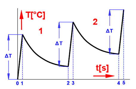
0-1 ... Braking of the mechanism -
frictional energy absorption, temperature increase
1-2 ... Transfer of energy to the environment (cooling - temperature drop)
2-3 ... Next braking cycle, temperature increase
3-4 ... Transfer of energy to the environment (cooling - temperature drop)
..................
The temperature development for a repeated cycle can then look like this.
When the temperature of the brake/clutch rises, the heat transfer coefficient a increases accordingly, so that at a certain temperature the energy input (braking process) and the energy output (cooling) are balanced.
The heat transfer coefficient a in the case of this calculation is influenced by 3 parameters and the following relation is used for its calculation:
a = aR + aC * fv
aR
.... Radiative heat transfer coefficient [W*m^-2/K]
aC
.... Heat transfer coefficient by flow [W*m^-2/K]
fv ...... Air flow coefficient [~]
The following graph can be used to
determine the coefficients
aR
and
aC:
dT = T - TA
T ..... The surface temperature of the body at time t [°C]
TA ... Temperature of the immediate surroundings of the body surface - air
temperature [°C]
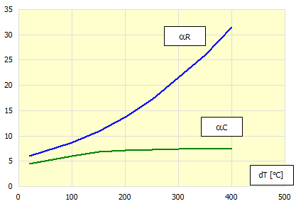
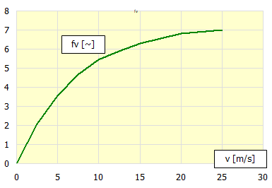
To determine the Air flow coefficient fv then:
This calculation simulates 100 steps of repeated braking/clutch engagement with a specified time interval. For each step, the corresponding heat transfer coefficient alpha is calculated, which is then used to calculate the temperatures in the next step. In most cases, this procedure is satisfactory and converges quickly to a steady state temperature.
In this calculation, you estimate the
total temperature increase. From this increase, the corresponding heat transfer
coefficient alpha is calculated, which is used for the overall warming
calculation. This procedure is dependent on the estimate of warming and may be
less accurate than the previous calculation. However, if the previous procedure
does not converge to a steady state end temperature, this calculation should be
used.
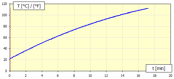
Example of a warming trend where it is appropriate to use the cumulative
calculation.
The solution of the brake/clutch calculation is usually divided into two tasks.
1. Calculation of the brake/clutch load based on the braked/actuated
mechanism [1].
2. Calculation of brake/clutch dimensions to meet the required load [2,3,4,5].
In paragraph 1.0, select the method of load calculation (brake/clutch) [1.3].
Enter or calculate the kinetic energy Ek and the moment ML (additional
calculations [6,7]) and enter the speed, time and operating parameters.
The result is the required moment and energy sufficient for the supplier's
brake/clutch specification or for the dimensional calculations in paragraphs
[2,3,4,5].
After selecting the brake/clutch type [2,3,4,5], enter the torque applied to
the brake/clutch.
Enter the friction surface parameters and friction element dimensions.
The result is the friction surface pressure, speed and applied forces.
By linking the calculation of the load [1] and the calculation of the
dimensions [2,3,4,5], it is then possible to solve other problems.
- Brake/clutch temperature during operation
- Optimization of dimensions
- Load optimization
In this paragraph you set the
calculation units and calculate the load torque and energy required for the
correct design of the brake/clutch dimensions.
Here you also set other parameters such as friction material properties,
brake/clutch material and load type.
Select the desired system of calculation units in the list box. After switching over the units, all values will be changed immediately.
To calculate brakes/clutches, it is
usually necessary to know "what we are braking" or "what we want to move". This
information leads to two basic parameters.
1. The torque that the brake/clutch must transmit
2. The energy the brake/clutch must absorb
Thus, there are three basic calculations of energy and torque.
A. Brake calculation
B. Starting clutch calculation
C. Running clutch check
The selected calculation is active, the remaining two are greyed out - inactive.
The geometric calculation of the specific brake/clutch type [2,3,4,5] then takes
the information about the load moment, energy, etc. from the selected energy and
moment calculation; as well as the brake/clutch warming calculation [8]
The task is to brake the moving mechanism to the required state (usually to a
stop n2=0).
In this case, we solve the problem where the kinetic energy Ek and the
additional moments ML must be converted into thermal energy in the friction
brake.
Used assumptions and simplifications:
- All braked masses are interconnected at constant transmission
- The load moment ML is constant during the braking process
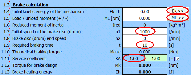
It is the kinetic energy of the moving masses you need to brake. To calculate them, you can use the paragraphs [6.0], where you can switch with the "Ek >>" button.
It is a load/unload moment (+ / -) converted to brake speed n1.
To solve common tasks, press the "ML >>" button.
Loading examples (+):
- Vehicle movement downhill
- Elevator, crane (mass applied force)
Unloading examples (-):
- Vehicle movement uphill
- Rolling resistance of the mechanism
It is a moment of inertia converted from all braked masses (rotational, linear motion - see Ek calculation) to the initial speed of the braked disc (drum) n1.
Enter the initial speed of the brake disc or drum.
Enter the end speed of the brake disc or drum. For a complete stop of the braking mechanism n2 = 0.
It is a required braking time from speed n1 to n2.
It is a theoretically calculated torque (assuming optimum conditions) that the brake must provide during the braking cycle.
Since the braking mechanism may exhibit non-uniformity (torque oscillation), it is advisable to use a coefficient (KA) that takes this unevenness into account and guarantee the required braking time. The design of the KA coefficient is based on practical knowledge and its size is governed by the setting of the conditions on line [1.41].
You can enter your own value by unchecking the check button.
It is the torque that the brake must capture. This torque value is used to calculate the brake dimensions [2,3,4,5].
It is the amount of energy that must be dissipated in the brake (brake warming).
The task is to run the mechanism to the desired state (usually from n2=0 to n1=required speed). In this case, we solve the problem when it is necessary to supply to the mechanism such energy Ek, which is necessary to achieve the required speed and revolutions while overcoming the additional moments ML.
Used assumptions and simplifications:
- The speed n1 (drive) is constant during the clutch operation
- A constant moment is transmitted => the acceleration of the mechanism is
constant
It is the kinetic energy to which the mechanism must be accelerated. You can use paragraphs [6] for the calculation, where you can switch with the "Ek >>" button.
Load / unload moment (+ / -) related to the clutch speed n1.
To calculate the usual tasks, press the "ML >>" button.
Loading examples (+):
- Starting the vehicle uphill
- Rolling resistance of the mechanism
- Elevator, crane (mass applied by force)
Unloading examples (-):
- Starting the vehicle downhill
Moment of inertia converted from all expanding masses (rotational, linear motion - see Ek calculation) to the initial speed of the clutch disc (drum) n1.
The power of the driving machine that is supplied to the clutch.
Enter the speed of the clutch on the drive side. The mechanism will be accelerated to this speed.
In most cases, you will be dealing with starting a stopped mechanism (n2=0).
If you need to solve a mechanism that is already in motion (n2>0) and accelerate it to speed n1, enter the initial speed n2.
It is the torque delivered by the driving machine.
Since both the driven mechanism and the driving machine may exhibit non-uniformity (torque oscillation), it is convenient to use the coefficient (KA). This coefficient takes this non-uniformity into account when calculating the torque that the coupling must transmit.
The design of the KA coefficient is based on practical knowledge and its size is governed by the setting of the conditions in line [1.40, 1.41 and 1.42].
To enter your own value, uncheck the check button.
It is the torque that the clutch must transmit. This torque value is used to design the dimensions of the coupling [2,3,4,5].
The generally reported efficiency of friction clutch is approximately 0.95.
This is the portion of torque that is supplied by the driving machine and is
fully utilized to achieve the desired final Ek of the mechanism.
The other part of the torque is dissipated in the clutch in the form of
friction.
The moment Mu is reduced/increased by the value of ML [1.16].
The required clutch operation time is calculated (value in the green field)
based on:
- The required end kinetic energy of the mechanism Ek [1.15]
- Load moment ML [1.16]
- Engine power Pw [1.18]
- Clutch efficiency h [1.24]
To enter your own clutch operation time, uncheck the check button. Then the value Ek '[1.27], to which the mechanism is accelerated, corresponds to the entered time.
It is the kinetic energy of the mechanism that is achieved by engaging the clutch in the time specified in the previous line.
It is the energy that is converted to heat in the clutch.
When solving the energy transfer
through a friction clutch, it is advisable to check the functionality under
operating conditions.
The clutch may be suitable for starting the mechanism (see previous calculation
- starting) but may not be suitable for steady state energy transfer when the
operating parameters are reached.
Example:
The clutch will ensure the mechanism starts at n1 at the specified power Pw.
The driving machine, with the clutch engaged, further increases the power Pw and
the speed n to the operating values.
The clutch must ensure torque transmission even under operating conditions.
The power of the driving machine that is supplied to the clutch.
Enter the operating speed of the clutch at which the corresponding power is taken.
It is the torque delivered by the driving machine.
Since both the driven mechanism and the driving machine may exhibit non-uniformity (torque oscillation), it is convenient to use the coefficient (KA). This coefficient takes this non-uniformity into account when calculating the torque that the coupling must transmit.
The design of the KA coefficient is based on practical knowledge and its size is governed by the setting of the conditions in line [1.40, 1.41 and 1.42].
To enter your own value, uncheck the check button.
It is the torque that the clutch must transmit. This torque value is used to design the dimensions of the coupling [2,3,4,5].
This paragraph gives designs of shaft diameters (steel) which correspond to the desired loading (Mk). These values are orientation values only; it is advisable to use a more exact calculation for the final design.
When designing a brake/clutch, the exact load moment curves are usually not known.
Therefore, the KA coefficient is used in the calculations to tell, based on experience and testing, how to increase the torque so that the designed brake/clutch can handle the appropriate load nonuniformity.
For the brake calculation, the coefficient KA is suggested based on the type
of braking mechanism.
To calculate the clutch, the coefficient KA is suggested, which includes both
the braked mechanism and the drive machine and the operating time.
Select the appropriate type of driving machine from the list.
Working machine
Rarely full load
Generators, chain conveyors, centrifugal, compressors, sand blasting
blowers, textile machines, conveyor systems, fans and centrifugal pumps.
Full load, shock-free
Elevators, bucket conveyors, rotary kilns, wire winders, crane travel and
trolley drives, winches, agitators, shears, machine tools, washing machines,
looms, brick extruders
Full load, moderate shocks
Excavators, drilling rigs, briquetting presses, mine ventilators, rubber
rolling mills, hoisting drives, pug mills, reciprocating pumps, tumblers,
joggers, combination mills
Full load, strong shocks
Reciprocating compressors, frame saws, wet-presses, paper mangles, roller
conveyors, drying rolls, roller mills, cement mills, centrifuges
The list contains a basic list of used friction materials. The coefficient of friction and the maximum allowable pressure and application are given in brackets.
Based on the selected material, the values [1.45-1.49] are pre-filled.
Select a material that absorbs the energy dissipated when braking or starting the mechanism.
The selection has no influence on the calculation of the brake/clutch parameters. The material values are used to calculate the warming (weight).
Examples:
1. The disc brake absorbs the braking energy and is made of steel.
2. The clutch housing absorbs the loss energy and is made of aluminum.
Disc brakes and disk clutches are some of the most common types of brakes and clutches. They have simple construction, large friction surface area, and good heat dissipation. It is possible to use designs with one or more friction surfaces, especially when the design with 2 friction surfaces is significantly used in the automotive industry (disc brakes, disc clutches).
Two basic parameters are required for
the calculation and design of the brake/clutch. Torque Mk and friction
coefficient f.
These parameters, together with the definition of the dimensions, lead to the
calculation of the maximum pressure on the friction surface, the calculation of
the actuating force and, knowing the energy and time parameters from [1], the
calculation of the heating.
In the green field is the moment Mk from paragraph [1]. If you only need to solve the geometry for the specified torque Mk, uncheck the button on the right and enter the Mk to be transmitted by the brake/clutch. This breaks the connection with paragraph [1] and thus the warming and speed are not calculated (the results are grayed out).
By unchecking the check button on the right
you can enter a custom value.
The recommended value is based on the selected friction material [1.44].
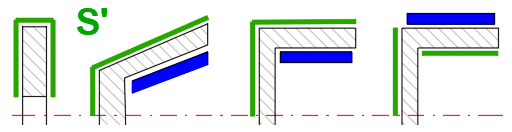
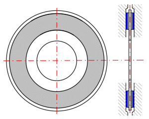
In this section you define the dimensions of the friction element. You can check the dimensions in the figure on the right.
There are three most common shapes to
choose from:
A. Annular sector pad - mostly used for brakes.
B. Circular (Button or Puck) - use for less stressed brakes (easy to
manufacture, simple design).
C. Annular contact - mostly used for clutches.
Depending on the choice of shape, the requirements for the respective input parameters are set.
Two approaches are used for the solution.
A. Uniform wear (run-in brake/clutch): It is based on the assumption that the friction discs are rigid and the greatest wear occurs first on their outer circumference, where the work of frictional forces is the greatest. After some wear occurs, the pressure distribution changes, so that the wear of the friction surfaces is even.
B. Uniform pressure (new brake/clutch): It assumes that by using springs that evenly press the friction discs into contact, a uniform pressure is achieved over the entire friction surface.
Generally, approach A is used.
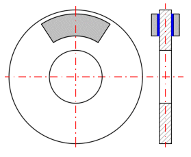
Enter the number of friction surfaces according to your design (see picture).
For the shape of the friction segment [2.5] A and C, enter: Outer radius of the friction segment Ro (see picture).
For shape B, enter: Distance of the centre of the circle "e" from the axis (see picture).
On the right, the optimum value of H (or D for a circular segment) is proposed to achieve the maximum friction torque from the relation Ri = Ro / 1.732.
You can enter your own value by unchecking the check button on the right.
For the friction segment shape [2.5] A, enter the segment angle (see picture).
Based on the area characteristic of the friction segment, the equivalent radius Re is calculated, which is used to calculate the forces.
It is the radius at which the normal force Fn' should act.
Brake (clutch) linings are often attached with rivets. This coefficient expresses the reduction of the friction surface of the lining by the respective mounting holes.
For glued linings cF = 1.0 and for riveted linings cF ~ 0.90 - 0.95.
It is the area over which the friction segment abuts the friction surface. It depends on the definition of the friction segment dimensions.
It is the area of the brake/clutch, which the friction segment is in contact with (indicated by a dashed line if visible on the outline).
This section gives the values for one friction surface.
Total moment Mk divided over the individual friction surfaces.
Most friction material manufacturers also state the maximum value of friction speed that the material can handle. The recommended value is based on the choice of material [1.43].
It is the maximum pressure at the most heavily loaded point of the lining. Lining manufacturers usually state its maximum value (see recommended value on the right). If the recommended maximum value is exceeded, try to modify the geometry or the type of lining.
Some manufacturers also provide a maximum recommended heat flux value q for friction segments.
The friction lining has a poor thermal conductivity lambda compared to the thermal conductivity of the materials in contact with the lining. (lambda of friction lining ~ 0.1, lambda for steel ~ 54). Therefore, it is assumed that all heat generated by friction is absorbed by the metal part of the brake/clutch.
This indicative calculation uses only the weight of the disc (cone, drum) m. Ssee the calculation below. The calculation is correct if the disc is the energy recipient (typically a disc brake).
For other design arrangements (typically a clutch), the frictional energy is absorbed, for example, by the clutch housing, and the result is obviously invalid.
It is assumed that the braking/clutch engagement process is short. Therefore, no cooling during this process is considered. The calculation of the friction surface warming is based on this assumption, where only the heat transfer to the disc (drum, housing, etc.) is considered based on the thermal conductivity of the material.
Problems like:
- How to change the dimensions to reach the allowed pmax
- How can the brake/clutch be loaded to achieve the allowed pmax
- What can be the maximum force Fn'
and others can be easily solved using the excel function "GoalSeek".
For the most common tasks the inputs to this function and its call are predefined.
After selecting the query and entering the desired value, the "Run" button will start the function execution.
You can return to the original value of the changed parameter by pressing the "Back" button. (The functionality is time-limited to prevent unwanted overwriting of values).
Example:
You want to calculate the friction segment angle for a disc brake that will
provide the required maximum pressure "pmax". It is clear that the friction
segment angle can only be within a certain range, but there is no limit to the
pmax requirement. So a requirement for a large change in pmax can lead to a
completely meaningless alpha segment angle.
Select the problem you want to solve from the list.
Enter the desired value to be reached by changing the input parameter and call the "Solution search" function using the button on the right.
The dimensional parameters are estimated on the basis of the previous data. After unchecking the check button on the right, you can enter your own dimensions (see figure).
The mass value is used to calculate ΔT1.
The area value is used for the cooling calculation in paragraph [8].
The value of surface S' is used as a default for the calculation of warming in paragraph [8] and is not used in this paragraph.
The area S' is calculated according to the figure.
A conical surface is used as a friction surface. The advantage of this design is a lower actuation force Fn than a disc brake/clutch. Depending on the friction material, a cone angle b in the range of 10 -15° is usually used.
Two basic parameters are required for
the calculation and design of the brake/clutch. Torque Mk and friction
coefficient f.
These parameters, together with the definition of the dimensions, lead to the
calculation of the maximum pressure on the friction surface, the calculation of
the actuating force and, knowing the energy and time parameters from [1], the
calculation of the heating.
In the green field is the moment Mk from paragraph [1]. If you only need to solve the geometry for the specified torque Mk, uncheck the button on the right and enter the Mk to be transmitted by the brake/clutch. This breaks the connection with paragraph [1] and thus the warming and speed are not calculated (the results are grayed out).
By unchecking the check button on the right
you can enter a custom value.
The recommended value is based on the selected friction material [1.44].
In this section you define the dimensions of the friction element. You can check the dimensions in the figure on the right.
There are two options to choose from:
A. Section of the conical surface - this construction is used rarely
B. Complete conical surface - used for brakes and clutches
Depending on the choice of shape, the requirements for the respective input parameters are set.
Two approaches are used for the solution.
A. Uniform wear (run-in brake/clutch): It is based on the assumption that the friction discs are rigid and the greatest wear occurs first on their outer circumference, where the work of frictional forces is the greatest. After some wear occurs, the pressure distribution changes, so that the wear of the friction surfaces is even.
B. Uniform pressure (new brake/clutch): It assumes that by using springs that evenly press the friction discs into contact, a uniform pressure is achieved over the entire friction surface.
Generally, approach A is used.
Enter the number of friction surfaces according to your design (see picture).
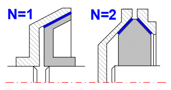
Enter the dimensions of the friction segment as shown.
You can specify the cone angle or the cone width. Use the switch on the right to set the option.
Based on the area characteristic of the friction segment, the equivalent diameter De is calculated, which is used to calculate the forces.
It is the area over which the friction segment abuts the friction surface. It depends on the definition of the friction segment dimensions.
It is the area of the brake/clutch, which the friction segment is in contact with (indicated by a dashed line if visible on the outline).
This section gives the values for one friction surface.
Total moment Mk divided over the individual friction surfaces.
Most friction material manufacturers also state the maximum value of friction speed that the material can handle. The recommended value is based on the choice of material [1.43].
It is the maximum pressure at the most heavily loaded point of the lining. Lining manufacturers usually state its maximum value (see recommended value on the right). If the recommended maximum value is exceeded, try to modify the geometry or the type of lining.
Some manufacturers also provide a maximum recommended heat flux value q for friction segments.
The friction lining has a poor thermal conductivity lambda compared to the thermal conductivity of the materials in contact with the lining. (lambda of friction lining ~ 0.1, lambda for steel ~ 54). Therefore, it is assumed that all heat generated by friction is absorbed by the metal part of the brake/clutch.
This indicative calculation uses only the weight of the disc (cone, drum) m. Ssee the calculation below. The calculation is correct if the disc is the energy recipient (typically a disc brake).
For other design arrangements (typically a clutch), the frictional energy is absorbed, for example, by the clutch housing, and the result is obviously invalid.
Note: The calculation includes one braking/running cycle. For a more detailed analysis use paragraph [8].
It is assumed that the braking/clutch engagement process is short. Therefore, no cooling during this process is considered. The calculation of the friction surface warming is based on this assumption, where only the heat transfer to the disc (drum, housing, etc.) is considered based on the thermal conductivity of the material.
Problems like:
- How to change the dimensions to reach the allowed pmax
- How can the brake/clutch be loaded to achieve the allowed pmax
- What can be the maximum force Fn'
and others can be easily solved using the excel function "GoalSeek".
For the most common tasks the inputs to this function and its call are predefined.
After selecting the query and entering the desired value, the "Run" button will start the function execution.
You can return to the original value of the changed parameter by pressing the "Back" button. (The functionality is time-limited to prevent unwanted overwriting of values).
Example:
You want to calculate the friction segment angle for a disc brake that will
provide the required maximum pressure "pmax". It is clear that the friction
segment angle can only be within a certain range, but there is no limit to the
pmax requirement. So a requirement for a large change in pmax can lead to a
completely meaningless alpha segment angle.
Select the problem you want to solve from the list.
Enter the desired value to be reached by changing the input parameter and call the "Solution search" function using the button on the right.
The dimensional parameters are estimated on the basis of the previous data. After unchecking the check button on the right, you can enter your own dimensions (see figure).
The mass value is used to calculate ΔT1.
The area value is used for the cooling calculation in paragraph [8].
The value of surface S' is used as a default for the calculation of warming in paragraph [8] and is not used in this paragraph.
The area S' is calculated according to the figure.
Drum brakes with internal shoes are mainly used in the automotive industry. Outer shoe brakes and symmetric shoe brakes are used mainly in industrial applications.
Two basic parameters are required for
the calculation and design of the brake/clutch. Torque Mk and friction
coefficient f.
These parameters, together with the definition of the dimensions, lead to the
calculation of the maximum pressure on the friction surface, the calculation of
the actuating force and, knowing the energy and time parameters from [1], the
calculation of the heating.
In the green field is the moment Mk from paragraph [1]. If you only need to solve the geometry for the specified torque Mk, uncheck the button on the right and enter the Mk to be transmitted by the brake/clutch. This breaks the connection with paragraph [1] and thus the warming and speed are not calculated (the results are greyed out).
By unchecking the check button on the right
you can enter a custom value.
The recommended value is based on the selected friction material [1.44].
In this section you define the dimensions of the friction element. You can check the dimensions in the figure on the right.
Select the desired type from the list.
Enter the number of trailing shoes
(L) and leading shoes (R).
If both the leading (R) and trailing (L) shoes are used, their numbers must be
identical. NL/NR = 1/1, 2/2, .....
It is also assumed that they are the same size and the same actuating force F.
If only the leading or trailing shoe is used, it is possible to choose any
number of shoes of the same dimensions.
Enter the position of the pin relative to the centre of the drum. You can switch the input method on the right. You can check the position in the figure on the right.
Specify the position of the force relative to the centre of the drum. You can switch the input method on the right. You can check the position in the figure on the right.
Enter the angle for the start and end of the braking segment. You can check the position in the figure on the right.
The distance of the shoe pin axis from the drum axis (Figure C), which ensures zero frictional moment to the shoe pin axis. This ensures symmetrical lining wear.
Brake (clutch) linings are often attached with rivets. This coefficient expresses the reduction of the friction surface of the lining by the respective mounting holes.
For glued linings cF = 1.0 and for riveted linings cF ~ 0.90 - 0.95.
It is the area over which the friction segment abuts the friction surface. It depends on the definition of the friction segment dimensions.
It is the area of the brake/clutch, which the friction segment is in contact with (indicated by a dashed line if visible on the outline).
The results are split for the leading (R) and trailing (L) braking shoes. When using R+L simultaneously, it is advisable to size the design for a more loaded (R) shoe.
Most friction material manufacturers also state the maximum value of friction speed that the material can handle. The recommended value is based on the choice of material [1.43].
It is the maximum pressure at the most heavily loaded point of the lining. Lining manufacturers usually state its maximum value (see recommended value on the right). If the recommended maximum value is exceeded, try to modify the geometry or the type of lining.
Some manufacturers also provide a maximum recommended heat flux value q for friction segments.
The friction lining has a poor thermal conductivity lambda compared to the thermal conductivity of the materials in contact with the lining. (lambda of friction lining ~ 0.1, lambda for steel ~ 54). Therefore, it is assumed that all heat generated by friction is absorbed by the metal part of the brake/clutch.
This indicative calculation uses only the weight of the disc (cone, drum) m. Ssee the calculation below. The calculation is correct if the disc is the energy recipient (typically a disc brake).
For other design arrangements (typically a clutch), the frictional energy is absorbed, for example, by the clutch housing, and the result is obviously invalid.
Note: The calculation includes one braking/running cycle. For a more detailed analysis use paragraph [8].
It is assumed that the braking/clutch engagement process is short. Therefore, no cooling during this process is considered. The calculation of the friction surface warming is based on this assumption, where only the heat transfer to the disc (drum, housing, etc.) is considered based on the thermal conductivity of the material.
Problems like:
- How to change the dimensions to reach the allowed pmax
- How can the brake/clutch be loaded to achieve the allowed pmax
- What can be the maximum force Fn'
and others can be easily solved using the excel function "GoalSeek".
For the most common tasks the inputs to this function and its call are predefined.
After selecting the query and entering the desired value, the "Run" button will start the function execution.
You can return to the original value of the changed parameter by pressing the "Back" button. (The functionality is time-limited to prevent unwanted overwriting of values).
Example:
You want to calculate the friction segment angle for a disc brake that will
provide the required maximum pressure "pmax". It is clear that the friction
segment angle can only be within a certain range, but there is no limit to the
pmax requirement. So a requirement for a large change in pmax can lead to a
completely meaningless alpha segment angle.
Select the problem you want to solve from the list.
Enter the desired value to be reached by changing the input parameter and call the "Solution search" function using the button on the right.
The dimensional parameters are estimated on the basis of the previous data. After unchecking the check button on the right, you can enter your own dimensions (see figure).
The mass value is used to calculate ΔT1.
The area value is used for the cooling calculation in paragraph [8].
The value of surface S' is used as a default for the calculation of warming in paragraph [8] and is not used in this paragraph.
The area S' is calculated according to the figure.
The friction surface consists of a belt that is wrapped around the brake drum. It is used in industrial applications, simple design. It is suitable for manual operation when high braking performance can be achieved with relatively low operating force.
Two basic parameters are required for
the calculation and design of the brake/clutch. Torque Mk and friction
coefficient f.
These parameters, together with the definition of the dimensions, lead to the
calculation of the maximum pressure on the friction surface, the calculation of
the actuating force and, knowing the energy and time parameters from [1], the
calculation of the heating.
In the green field is the moment Mk from paragraph [1]. If you only need to solve the geometry for the specified torque Mk, uncheck the button on the right and enter the Mk to be transmitted by the brake/clutch. This breaks the connection with paragraph [1] and thus the warming and speed are not calculated (the results are greyed out).
By unchecking the check button on the right
you can enter a custom value.
The recommended value is based on the selected friction material [1.44].
In this section you define the dimensions of the friction element. You can check the dimensions in the figure on the right.
It is the area over which the friction segment abuts the friction surface. It depends on the definition of the friction segment dimensions.
It is the area of the brake/clutch, which the friction segment is in contact with (indicated by a dashed line if visible on the outline).
The results determine the tensile force for one band F1 and F2 that is required to provide the required friction moment Mk.
Most friction material manufacturers also state the maximum value of friction speed that the material can handle. The recommended value is based on the choice of material [1.43].
It is the maximum pressure at the most heavily loaded point of the lining. Lining manufacturers usually state its maximum value (see recommended value on the right). If the recommended maximum value is exceeded, try to modify the geometry or the type of lining.
Some manufacturers also provide a maximum recommended heat flux value q for friction segments.
The friction lining has a poor thermal conductivity lambda compared to the thermal conductivity of the materials in contact with the lining. (lambda of friction lining ~ 0.1, lambda for steel ~ 54). Therefore, it is assumed that all heat generated by friction is absorbed by the metal part of the brake/clutch.
This indicative calculation uses only the weight of the disc (cone, drum) m. Ssee the calculation below. The calculation is correct if the disc is the energy recipient (typically a disc brake).
For other design arrangements (typically a clutch), the frictional energy is absorbed, for example, by the clutch housing, and the result is obviously invalid.
Note: The calculation includes one braking/running cycle. For a more detailed analysis use paragraph [8].
It is assumed that the braking/clutch engagement process is short. Therefore, no cooling during this process is considered. The calculation of the friction surface warming is based on this assumption, where only the heat transfer to the disc (drum, housing, etc.) is considered based on the thermal conductivity of the material.
Problems like:
- How to change the dimensions to reach the allowed pmax
- How can the brake/clutch be loaded to achieve the allowed pmax
- What can be the maximum force Fn'
and others can be easily solved using the excel function "GoalSeek".
For the most common tasks the inputs to this function and its call are predefined.
After selecting the query and entering the desired value, the "Run" button will start the function execution.
You can return to the original value of the changed parameter by pressing the "Back" button. (The functionality is time-limited to prevent unwanted overwriting of values).
Example:
You want to calculate the friction segment angle for a disc brake that will
provide the required maximum pressure "pmax". It is clear that the friction
segment angle can only be within a certain range, but there is no limit to the
pmax requirement. So a requirement for a large change in pmax can lead to a
completely meaningless alpha segment angle.
Select the problem you want to solve from the list.
Enter the desired value to be reached by changing the input parameter and call the "Solution search" function using the button on the right.
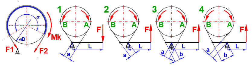
The most commonly used structural arrangement is shown in the figure.
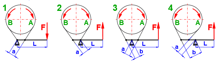
Select the type of structure, the sense of rotation of the drum and enter the desired dimensions. The result is the control force F.
Use: For one direction of rotation, manual operation.
Use: For one direction of rotation,
manual operation.
Advantage: A relatively small force F can be used to brake a large torque
mornent. For a = b . e^(f*alpha), F = 0. But braking would be jerky,
unsatisfactory.
Therefore, a > 2.5 * b is usually preferred.
Use: For both directions of rotation, for a = b, F is the same for both directions.
The dimensional parameters are estimated on the basis of the previous data. After unchecking the check button on the right, you can enter your own dimensions (see figure).
The mass value is used to calculate ΔT1.
The area value is used for the cooling calculation in paragraph [8].
The value of surface S' is used as a default for the calculation of warming in paragraph [8] and is not used in this paragraph.
The area S' is calculated according to the figure.
This chapter provides some additional calculations for determining brake/clutch loads and for warming calculation.
The primary role of the brake/clutch is to stop/accelerate a defined mass (To
remove/add kinetic energy Ek). In the vast majority of cases, these are the two
basic tasks.
1. Brake / accelerate rotating parts
2. Brake / accelerate directly moving components
3. Combination of the above tasks
The calculations in this paragraph allow defining 5 calculations for each task. Check / uncheck the check button in the header to add / remove the sum of Ek to/from the final result on line [6.6].
A common problem in Ek calculation is the solution of a rotating cylinder. Give the dimensions and speed as shown in the figure.
The mass of the rotating component and the radius of inertia are sometimes given. You can use this table to calculate Ek.
The moment of inertia is often given for rotating components. In this case, use this table to calculate Ek.
To calculate Ek, enter the mass and velocity of the moving parts. If you need to convert linear motion to rotational speed, enter the diameter of the wheel in the column marked D.
Depending on the setting of the calculation type [1.2], the Ek value will be transferred to [1.4] (brakes) or [1.15] (clutches) when the button is pressed.
In most cases, in addition to the
kinetic energy (see paragraph 6), the brake/clutch system is also loaded with an
additional torque, for example from:
- Frictional force of the bearings
- Frictional force of the mechanisms
- Movement on an inclined plane
- Aerodynamic drag
- etc.
The above calculations include the most commonly solved problems.
The value of the load moment ML can be transferred to paragraph [1] by pressing the ">> ML" button.
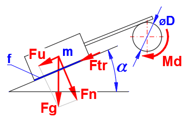
Calculation of the vehicle load/unload moment due to rolling resistance and movement on an inclined plane. Enter the required parameter values in the calculation.
Asphalt / Tire (truck)…(0.006-0.010)
Asphalt / Tire (passenger car)…(0.010-0.015)
Asphalt / Tire (motorcycle)…(0.010-0.015)
Asphalt / Tire (bike)…(0.002-0.005)
Pavement / Tire…(0.015-0.030)
Sand and gravel / Tire…(0.040-0.080)
Rail / Steel wheel…(0.001-0.002)
Depending on the setting of the calculation type [1.2], the Ek value will be transferred to [1.5] (brakes) or [1.16] (clutches) when the button is pressed.
The additional loading/lightening moment depends on the weight of the lifted equipment . Enter the required parameter values in the calculation.

Depending on the setting of the calculation type [1.2], the Ek value will be transferred to [1.5] (brakes) or [1.16] (clutches) when the button is pressed.
The additional loading/unloading moment depends on the mass, the coefficient of friction f and the angle of the inclined plane. Enter the required parameter values in the calculation.
=======Dynamic (v>0), Clean, Dry
========
Hardened steel - Hardened steel (0.1)
Hardened steel - Cast iron (0.13-0.27)
Hardened steel - Phosphore bronze (0.15)
Hardened steel - Wood (oak) (0.4-0.5)
Cast iron - Cast iron (0.15-0.2)
Cast iron - Phosphore bronze (0.15-0.2)
Cast iron - Wood (oak) (0.3-0.5)
Phosphore bronze - Phosphore bronze (0.2)
Leather - Cast iron (0.56)
Rubber - Cast iron (0.8)
Rubber - Concrete (0.7)
Rubber - Asphalt road (0.7)
Asbestos (textile) - Steel (0.3-0.35)
Nylon - Steel (0.3)
Polystyrene - Steel (0.5)
=======Dynamic (v>0), Lubricated ========
Hardened steel - Hardened steel (0.05-0.1)
Hardened steel - Cast iron (0.05-0.15)
Hardened steel - Phosphore bronze (0.09-0.15)
Hardened steel - Wood (oak) (0.08)
Cast iron - Cast iron (0.07-0.1)
Cast iron - Phosphore bronze (0.07-0.1)
Cast iron - Wood (oak) (0.2)
Phosphore bronze - Phosphore bronze (0.07-0.1)
Leather - Cast iron (0.15-0.35)
Rubber - Cast iron (0.5)
Rubber - Concrete (0.3-0.5)
Rubber - Asphalt road (0.2-0.3)
Asbestos (textile) - Steel (0.08-0.12)
During both braking and starting, kinetic energy is converted into heat when the friction surfaces come into contact. The preceding paragraphs give the relationships for calculating the maximum torque and maximum pressure on the friction surfaces for the specified brake/clutch dimensions. Even if the maximum torque is not transmitted and the maximum allowable pressure is not exceeded, the brake/clutch may be destroyed by excessive heat.
In this paragraph you can:
- Solve brake/clutch warming during single braking/clutch engagement.
- Simulate repeated brake/clutch application.
After the selection of an option from the list [8.2], the surface size and
weight values from the corresponding paragraph of the brake/clutch type
[2,3,4,5] are filled in.
However, for a reasonable calculation (estimation) of the thermal
characteristic, it is necessary to determine the surface area and mass as
accurately as possible with respect to the brake/clutch design used.
As an example, consider the difference between a disc brake and a disc clutch.
Disc brake:
Consists of a metal disc that is braked by friction pads. All the heat is stored
in the metal disc, which transfers the heat to the surrounding air. The values
of area and mass from paragraph [2] can be used to calculate the heat.
Disc coupling:
It is created by a thin disc with a friction lining that engages the metal
structure of the coupling. All the heat is thus stored in the coupling body. The
area and mass parameters are completely different from those proposed in
paragraph [2] and custom values must be entered.
To enter your own values, uncheck the check button on the right.
The value is preset based on the material selection [1.54].
The energy values are transferred according to the choice of the type of calculation in paragraph [1]. You can enter your own values by unchecking the check button on the right.
Values from [8.4, 8.5, 8.7] are used to calculate the temperature rise.
One cycle of braking/clutch engagement will result in an approximate temperature rise of ΔT. The value is approximate, for a more detailed description please refer to the theoretical part of the help.
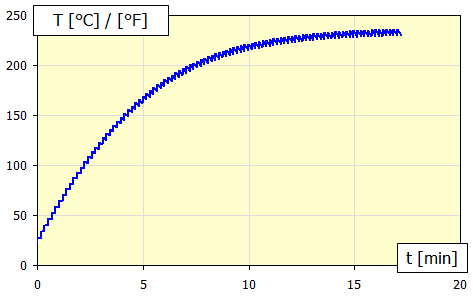
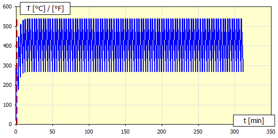
In this calculation, 100 steps of repeated braking/clutch engagement are simulated with a specified time interval [8.13]. For each step, the corresponding heat transfer coefficient alpha is calculated, which is then used to calculate the temperatures of the next step. In most cases, this procedure is satisfactory and converges quickly to a steady state temperature.
The temperature progression is shown in Figure B [8.25]. The x-coordinate is in minutes.
In the case of large brake/clutch thermal inertia (large mass), 100 iteration steps may be insufficient. This case can be recognized from graph B, where the curve does not converge to the steady state temperature Max/Min. In this case, use the cumulative calculation [8.17].
Enter the ambient air temperature.
The air velocity around the brake/clutch body significantly influences the heat transfer.
Therefore, try to estimate this value as accurately as possible.
The value is preset based on the calculation from [1]. You can enter your own value by unchecking the check button on the right.
Enter the time interval between repeated brake/clutch applications.
In Graph B you can usually see a gradual convergence to a steady state Min/ Max value.
The Min/ Max value is taken from the last step (#100) of the sequential iteration.
This calculation estimates the total temperature increase. From this increase, the corresponding heat transfer coefficient alpha is calculated and used for the overall warming calculation.
By unchecking the check button on the right, you can enter your estimate of the temperature rise. However, in most cases this is unnecessary and the recommended value in the green box is accurate enough.
Maximum brake/clutch temperature for an unlimited number of brake/clutch cycles.
You can enter the cycle number directly or set it with the slider on the right. The temperature progression of the selected cycle is shown in the graph.
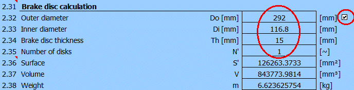
Design of a disc brake on the front axle of a passenger car + temperature analysis.
Car weight: m = 1600 kg
Initial speed v1 = 180 km/h (50 m/s)
End speed v2 = 0
Road gradient
a
= -5° (8.75%)
Average deceleration a = -7 m/s^2
Wheel diameter = 620 mm
Distribution of braking force 70% front 30% rear axle.
Repeated braking 180->0 km-h with a period of 180s
Braking time:
t = v1 / a; t = 50 / 7 => t = 7.14 s
v1-Initial velocity; a-Acceleration / Deceleration; t-time
Calculation assumptions:
- Aerodynamic drag is not included
- No wheel slip
- Linear progression
In paragraph [1] select the calculation units [1.1] and the brake calculation [1.2]
First, it is necessary to solve the brake load.
To calculate the kinetic energy Ek, use paragraph [6], pressing the button "Ek >>".
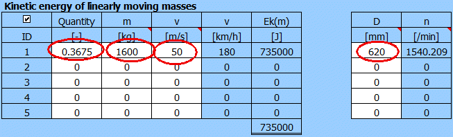
Ek calculation for one braking disc.
Front axle 70% load, one wheel => 0.7 / 2 = 0.35.
For passenger cars use a coefficient of 1.05 (which includes rotating braked
masses such as wheels, shafts, gears, etc...).
First column 0.35 x 1.05 = 0.3675.
Resulting Ek=735000 [J] and for a wheel diameter of 620mm => speed 1540 [/min].
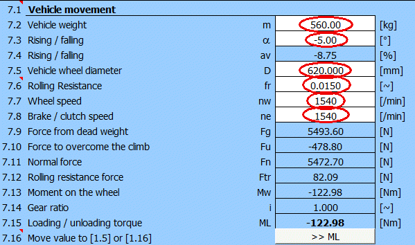
To calculate the additional ML load moment, use paragraph [7], press the "ML >>" button.
We will distribute the total mass of the vehicle on one wheel of the front
axle according to the previous consideration m=1600*0.35=560 [kg].
After entering the remaining data, we obtain the additional load moment 123 [Nm]
and we will transfer it to paragraph [1].
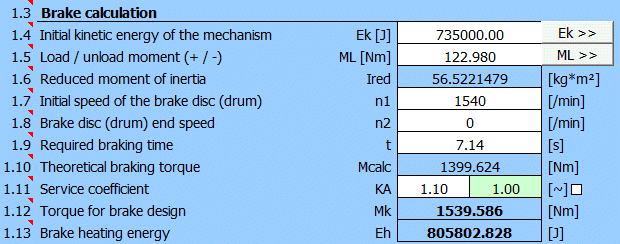
After filling in all the data and selecting KA=1.1, we have defined the parameters for calculating the dimensions of the disc brake (t, Mk, Eh).
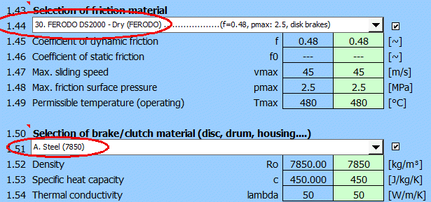
It is advisable to define (select) the brake lining material and brake disc material in paragraph [1] beforehand.
After switching to the paragraph for calculating the disc brake/clutch [2], set the initial parameters [2.1-2.7].
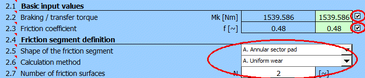
Select friction segment angle alpha [2.11] = 80°.
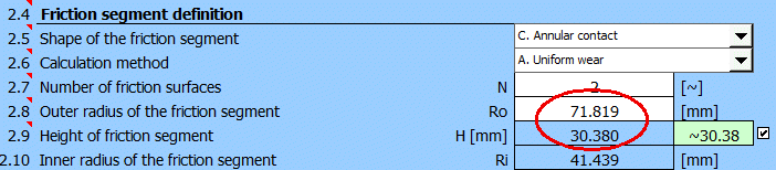
It is likely that the value of the maximum pressure pmax [2.24] will either exceed the permissible value from [1.48] or be too low and the brake potential will not be used.
Therefore, select the "Goal Seek"
(03.) for pmax on [2.29], enter the desired value of 2.5 [MPa] (see selected
material) and press the "Run" button.
The minimum outer radius of the friction segment to achieve the specified
pressure pmax=2.5 [MPa] will be searched.
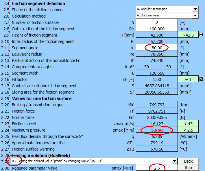
The Goel Seek will provide these results:
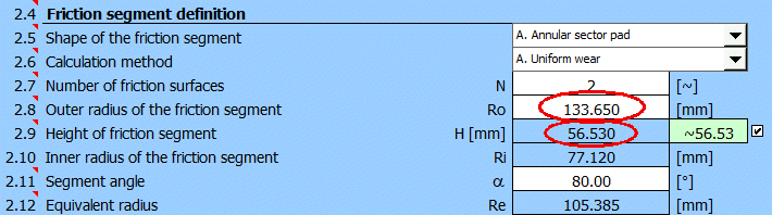
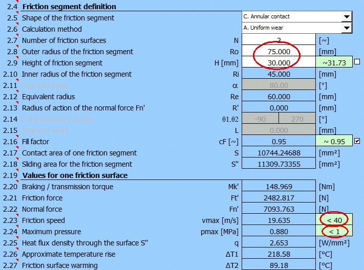
After a suitable choice of Ro and H values, the design of the disc brake will look as follows.
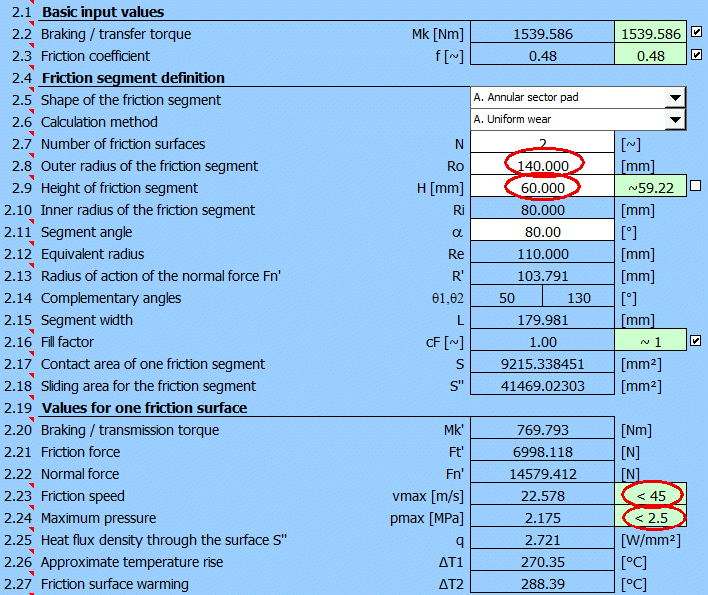
The design meets the basic requirements for friction speed and lining pressure while meeting the braking torque requirement of Mk.
A thermal analysis should be an
integral part of the brake design. The design of the brake disc dimensions is
included in paragraph [2]. These are necessary for the analysis.
For this example, use the preset (estimated) values.
After moving to paragraph [8], set the parameter values as follows:
- [8.3] The disk parameters from the selected disk brake calculation [2] are
used
- [8.7] The braking energy from paragraph [1] is used
Enter the air temperature, the air velocity (estimated to be half the vehicle
speed at the start of braking) and the desired time interval between braking.
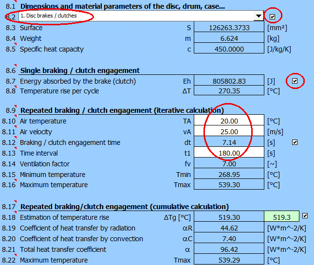
The result is a graph of the temperature rise and fall between each braking cycle.
Design of a disc clutch of a passenger car.
Car weight: m = 1600 kg
Engine power diagram
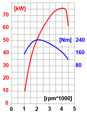
Estimated from the power chart:
- Selected speed for starting = 2500 [/min]
- Motor power for 2500 [/min] = 60kW
Initial speed v1 = 0
Final speed v2 = 25 km/h (7 m/s) for clutch speed 2500 rpm in 1st gear
Road gradient
a
= +5° (8.75%)
Wheel diameter = 620 mm
Calculation assumptions and
simplifications:
- Aerodynamic drag is not included
- There is no wheel slip
- Power and drive speed are assumed to be constant during clutch engagement
In paragraph [1] select the calculation units [1.1] and the coupling calculation [1.2].
First of all it is necessary to solve the load of the coupling.
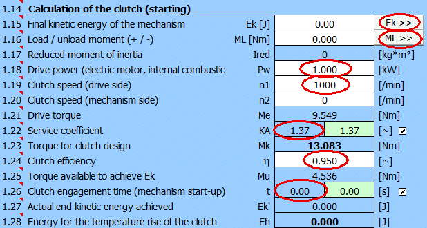
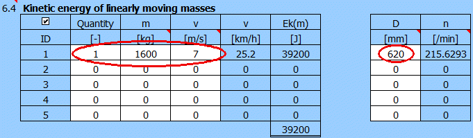
To calculate the final kinetic energy Ek, use paragraph [6], press the button "Ek >>".
Calculation of the final Ek. Resulting Ek=39200 [J] and for wheel diameter 620mm => speed 215 [/min].
To calculate the additional load moment ML, use paragraph [7], press the "ML >>" button.
Fill in weight, road grade, wheel diameter, wheel speed and clutch speed.
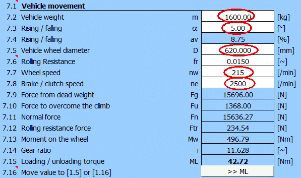
After entering the data, you get an additional load torque of 42.7 [Nm]. Transfer the value to paragraph [1].
After adding all the data and selecting KA=1.3, we have defined parameters for calculating the dimensions of the disc coupling (t, Mk, Eh).
Preliminarily, it is advisable to define (select) the material of the clutch lining and the material of the clutch housing in paragraph [1].
After switching to the paragraph for calculating the disc brake/clutch [2], set the initial parameters [2.1-2.7].
It is likely that the value of the maximum pressure pmax [2.24] will either exceed the permissible value from [1.48] or be too low and thus the coupling potential will not be used.
Select the "Goal seek" (03.) for pmax
on [2.29], enter a value of 1.0 [MPa] (see selected material) and press the
"Run" button.
The minimum outer radius of the friction segment to achieve the specified
pressure pmax=1.0 [MPa] will be searched.
The solution search will provide these results:
After a suitable choice of Ro and H values, the design of the coupling will look as follows:
The design meets the basic requirements for friction speed and lining pressure while meeting the braking torque requirement of Mk.
Calculation of the table of control force F and braking torque Mk for a defined brake.
Brake dimensions according to the picture [mm].
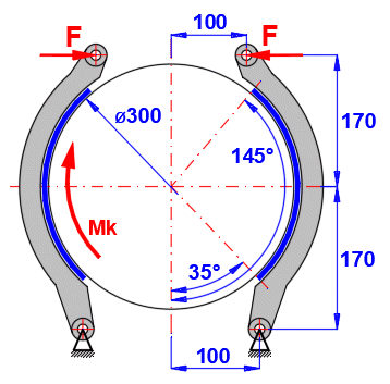
Brake lining friction coefficient
................ f = 0.4 [~]
Brake lining width ................................ w = 100 [mm]
Glued lining => .................................. cF = 1.0 [~]
Maximum brake lining pressure ........ pmax = 0.5 [MPa]
Enter the brake dimensions as specified (uncheck the buttons on the right to enter).
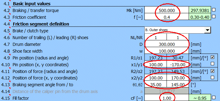
Gradually change the torque Mk [Nm] in the range 300-1100.
Results table:
| ID | Mk [Nm] | F [N] | pmaxR [MPa] |
| 1 | 500 | 1932 | 0.24 |
| 2 | 600 | 2319 | 0.29 |
| 3 | 700 | 2705 | 0.34 |
| 4 | 800 | 3092 | 0.39 |
| 5 | 900 | 3478 | 0.43 |
| 6 | 1000 | 3865 | 0.48 |
| 7 | 1100 | 4251 | 0.53 |
Using the "Goal seek" function on
[4.24-4.26] you can also find the maximum torque Mk and the maximum control
force F for the maximum permissible pressure pmax=0.5 [MPa].
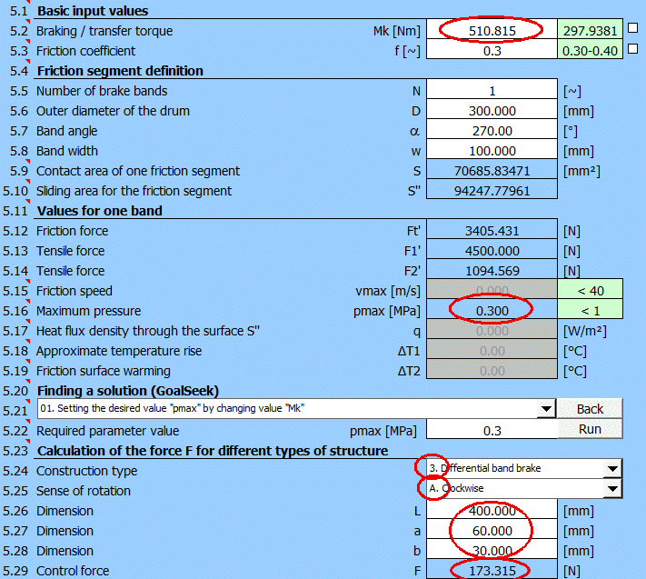
A band brake with the specified dimensions, find the maximum torque Mk and the actuating force F.
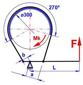
Brake dimensions as shown in the figure below: D=300mm, L=400mm, a=60mm, b=30mm
Brake lining friction coefficient
................ f = 0.3 [~]
Brake lining width ................................ w = 100 [mm]
Maximum brake lining pressure ........ pmax = 0.3 [MPa]
Enter the brake dimensions as specified (uncheck the buttons on the right to enter).
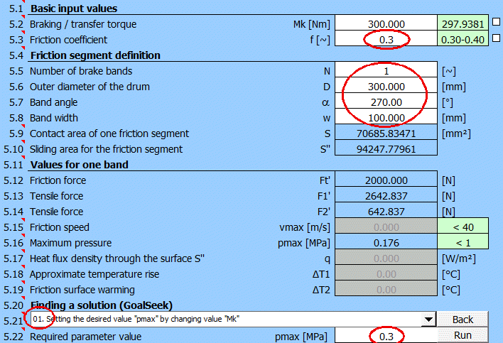
Select [5.21] "Goal seek" (01.) for pmax, enter the desired value 0.3 [MPa]
and press the "Run" button.
The moment Mk will be found to reach the specified pressure pmax = 0.3 [MPa].
After you select the type of control mechanism and enter dimensions, you will get the resulting solution: maximum torque Mk and control force F.
Information on setting of calculation parameters and setting of the language can be found in the document "Setting calculations, change the language".
General information on how to modify and extend calculation workbooks is mentioned in the document "Workbook (calculation) modifications".
Litrature:
[1] Clutches and Brakes Design and Selection Second Edition (William C. Orthwein)
[2] Shigley’s Mechanical Engineering Design (Richard G. Budynas, J. Keith Nisbett)
[3] Textbook of Machine Design (R.S. KHURMI, J.K. GUPTA)
[4] Brake Design and Safety Third Edition (Rudolf Limpert)
[5] Roloff / Matek - Maschinenelemente, Normung, Berechnung, Gestaltung
Standards:
VDI 2241-Blatt 1
Schaitbare fremdbetätigte Reibkupplungen und -bremsen.
Begriffe, Bauarten, Kennwerte, Berechnungen
Friction clutches and brakes Vocabulary, types, characteristic data,
calculations
VDI 2241-Blatt 2
Schaitbare fremdbetätigte Reibkupplungen und -bremsen,
Systembezogene Eigenschatten, Auswahlkriterien, Berechnungsbeispiele
Friction clutches and brakes Typ related properties, criteria for selection,
examples of calculations
SAE J866
Friction Coefficient Identification and Environmental Marking System for Brake
Linings
SAE J661
(R) BRAKE LINING QUALITY TEST PROCEDURE
Company cataloques: Ortlinghaus, Goizper, TAROX, FERODO...
^