The calculation is designed for a geometrical design and strength check of a prestressed bolt connection, loaded by static or cyclic loading resp., acting both in the axis of the bolt and in the plane of the connected parts. The application solves the following tasks:
Automatic design of a connection bolt of standard design.
Calculation and check of connections fitted with special shanks.
Design and calculation of necessary mounting prestressing of the connection and fastening torque.
Calculation of force conditions of a loaded connection.
Static and dynamic strength check.
The application includes a table of commonly used materials of bolts according to ISO, EN, SAE and ASTM, and a selection of materials of the connected parts according to AISI/SAE/ASTM, ISO, EN and DIN.
Support of 2D CAD systems.
The calculations use data, procedures, algorithms and data from specialized literature and standards ANSI, ISO,
EN, DIN.
List of standards: ANSI B1.1, ANSI 273, ANSI B18.2.1, ANSI B18.2.2, ANSI B18.3,
ANSI B18.6.2, ANSI B18.6.3, ANSI B18.22.1, ASTM A193, ASTM A307, ASTM A320, ASTM
A325, ASTM A354, ASTM A449, ASTM A453, ASTM A490, ASTM A574, ASTM F568M, ASTM
F593, ASTM F2281, SAE J429f, ISO 273, ISO 1207, ISO 4016, ISO 4032, ISO 4035,
ISO 4762, ISO 8738, ISO 8839, EN ISO 898, EN ISO 3506, EN 10269, EN 28839, VDI
2230
User interface.
Download.
Purchase, Price list.
Information on the syntax and control of the calculation can be found in the document "Control, structure and syntax of calculations".
Information on the purpose, use and control of the paragraph "Information on the project" can be found in the document "Information on the project".
Prestressed bolt connections form the majority of bolt and threaded connections used in practice. These connections are loaded with great internal axis force (mounting prestressing) during assembly. This prestressing provides the necessary force bond of contact surfaces of the connected materials.
In principle, the designed structural junction should behave as a compact formation. A correctly prestressed connection forms during operation of a cohesive unit with guaranteed force closing in the contact surfaces and unchanged mutual position of the connected parts. The mounting prestressing of a bolt connection thus includes two basic functions. In case of connections loaded in the plane of the connected parts, the prestressing meets the requirement of shear loading capacity with utilization of friction forces; in case of connections loaded in the axis of the bolt, it meets the requirement of compactness or tightness of the connection resp.
From the above-mentioned, the individual steps which are necessary for successful design of a prestressed bolt connection result:
It is advisable to use the following procedure during design and check:
For a connection with dynamic loading, select a design, desired service life, reliability and safety of the connection. [2.22 - 2.26]
In this paragraph it is first necessary to enter basic input parameters, characterizing the manner, mode and amount of loading and the type of connection.
In the selective list, select the desired system of calculation units. All values will be recalculated immediately after switching to other units.
In view of the construction, there are two basic methods of bolt connection design:
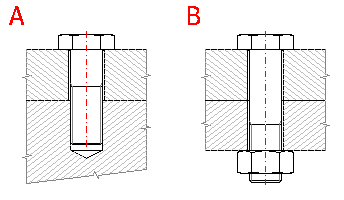
In the selective list, select the connection design.
Depending on the type of loading, a prestressed bolt connection must meet different requirements; this results in a different method of calculation of the mounting prestressing. There are three different ways of loading for purposes of calculations of bolt connections:
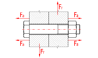
Select the desired type of loading in the selective list. After selection, the calculation will be modified into the configuration which corresponds with the selected type of loading - the parameters, which have no meaning for the selected type, will be hidden.
This list allows users to define the type (course) of loading which acts on the connection. The bolt connection can be designed for the following types of loading:
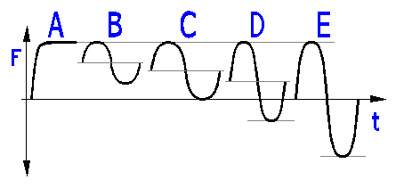
With connections exposed to cyclic loading (loading B to E) it is also necessary to carry out, in addition to common strength checks, checks of the connection bolt in view of fatigue strength.
Select the desired course of loading in the selective list. After selection, the calculation will be modified into the configuration which corresponds with the selected type of loading - the parameters, which have no meaning for the selected type, will be hidden.
In this row, enter operational forces acting on the bolt connection. In the row [1.7] enter the amount of static axial (axis) force or the upper value of amplitude of the force with cyclic loading. In the row [1.8] enter the lower value of amplitude of the force with cyclic loading. The row [1.9] can be used to enter the radial force, but always enter the maximum amount of this force.
This paragraph is designed for setting various operational and mounting parameters which are necessary for the design and calculation of a prestressed bolt connection.
A correctly prestressed bolt connection forms during operation a cohesive unit with guaranteed force bond on the contact surfaces and unchanged mutual position of the connected parts. This requirement of compactness, which is important particularly with connections exposed to variable loading, is extended in some cases by the requirement for connection tightness. The pressure on the contact surfaces caused by the prestressing must guarantee a hermetic bond of the connection during operation.
The requirement of compactness or tightness of the connection is applied with the design of the connection through this coefficient, which gives the ratio between the residual prestressing of the clamped parts of the connection and the maximum operational force. The option of this coefficient thus affects the amount of mounting prestressing of the designed connection. The coefficient is usually selected in the limits according to the following recommendations:
Requirement of compactness of the connection
| Connections loaded with a permanent force | 0.2 ... 1.5 |
| Connections loaded with a variable force | 0.5 ... 2 |
Requirement of tightness of the connection (higher values used with a variable force or with sealing of a dangerous medium)
| Soft sealing | 1 ... 2 |
| Metal profiled sealing | 1.5 ... 3 |
| Metal gasket | 2.5 ... 4 |
With a properly designed connection loaded in the plane of the connected parts, the entire radial force must be transferred using friction between the connected parts, which arises from the mounting prestressing. This safety coefficient gives the ratio between the actual residual prestressing in the connection and the minimum (calculated theoretically) clamping force necessary for entire transfer of the radial force. The requirement of the shear loading capacity of the connection should meet a safety level higher than 1, however, in fact with regards to technological properties of the operation and possible inaccuracy of theoretical determination of coefficients of friction between the connected surfaces, it is advisable to specify the safety against side shifts in a range from 1.5 to 3. The upper values are selected with connections exposed to a variable loading. With combined loading (see [1.4]) or loading with shocks, it is possible to use a higher safety level.
Adequately large residual prestressing of the clamped parts ensures the necessary force bond of the contact surfaces during operation.
The minimum permissible ratio of the yield point of the selected material of the bolt and the maximum reduced stress in the bolt core. The lower limit of safety at the yield point with connection bolts is usually selected with regards to the type of loading, importance of the connection, quality of production, operational conditions and accuracy of calculation, in a range from 1.5 to 3. The lower values are selected for connections exposed to a static loading, the upper values are selected for connections exposed to a variable loading. With important connections, connections exposed to shocks, connections working in a corrosive environment or at high operational temperatures, there are usually selected even higher values of safety (3 ... 6). General procedures of setting the safety coefficient can be found in the document "Coefficients of safety".
The size of the coefficient of friction in threads depends on the material, roughness, surface treatment and thread angle. The coefficient of friction is lower with flat threads. Coefficient of friction for a sharp thread:

where:
m'- coefficient of friction with flat threads
a - thread angle
Orientation values of the coefficient of friction for a sharp thread (thread angle 60°) are given in the table.
Non-lubricated thread (without any special lubrication, however, not degreased)
| Outer steel thread |
Inner thread |
|||
| Steel, untreated | Steel, galvanized | Grey cast iron | Al alloys | |
| Untreated | 0.12 ... 0.18 | 0.14 ... 0.20 | 0.12 ... 0.18 | 0.12 ... 0.23 |
| Phosphatised | 0.12 ... 0.18 | 0.14 ... 0.20 | 0.12 ... 0.18 | 0.12 ... 0.23 |
| Galvanized | 0.14 ... 0.23 | 0.14 ... 0.25 | 0.12 ... 0.19 | 0.14 ... 0.23 |
| Cadmium-coated | 0.09 ... 0.14 | 0.10 ... 0.16 | 0.09 ... 0.14 | 0.09 ... 0.15 |
| Degreased | 0.19 ... 0.25 | 0.19 ... 0.25 | 0.19 ... 0.25 | 0.19 ... 0.25 |
Lubricated thread
| Outer steel thread |
Inner thread |
|||
| Steel, untreated | Steel, galvanized | Grey cast iron | Al alloys | |
| Untreated | 0.10 ... 0.17 | 0.12 ... 0.18 | 0.10 ... 0.17 | 0.11 ... 0.20 |
| Phosphatised | 0.10 ... 0.17 | 0.12 ... 0.18 | 0.10 ... 0.17 | 0.11 ... 0.20 |
| Galvanized | 0.12 ... 0.20 | 0.12 ... 0.20 | 0.11 ... 0.18 | 0.12 ... 0.20 |
| Cadmium-coated | 0.08 ... 0.13 | 0.09 ... 0.15 | 0.08 ... 0.13 | 0.08 ... 0.14 |
The size of the coefficient of friction under the head (nut) of the bolt depends on the material of the nut and the clamped parts, roughness, surface treatment and lubrication. Orientation values of the coefficient of friction for a steel head of the bolt (nut) are given in the table.
| Head of the bolt (nut) |
Material of the clamped parts |
|||
| Steel | Galvanized steel | Grey cast iron | Al alloy | |
| Untreated, dry | 0.10 ... 0.18 | 0.10 ... 0.18 | 0.12 ... 0.20 | - |
| Phosphatised, dry | 0.10 ... 0.18 | 0.10 ... 0.18 | 0.12 ... 0.20 | - |
| Galvanized, dry | 0.10 ... 0.20 | 0.16 ... 0.22 | 0.10 ... 0.20 | - |
| Untreated, lubricated | 0.08 ... 0.15 | 0.08 ... 0.15 | 0.08 ... 0.16 | 0.08 ... 0.20 |
| Phosphatised, lubricated | 0.08 ... 0.15 | 0.08 ... 0.15 | 0.08 ... 0.16 | 0.08 ... 0.20 |
| Galvanized, lubricated | 0.09 ... 0.18 | 0.09 ... 0.18 | 0.10 ... 0.18 | - |
The size of the coefficient of friction between the connected surfaces depends on the material of the connected parts, roughness, surface treatment and degreasing of the connected surfaces. Orientation values of the coefficient of friction are given in the table.
| Surface treatment |
Material of the clamped parts |
|||
| Steel on steel | Steel on cast iron | Cast iron on cast iron | Al alloys | |
| Machined degreased surfaces | 0.12 ... 0.18 | 0.15 ... 0.25 | 0.18 ... 0.25 | 0.08 ... 0.15 |
| Areas without surface treatment | 0.15 ... 0.25 | 0.18 ... 0.30 | 0.20 ... 0.30 | 0.12 ... 0.20 |
| Scorched surfaces | 0.35 ... 0.55 | - | ||
| Sand blasted surfaces | 0.45 ... 0.55 | - | ||
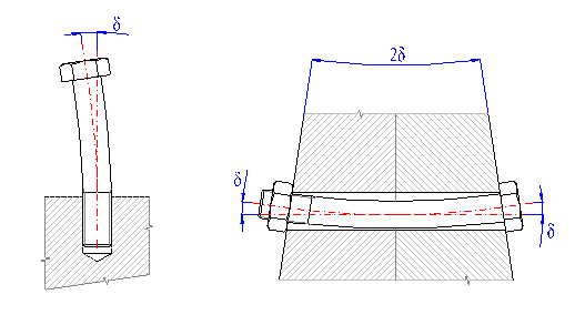
An additional bending stress appears in the bolt core in case of uneven seating of the head of the bolt or nut on the seating surfaces. Bending stress appears usually due to inaccuracy of production (seating surfaces below the head and nut are not parallel and perpendicular to the axis of the bolt) or due to a deformation of the clamped parts under loading. The bending stress may be several times higher than the tensile loading in the bolt core and often causes breaking of the bolt in the thread output. Additional bending is always very dangerous as far as strength of the bolt (particularly in case of a variable loading) and you must prevent this by careful machining surfaces and/or using levelling or ball pads. The size of bending loading can also be reduced by reducing the diameter of the connection bolt shaft or increasing its length.
The size of bending stress depends on the angle deviation of the seating surface of the bolt head from perpendicularity to the bolt axis [2.9]. In precision engineering, the maximum permissible deviation is approx. d=5' (=0.085°).
Upon change of operating temperature, there is a change in the joint prestressing. This may have a fundamental impact on the functionality of the joint. If the joint should function flawlessly at various temperatures, it is necessary to consider eventual influence of the temperature already during the design of the joint.
Certain permanent (plastic) deformation of the connection occurs in prestressed bolt connections in operation. This "settlement" of the connection is caused e.g. by squeezing of the threads on the bolt and/or the nut, squeezing of contact surfaces of the connected parts and the sealing insert, permanent elongation of the bolt, etc. This deformation may cause a slow decrease in prestressing of the connection in operation and may also cause possible leakage or non-compactness of the connection.
Guide values in [mm] for permanent squeezing of the clamped parts (including threads) are given in the following tables (values in [in] are given in parenthesis):
Tensile/pressure loading of the connection
| Number of division joints | Roughness of joints | |
| Ra >= 6.3 | Ra <= 3.2 | |
| 2 | 0.013 (0.00051) | 0.010 (0.00039) |
| 3 | 0.016 (0.00063) | 0.012 (0.00047) |
| 4 | 0.020 (0.00079) | 0.014 (0.00055) |
| 5 | 0.025 (0.00098) | 0.016 (0.00063) |
| 6 | 0.030 (0.00118) | 0.018 (0.00071) |
Shear loading of the connection
| Number of division joints | Roughness of joints | |
| Ra >= 6.3 | Ra <= 3.2 | |
| 2 | 0.020 (0.00079) | 0.013 (0.00051) |
| 3 | 0.028 (0.00110) | 0.016 (0.00063) |
| 4 | 0.035 (0.00138) | 0.020 (0.00079) |
| 5 | 0.042 (0.00165) | 0.025 (0.00098) |
| 6 | 0.050 (0.00197) | 0.030 (0.00118) |
Places of inputs of external axial loading do not always have to be located in the bearing surfaces under heads and nuts of the bolts. On the contrary, the axial forces usually act in places inside the clamped parts. The factor of implementation of operational force gives a ratio between distances of actual points of actions of the operational force and the total height of the clamped parts, and with regards to possible limiting conditions it reaches values in the range [0...1]. This ratio may significantly affect distribution of loading from the operational force between the connection bolt and the clamped parts and thus the amount of necessary mounting prestressing of the connection.
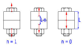
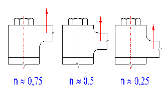
Whilst the position of the point of action of the operational force is quite obvious with some connections, such positions are more intuitive with other connections and its exact determination may be quite difficult. The existence of two limiting conditions, between which reality can be found, is a certain guideline. If determination of the coefficient of implementation of the operational force is not obvious from the geometry of the connection, it is presupposed as n=0.5 in connections with bolts through and n=0.75...0.25 according to the design of the connection in connections with stud bolts.
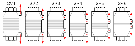
More precise values of the factor of implementation of operational force can be obtained e.g. from the following table according to VDI 2230:
| b / L | a / L | Type of design of the bolt connection | |||||
| SV1 | SV2 | SV3 | SV4 | SV5 | SV6 | ||
| 0.00 | 0.00 | 0.70 | 0.57 | 0.44 | 0.42 | 0.30 | 0.15 |
| 0.10 | 0.55 | 0.46 | 0.37 | 0.34 | 0.25 | 0.14 | |
| 0.30 | 0.30 | 0.30 | 0.26 | 0.25 | 0.22 | 0.14 | |
| 0.50 | 0.13 | 0.13 | 0.12 | 0.12 | 0.10 | 0.07 | |
| 0.10 | 0.00 | 0.52 | 0.44 | 0.35 | 0.33 | 0.24 | 0.13 |
| 0.10 | 0.41 | 0.36 | 0.30 | 0.27 | 0.21 | 0.12 | |
| 0.30 | 0.22 | 0.21 | 0.20 | 0.16 | 0.15 | 0.10 | |
| 0.50 | 0.10 | 0.10 | 0.09 | 0.08 | 0.07 | 0.06 | |
| 0.20 | 0.00 | 0.34 | 0.30 | 0.26 | 0.23 | 0.19 | 0.11 |
| 0.10 | 0.28 | 0.25 | 0.23 | 0.19 | 0.17 | 0.11 | |
| 0.30 | 0.16 | 0.16 | 0.15 | 0.12 | 0.12 | 0.09 | |
| 0.50 | 0.07 | 0.07 | 0.07 | 0.06 | 0.06 | 0.06 | |
| 0.30 | 0.00 | 0.16 | 0.16 | 0.16 | 0.14 | 0.14 | 0.10 |
| 0.10 | 0.14 | 0.14 | 0.14 | 0.13 | 0.13 | 0.10 | |
| 0.30 | 0.12 | 0.12 | 0.12 | 0.10 | 0.10 | 0.08 | |
| 0.50 | 0.04 | 0.04 | 0.04 | 0.03 | 0.03 | 0.03 | |
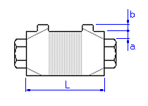
where the meaning of individual dimensions and the type of design are defined on the following illustration:
Select the corresponding joint design from the list. Special modifications of the joint are used to increase the fatigue strength of the bolt.
The way of calculation of production of the thread significantly affects the fatigue strength of the connection bolt. As far as fatigue loading, the cut thread gives the worst results. Special (additional) modifications of the threads are used to increase the fatigue strength of the bolt. You will find their description in the paragraph "Technological modifications of the connection" of the chapter "Causes of failures of bolt connections, increase in loading capacity of the bolt".
Select the required service life of the joint from the list in working cycles.
The fatigue strength of the jointing bolts declines with the increase of the number of working cycles. In the case of steel bolts, this strength declines to the level of about 106 operational cycles. In the area of required service life greater than 106 operational cycles, the material fatigue limit remains and the strength of the jointing bolt remains almost constant.
The coefficient of reliability is, in principle, a percentage of the service life and expresses the probability of trouble-free operation of the connection. In mechanical engineering, reliability is usually considered to be between 80 and 99.9%. A value of desired reliability higher than 99.9% is used only with very important equipment, whose failure could pose a threat to human lives or high material losses. In case of common bolt connections with a variable loading, the value of reliability between 95 and 99.5% is usually chosen.
|
Reliability |
Importance of the connection |
| < 90 % | Non-important connections whose failures have no particular consequences. |
| 90 - 95 % | Less important connections whose failures cause non-functionality of the higher unit, however, not its destruction. |
| 95 - 99.9 % | Important connections whose failures cause destruction of higher units and high material losses. |
| > 99.9% | Very important connections whose failures might pose a threat to human lives or high material losses. |
It is necessary to check bolt connections loaded with variable loading regarding fatigue strength. Resistance against possible fatigue breakage of the connection bolt is considered in the resulting coefficient of dynamic safety. This level of safety evaluates the position of the bolt in view of variable tensile stress and is defined as the ratio between amplitude components of the stress of the limit cycle and the operational cycle.
With regards to the accuracy and credibitility of input data, constructional design of the connection, character of loads and quality of production and operational conditions, there is usually selected a value of dynamic safety in the range from 1.5 ... 2.5. The following safety values are recommended for connections used in a non-corrosive environment at operating temperatures up to 100 °C:
|
Safety |
Parameters of the design and connection |
| 1.5 ... 1.7 | - the constructional design of the
connection meets principles for connections exposed to variable loading
- very precise determination of force conditions and stress in the connection - perfect knowledge of material characteristics - exact following of technological procedures |
| 1.7 ... 2.0 | - less exact calculation without any experimental
verification
- lower accuracy in the production technology |
| 2.0 ... 2.5 | - unsuitable constructional design of the connection,
increasing the risk of fatigue breaks in the material
- insufficient knowledge on actual occurrence and action of external forces - use of bolts of large diameters |
Constructional principles for design of connections exposed to variable loading are given in the chapter "Causes of failures of bolt connections, increasing loading capacity of bolts".
The calculation allows users to design a prestressed bolt connection of up to five parts using different materials. This paragraph can be used for a description of the geometry and selection of materials of the connected parts.
It is necessary to know the stiffness of the connected parts to determine force conditions in a prestressed bolt connection. In view of calculating stiffness, the design of connections can be divided into two basic model situations:
Select the design of the connection part in the selective list. In case of connection of cylinder parts you must also enter their diameters [3.3].
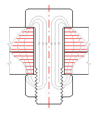
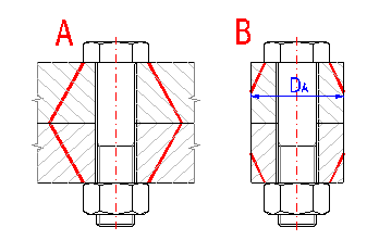
Select the number of clamped parts in the selective list. Define their dimensions in the table [3.6].
The total height of the clamped parts is considered as the distance between the head of the bolt and the nut. If the bolt connection is provided with washers, it is necessary to include the thickness of the washers in the total clamping height.
Enter the height and material of the clamped parts in the table. The connected parts are arranged in the table successively going down from the head of the bolt.
The meaning of parameters in the table:
| Li | Height of the part [mm, in] |
| E | Modulus of elasticity in tension [MPa, ksi] (at temperature 20°C, 68°F) |
| a | Coefficient of thermal expansivity [10-6/°C, 10-6/°F] (for warming 20->100°C, 68->212°F) |
| pA | Permitted pressure [MPa, ksi] |
| Material | Select a suitable material from the pop-up list |
The first five rows of the list is reserved for materials defined by the user. Information and settings of proper materials can be found in the document "Workbook (calculation) modifications". Other rows of the list include a selection of materials for the actually specified standard in the sheet "Material".
This paragraph can be used for selection of material and design of suitable dimensions of bolts for the above-mentioned specified design and loading of a prestressed bolt connection. The connection bolt can be designed manually, or use the automatic design function using the pushbutton in the row [4.13].
Values of minimum diameters of the thread are calculated additionally in the table depending on various combinations of materials of bolts and types of threads. Each column of the table concerns the specified material of the bolt and each row concerns the specified thread. Individual strength classes of bolts are selected according to the standard and specified in a list of standards [4.1]. The used specification of the type of thread has the following meaning:
| MC | Metric thread, coarse |
| MF | Metric thread, fine |
| UNC | Inch thread, coarse |
| UNF | Inch thread, fine |
| UNEF | Inch thread, extra fine |
Material of the connection bolt can be selected in the pop-up list in the row [4.4]. The table "recommended diameters of the thread" [4.2] can be used as a guideline for selection of a suitable material. The first five rows of the list are reserved for materials defined by the user. Information on setting proper materials can be found in the document "Workbook (calculation) modifications". Other rows of the list include the selection of materials for the actually specified standard [4.1].
For stud bolts, enter the tensile modulus of elasticity of the material of the stud part of the joint at assembly temperature.
This part can be used for selection of the type and dimensions of the thread of the connection bolt. Select the type of thread in the list [4.12]. The first five items of the list are reserved for standardized threads. Select the desired nominal size of the thread for the selected type of thread in the list [4.14]. Other necessary dimensions of the thread [4.15 to 4.18] are calculated automatically according to the standard. For a design of suitable size of the thread you can use the pushbutton [4.13] for automatic design of the connection bolt.
In case you wish to use a bolt with another (special) type of thread in the connection, select the last item in the list [4.12] and in input fields [4.15 .. 4.18] enter all necessary dimensions of the thread.
Start automatic design by pressing the appropriate button in the line [4.13]. Using the "F0min" button, search for the suitable bolt dimensions for the minimum assembly prestressing that ensures the required functionality of the joint. When using the "F0max" button, a bolt is sought for maximum assembly prestressing, which corresponds to the "Tightening factor" defined in the line [8.3].
In case of automatic design, a bolt of the minimum dimensions for the selected material of the bolt [4.4] and the type of the thread [4.12] is selected so that the desired functionality of the connection is ensured and the bolt meets specifications of the desired level of safety [2.4] in view of strength resp. [2.26]. The application provides a design only for prismatic bolts of constant diameters (see [4.19]) with inter-circular contact surface [4.30]. Furthermore, the design also automatically includes dimensions of seating surfaces of the head and the diameter of the hole for the connection bolt (see [4.29]). If the application does not find a suitable bolt, this fact is indicated by a warning message.
The most frequent causes of insufficient designs and their possible solutions:
Sometimes it may be suitable, from a technological or constructional viewpoint, to use a special bolt in the connection instead of a common prismatic bolt with several different cross- sections. For example in cases of request for accurate connection of the parts using fitted bolts or when using the connecting bolt with shortened stem to reduce the influence of the additional bending tensions. Pliable bolts with special treatment are also frequently used with connections exposed to a variable loading.
This paragraph can be used to define these special bolts. The number of sections of a bolt with different cross-sections is entered in the row [4.23], the length and diameter of the particular section is defined in rows [4.26, 4.27]. Individual sections of the bolt are numbered in increasing order from the nut of the bolt.
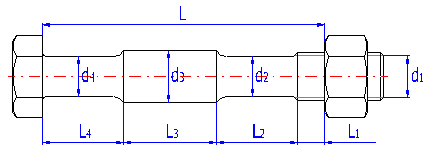
This part can be used to set the shape and dimensions of the seating surface of the head (nut) of the bolt and to determine the diameter of the hole for the connection bolt. When the check mark in the row [4.30] is enabled, all necessary dimensions are set automatically according to the following rules:
In case of bolt connections, three basic types of designs of seating surfaces below heads (nuts) of bolts are used.

In this paragraph you can find force conditions acting in the designed prestressed bolt connection. Constants of stiffness of the connection are first calculated additionally in the first part [5.1]. Once the constants have been calculated, the necessary mounting prestressing of the connection and the corresponding tightening moment are designed in the second part [5.6]. The force conditions in a fully loaded bolt connection for the given mounting prestressing are calculated additionally in the last part [5.15]. The force conditions are shown in the illustration in the lower part of this paragraph.
Constants of stiffness express the linear dependence between the axis force acting in the connection and the deformations of individual parts of the bolt connection caused by this force. The constants are considered as guide data for determination of force conditions of the prestressed bolt connection. Distribution of actions of external axial force between the connection bolt and the clamped parts of the connection is determined depending on the ratio of the resulting stiffnesses [5.4, 5.5]. The resulting stiffnesses are determined using the stiffnesses [5.2, 5.3] based on the selected factor of implementation of the operational force [2.17].
Determination of "correct" mounting prestressing is one of the main tasks in the design of a prestressed bolt connection. A sufficient amount of mounting prestressing is decisive for correct functioning of the connection. At the same time, this also affects the resulting force acting in the connection bolt, hence the level of safety against a possible breakage of the bolt. The mounting prestressing must be designed to ensure the requirement of compactness or tightness of the connection in case of connections loaded in the axis of the bolt, and the requirement of shear loading capacity of the connection in case of connections loaded in the plane of the connected parts.
Mounting prestressing can be designed manually or an automatic design can be used. The automatic design can be initiated if the check mark box to the right of the input field is enabled. The programme then provides a design for the minimum mounting prestressing to meet the above-mentioned requirement of compactness or shear loading capacity of the connection. The condition of compactness of the connection is considered as fulfilled if the coefficient of prestressing of the connection [5.21] is higher or equal to the desired value [2.1]. For fulfilling of the condition of shear loading capacity of the connection, the safety against side shift [5.22] must be higher or equal to the desired safety [2.2].
In the course of tightening (prestressing) of the connection, the bolt in the connection elongates and at the same time, the clamped parts are squeezed. The ratio between deformation of the bolt and deformation of the clamped parts is given by the ratio of their particular stiffnesses. After implementation of the axis operational force into the connection, the loading of the clamped parts is reduced and the loading of the connection bolt is increased. For the purpose of a strength check, it is therefore necessary to determine the maximum internal axis force acting on the bolt. The mounting diagram of the connection is used for this purpose.
The mounting diagram of the connection is compiled for known prestressing and stiffness values of individual elements of the connection. Distribution of the action of external axial force between the connection bolt and the clamped parts of the connection is determined using this diagram.
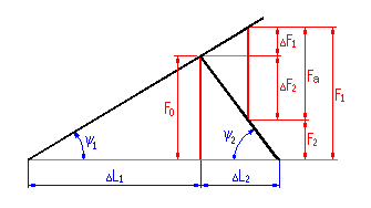
where:
F0 - mounting prestressing of the connection
DL1 - deformation (elongation) of the
bolt due to mounting prestressing
DL2 - deformation (squeezing) of the
clamped parts due to mounting prestressing
c1 = tg y1 -
constant of stiffness of the bolt
c2 = tg y2 -
constant of stiffness of the clamped parts
Fa - maximum operational axial force loading
the connection
DF1 - the part of the axis component of
the operational force additionally loading the bolt
DF2 - the part of the axis component of
the operational force relieving the clamped parts
F1 - maximum internal axial force in the bolt
F2 - residual prestressing of clamped parts of the connection
The given diagram is compiled with the presupposition that the points of inputs of the external axial loading are situated at the ends of the clamping length, in seating surfaces below the head and nut of the bolt. However, in reality the axial forces act usually on points situated inside the clamped parts (see The factor of implementation of the operational force [2.17]). This causes changes in the ratio of stiffness between the loaded and relieved parts of the connection, hence changes in the angles y1 a y2.
This coefficient gives the ratio between the residual prestressing of the clamped parts of the connection [5.19] and the maximum axis operational force [5.7]. Detailed information can be found in [2.1].
This coefficient of safety gives the ratio between the actual residual prestressing in the connection [5.19] and the minimum (theoretically calculated) clamping force [5.9] necessary for full transfer of the radial force. Detailed information can be found in [2.2].
This paragraph gives results of basic strength checks of the bolt connection.
The strength check is executed by comparing the resulting reduced stress in the bolt core [6.6] with the yield point of the material of the bolt [6.7]. The resulting reduced (comparative) stress is calculated in the thinnest part of the bolt (for prismatic bolts for small diameter threads, in the weakened shaft with pliable bolts).
The reduced stress is calculated according to the formula:

where:
s - tensile stress in the bolt core for
the maximum axis force
sb - additional bending stress
t - torsional stress in the bolt core for
the tightening torsional moment
kt - reduction coefficient (see the chapter "Setting, change the language")
If the designed bolt has to meet all requirements of the strength check, the resulting level of safety [6.8] must be higher or equal to the desired level of safety [2.4].
The strength check is executed by comparing the resulting reduced stress in the bolt core [6.12] with the yield point of the material of the bolt. According to the general recommendations, the comparative stress should not exceed 90% of the yield point.
The reduced stress is calculated according to the formula:

where:
s0 - tensile stress in the bolt core for the assembly preload
sb - additional bending stress
t - torsional stress in the bolt core for
the tightening torsional moment
If the designed bolt connection has to meet specifications of the check, the pressure in the seating surface [6.15] must be lower than the permitted pressure in the marginal connected part [6.16]. If the designed connection does not meet the specifications, modify the design so that the head (nut) seating surface is enlarged.
If there is a decline in the prestressing of the joint due to temperature change [5.16] or subsidence of a joint [5.17], the bolt may be exposed short-term to a substantially higher load than the one for which it was tested in the paragraph [6.1]. In such case, it is suitable to also consider testing the bolt for this maximum load. The peak of the resultant stress should then not substantially exceed the yield point of the bolt material.
A bolt connection exposed to variable loading must be checked in view of fatigue strength. Fatigue breaks usually appear on bolts at points of stress concentrations (in places of constructional notches), most frequently in the section of the first load carrying thread.
The procedure of determining dynamic safety of the connection and the meaning of the rows [7.2 .. 7.10] is obvious in the following illustrations:
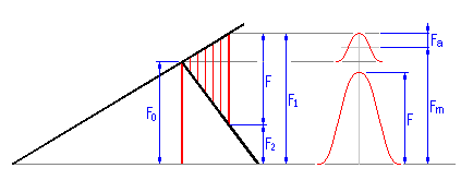
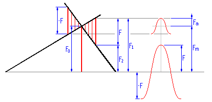
where:
F - maximum axial force loading the connection
F0 - prestressing of the connection
F1 - maximum internal axial force in the bolt
F2 - minimum residual prestressing of the clamped parts of the
connection
Fm - medium axis force of the cycle
Fa - amplitude of the axis force of the
cycle
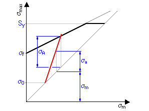
where:
Sy - yield point of the material of the bolt
sf -
fatigue limit
s0 - stress in the thread core
from prestressing of the connection
sA - amplitude component of
limit fatigue strength of the bolt for the given course of loading
sm -
medium stress of the operational cycle in the thread core
sa -
amplitude component of the stress of the operational cycle in the thread core
Also in case of a dynamically loaded connection, the designed bolt must meet requirements of the "static" check at the yield point for loads from the maximum axis force [6.1].
Resistance against a possible fatigue break of the connection bolt is considered on the basis of the resulting coefficient of dynamic safety [7.10]. This level of safety evaluates the position of the bolt in view of variable tensile stress and is defined as the ratio between amplitude components of the stress of the limit cycle sA and the operational cycle sa. If the designed bolt has to meet all requirements of the strength check, the resulting safety level [7.10] must be higher or equal to the desired safety level [2.26].
Theoretically calculated fatigue limit in tension of a smooth rod with a circular diameter of the selected material of the bolt, loaded with an alternate axial loading.
Fatigue limit in tension of the designed bolt material for the desired service life of the connection [2.24].
Fatigue limit in tension of the designed bolt. Corrected value of the basic fatigue limit [7.7] with regards to the selected design of the connection [2.22, 2.23], type and dimensions of thread [4.11] and desired reliability of the connection [2.25].
In the case of shoulder bolts, a fatigue fracture sometimes occurs at the point of transition to the reduced shank.
This strength test is done according to the same principles as the test in the thread core. The corrected fatigue limit [7.14] shall however be higher in the case of this test. If the designed bolt has to meet all requirements of the strength check, the resulting safety level [7.16] must be higher or equal to the desired safety level [2.26].
Fatigue limit in tension of the designed bolt. Corrected value of the basic fatigue limit [7.7] with regards to the selected geometry of the bolt [4.19] and desired reliability of the connection [2.25].
In the main calculation, the theoretical values of the necessary assembly prestressing and tightening torque are additionally calculated for the designed screw joint. In real-time practice, it is however very difficult and costly to achieve a precise assembly prestressing in a joint when tightening a bolt.
For this reason, the screw joints are often designed to ensure their correct functionality for a given, predefined assembly prestressing range <F0min...F0max>. The width of this range at the same time shall depend on the applied bolt tightening method. This paragraph is just intended for testing screw joints of such design.
The permissible prestressing range is determined using the "Tightening factor" [8.3]. The lower prestressing limit "F0min" at the same time must ensure the requirement of the compactness of the joint during operation. For the upper limit of the assembly prestressing "F0max", the bolt must fulfil the conditions of the strength test.
This coefficient gives the ratio between the upper and lower limit of the permissible assembly prestressing aA=F0max/F0min.
The coefficient may assume values in the interval <1-4> and its size shall depend on the applied bolt tightening method.
| aA | Tightening method | Setting method |
| 1.05 to 1.2 | Tightening with elongation control or monitoring by ultrasound. | Sound travel time. |
| 1.1 to 1.3 | Mechanical elongation by means of pressure screws located in the nut or the bolt head. | Prespecified elongation of the bolt, setting via forcing torque of the pressure screws. |
| 1.2 to 1.5 | Mechanical elongation by means of multipartite nuts with threaded bushing. | Torque of the tightening tool. |
| 1.1 to 1.5 | Tightening with mechanical elongation measurement or monitoring. | Setting via adjustment measurement. |
| 1.1 to 1.4 | Continual hydraulic tightening. | Setting via pressure or length measurement or rotation angle of the nut. |
| 1.2 to 2.0 | Impulse driver with hydraulic impulse generator, torque and/or angular displacement controlled. | Setting via angle of rotation or torque. |
| 1.2 to 1.4 | Yield-point controlled tightening, motorized or manual. | Presetting of the relative torque or rotation angle coefficient. |
| 1.2 to 1.4 | Rotation-angle controlled tightening, motorized or manual. | Experimental determination of preliminary tightening moment and rotation angle. |
| 1.4 to 1.6 | Torque-controlled tightening with hydraulic tool. | Setting via pressure measurement. |
| 1.4 to 1.6 | Torque-controlled tightening with torque wrench, signalling wrench or motorized nut-runner with dynamic torque measurement. | Experimental determination of the required tightening torque at the original joint member (for example, by elongation measurement of the bolt). |
| 1.6 to 2.0 | Torque-controlled tightening with
torque wrench, signalling wrench or motorized nut-runner with dynamic torque
measurement. For friction coefficient m=0.08~0.16 |
Determination of the required tightening torque by estimating the friction coefficient (surface and lubricating conditions are a great influence). |
| 1.7 to 2.5 | Torque-controlled tightening with
torque wrench, signalling wrench or motorized nut-runner with dynamic torque
measurement. For friction coefficient m=0.04~0.10 |
|
| 2.5 to 4.0 | Tightening with impact wrench or
impulse driver.
Tightening by hand. |
Setting the driver via retightening
moment, which is formed from the required tightening moment (for the
estimated coefficient of friction) plus supplement. Manual tightening based on subjective assessment. |
This paragraph is used to investigate the force ratios in the joint at a specific working temperature.
The working joint prestressing changes upon change of the working temperature. This change is caused by two different phenomena:
Change in temperature also results in change of the physical and mechanical properties of the materials used. For correct design of the joint, it is therefore necessary to know the properties of the material at working temperature. Enter the corresponding values in paragraphs [9.5] and [9.9].
Information on options of 2D and 3D graphic outputs and information on cooperation with 2D and 3D CAD systems can be found in the document "Graphic output, CAD systems".
For drawing the bolt connection it is necessary to set in this paragraph some details of the connection which were not determined with calculations of the connection.
Select the respective design of the bolt head in the selective list. The application provides 4 basic designs of bolt heads. However, with regards to commonly produced sizes of bolts, it is not possible to use all these types of heads for some diameters of threads. The dimensions of the selected head are determined using the selected type and diameter of thread [4.12, 4.14] according to the following standards: ANSI B18.2.1, ANSI B18.3, ANSI B18.6.2, ANSI B18.6.3, ISO 1207, ISO 4016, ISO 4762.
Select the respective design of the bolt nut in the selective list. The application provides 2 designs of hexagonal nuts. The dimensions of the selected nut are determined using the selected type and diameter of thread [4.12, 4.14] according to the standards: ANSI B18.2.2, ISO 4032, ISO 4035.
In the selective list, specify the number of washers below the bolt head. If the drawing has to include a connection without washer, select "0". The dimensions of the washer are determined using the selected type and diameter of thread [4.12, 4.14], according to the standards: ANSI B18.22.1, ISO 8738.
In the selective list, specify the number of washers below the nut. If the drawing has to include a connection without washer, select "0". The dimensions of the washer are determined using the selected type and diameter of thread [4.12, 4.14], according to the standards: ANSI B18.22.1, ISO 8738.
Solution - Suitable technological and constructional modifications to increase the loading capacity of the bolt (described in detail in the following chapter).
Fatigue breaks occur in parts exposed to variable loading, usually at points of stress concentration (in places of constructional notches), though the value of the nominal stress is well below the ultimate strength. Statistics shows that of the total number of evaluated standardized bolts, breaks occur in 65% of bolts at the point of the first load carrying thread, in 20% at the run-out of the thread and in 15% at the place of the transition of the shaft into the head of the bolt. The above-mentioned classification of frequencies of fatigue breaks shows some evident critical points which must be taken into account with designs of dynamically loaded connections.
Constructional modifications of the connection:
Use of a tractive nut or a nut with a relieving notch.
Distribution of the stress between the thread will be improved and the first
load carrying thread will be relieved.
Carry out the first load carrying thread of the bolt and the very first
thread, with a transition into a reduced shaft and an overlap of the nut
thread.
The first load carrying thread will be relieved and the notch coefficient in
the run-out of the thread will be decreased.
Decreasing the notch coefficient in the run-out of the thread with a rounded transition into a shaft with a reduced diameter.
Increasing the transition radius from the head to the shaft.
If possible, do not use threads with fine spacing.
If possible, do not use bolts of large diameters.
It is advisable to use two smaller bolts instead of one big bolt.
Suitable constructional design of connections with stud bolts.
It is advisable to design a connection with overlapping threads of the bolts
in open holes. In case of blind holes, it is better to use a stud bolt with
a nut bearing against the hole bottom instead of a common bolt with a head.
The most advantageous case is to use a stud bolt with a ball end or a small
ball inserted.
Technological modifications of the connection:
Use of a rolled thread instead of a cut thread.
Additional rolling of the thread root.
Hardening of the material using cold forming.
Chemical and thermal treatment of the thread, nitriding, phosphating.
Bolt connections often do not occur individually, but in groups, where they provide combined transfer of external forces. Due to technological reasons the fields mostly include bolts of the same diameters, arranged in rectangular or circular shapes. The solution of these group connections is based on determination of the maximum load falling on one (concurrently or the most loaded) bolt, which is then designed as an independent bolt connection according to the above-mentioned procedures.
There are also given general procedures of solutions for several basic types of bolt fields (the symbol "n" used in the formulas indicates the number of bolts in the connection):
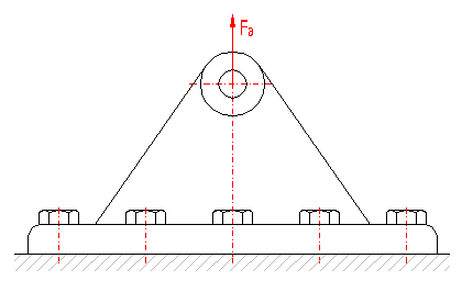
The external loading is distributed uniformly to all bolts of the connection.
Axial loading falling on one bolt:
![]()
The group connection is then designed as an independent bolt connection exposed to the axial force Fai.
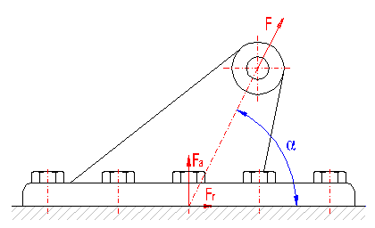
The external force is decomposed into component Fa, perpendicular to the contact surface, and component Fr, parallel to it. The connection bolts will be loaded uniformly, thus:
Axial loading falling on one bolt:

Radial loading falling on one bolt:

The group connection is then designed as an independent bolt connection exposed to a combined loading from the axis force Fai and the cross force Fri.
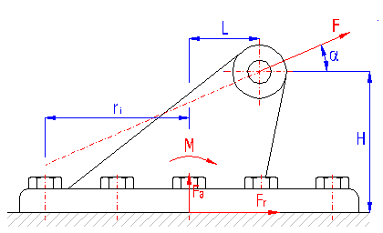
The external force is decomposed into component Fa perpendicular to the contact surface and component Fr parallel to it, acting on the centre of gravity of the connection:
![]()
At the same time, it also creates a moment on the centre of gravity:
![]()
The condition of non-deviation of the left margin of the basic plate causes the minimum needed stress:

where e.g. for a rectangular contact surface the contact surface "A" of the connection and the sectional module "W" can be determined using the relations:

where:
a - length of the connection
b - width of the connection
When designing a connection, it is also necessary to determine maximum values of partial forces acting on one bolt.
Axis forces in bolts from force Fa:
![]()
Axis forces in bolts from moment M:
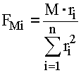
Maximum axis force in the bolt from moment M:
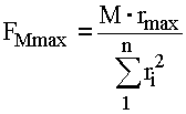
Total maximum axis operational force:
![]()
Radial forces in bolts from component Fr:
![]()
The group connection is then designed as an independent bolt connection exposed to combined loading from axis force Famax and cross force Fri. It is also necessary not to forget to check the designed prestressing of the connection [5.17] with regards to minimum necessary prestressing F0min, determined using the condition of non-deviation of the margin of the basic plate.
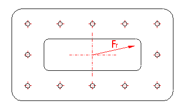
The external loading is distributed uniformly to all bolts of the connection.
Radial loading falling on one bolt:
![]()
The group connection is then designed as an independent connection exposed to cross force Fri.
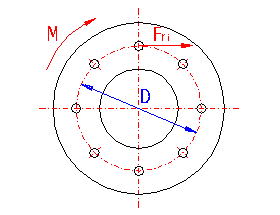
If circular flanges are exposed to a torsional moment only, individual bolts will be exposed uniformly to the radial force:

The group connection is then designed as an independent bolt connection exposed to cross force Fri.
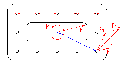
The cross force acting in the centre of gravity of the connection is distributed uniformly to all bolts:
![]()
The torsional moment causes loading of each individual bolt by a radial force:

The resulting force acting on one bolt is a vector sum of partial forces Fri, FMi. The group connection is further designed as an independent bolt connection exposed to maximum cross force Frmax.
Information on setting of calculation parameters and setting of the language can be found in the document "Setting calculations, change the language".
In this paragraph, you can set some of the basic parameters for the behaviour of the calculation (applied calculation procedures). By selection of suitable theoretical calculation models, you can thus adapt the calculation to your individual practice.
The rigidity constants are the basic data item for determination of the force ratios of the prestressed screw joint. While it is possible by standard mathematical methods to calculate the rigidity constants of bolts with relative precision, the situation is different when determining the rigidity of the clamped parts and it is hardly possible to get precise rigidity values by procedure other than by experimental measurement.
When tightening the screw joint, the stress between the head and nut spreads in an asymmetric area, whose sectional dimensions change along the clamping length. It is very difficult or even impossible to create a general mathematical model that precisely describes this area. In the past, many various calculation models were thus created that are based on many simpler assumptions. The results of these models may differ substantially. For this reason, the program offers a possibility to choose from five historically most commonly used calculation procedures. For calculation of the rigidity of clamped parts, these mathematical models use two basic methods:
Substitute tube method - The older and simpler method in which for the purpose of calculation of the stress, the afflicted area is replaced by an imaginary thick-walled tube.
Pressure cone method - More modern and precise method based on the idea that the area afflicted by stress has the approximate shape of a truncated double cone.
Enter the angle of the pressure cone.
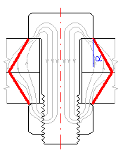
According to "Shigley", this angle changes in the range 25-33° in relation to the geometry and material of the joint. Usually, precision of 30° is considered suitable.
Theoretically the strength test of the stressed part is always done at its narrowest point. For a strength test of a bolt, the critical cross-sectional area should thus correspond to the cross-section of the thread core. However, a large number of strength tests has shown that in the case of standardized threads, the factual critical cross-sectional area is larger. This area is usually termed the "Tensile stress area" and its section corresponds to the arithmetic mean from the centre and small diameter of the thread.
The tightening of the bolt creates torsional stresses in the thread core, which must be taken into account during strength testing of the bolt. The size of this stress in the bolt core declines over time. During the strength test of the joint in operating state, it is thus suitable to count on a lower torsional stress than during testing of the joint in the assembled state.
The reducing coefficient gives the size of the torsional stress that will be part of the total stress in the bolt core under working load. The resulting comparative stress in working state is then determined using the formula:

where:
s - tensile stress in the bolt core for
the maximum axis force
sb - additional bending stress
t - torsional stress in the bolt core for
the tightening torsional moment
kt - reduction coefficient
The reduction coefficient may have values in the interval <0..1>. For variable "0", the torsional stress is completely neglected and the bolt is tested only in terms of tensile stress (a method usually used in literature in the USA). For variable "1", the strength test on the contrary includes the total size of the torsional stress from the tightening torque (this procedure favours safety and is often stated in older European literature).
General information on how to modify and extend calculation workbooks is mentioned in the document "Workbook (calculation) modifications".
^