The program is designed for design and control of hydrodynamic radial plain bearing. In the program it is possible to solve other tasks such as lubricant viscosity, shaft and bearing fit tolerances, parameters of friction materials, calculation of bearing clearance, etc.
The program includes and addresses the following:
1. Design of radial plain bearing dimensions based on load and operating
conditions
2. Control calculation of various types of bearings
3. Bearing clearance design and calculation of bearing and shaft tolerances
4. Proposal of suitable lubricant, oil database, viscosity calculations
5. Calculation of operating temperatures, coefficient of friction, lubricant
flow and other parameters
6. Database of sliding materials and their parameters
The calculation is based on data, procedures and algorithms from specialized literature, standards and company catalogues.
[1] Strojně technická příručka (Svatopluk Černoch)
[2] Shigley’s Mechanical Engineering Design
[3] Strojírenská
příručka (1992)
[4]
Machinery’s Handbook
(26th Edition)
[5] Části a mechanismy strojů II
[6] Tribologie (Jan Bečka)
Standards: ISO 7902, DIN 31652, ISO 2909, ISO 3448, ISO 3547, ISO 12129, ISO 4381, ISO 4382 , ISO 2909, ISO 3448, DIN 504
Company catalogues: SKF, FAG, INA, Timken, RBC Bearings Incorporated, Tecnamic GmbH...
User interface.
Download.
Purchase, Price list.
Information on the syntax and control of the calculation can be found in the document "Control, structure and syntax of calculations".
Information on the purpose, use and control of the paragraph "Information on the project" can be found in the document "Information on the project".
The function of the plain bearing is based on the use of fluid friction between the shaft and bearing (or friction segment and pressure plate in the case of thrust bearings). When the shaft and bearing move together, the lubricant is drawn into the narrow gap between the bearing and shaft. This creates a thin film of lubricant that separates the bearing and shaft and causes fluid friction. The creation and maintenance of fluid friction is dependent on numerous parameters. Starting with dimensions, choice of materials, surface quality, choice of lubricant, etc. See figure (f...coefficient of friction, v...sliding speed).
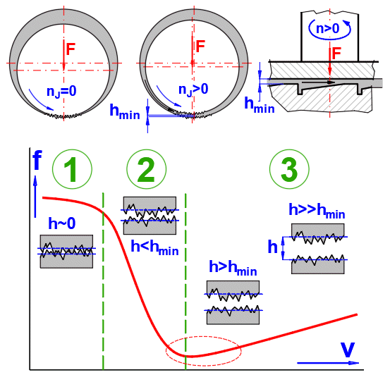
1. Steady state / Dry friction
2. Low speed / Mixed friction
3. High speed / Liquid friction
The calculation is used to control (suggest) whether the bearing, under steady operating conditions, operates in the fluid friction range.
Due to the importance of plain bearings, this issue is addressed in a number of professional publications and standards. The calculation results are comparable for normal use. Therefore, we use the procedures defined by ISO 7902 - journal bearings, ISO 12131, ISO 12130 - plain thrust pad bearings (and related ISO standards) in our calculations. The ISO standard is comparable to DIN 31652, DIN 31654..... The calculations are extended with some additional parameters and recommendations based on professional and company literature.
| EN | Table - Symbols and their designations | |
| Symbol | Designation | Unit |
| ISO 7902 - 1, 2 | ||
| A | Area of heat-emitting surface (bearing housing) | m² |
| bG | Width of lubrication groove | m |
| bP | Width of lubrication pocket | m |
| B | Nominal bearing width | m |
| BH | Length of the axial housing | m |
| cp | Specific heat capacity of the lubricant | J/kg/°K |
| C | Nominal bearing clearance | m |
| CR,eff | Effective bearing radial clearance | m |
| dL | Lubrication hole diameter | m |
| D | Nominal bearing diameter (inside diameter) | m |
| DH | Outside diameter of the housing | m |
| DJ | Nominal shaft diameter | m |
| DJmax | Maximum value of DJ | m |
| DJmin | Minimum value of DJ | m |
| Dmax | Maximum value of D | m |
| Dmin | Minimum value of D | m |
| e | Eccentricity between the axis of the shaft and the bearing axis | m |
| f | Coefficient of friction in the loaded area of the lubricant film (f= Ff/F) | [~] |
| f' | Coefficient of friction in both the loaded and unloaded area of the lubricant film | [~] |
| F | Bearing force (nominal load) | N |
| Ff | Friction force in the loaded area of the lubricant film | N |
| Ff' | Frictional force in both the loaded and the unloaded area of the lubricant film | N |
| h | Local lubricant film thickness | m |
| heff | Effective lubricant film thickness | m |
| hG | Depth of lubrication groove | m |
| hlim | Minimum permissible lubricant film thickness | m |
| hmin | Minimum lubricant film thickness | m |
| hp | Depth of lubrication pocket | m |
| H | Length of the total height of the pedestal bearing | m |
| kA | Outer heat transmission coefficient | W/m²/°K |
| NB | Rotational frequency of the bearing | /s |
| NJ | Rotational frequency of the shaft | /s |
| NF | Rotational frequency of the force F | /s |
| p | Local lubricant film pressure | Pa |
| p' | Specific bearing load | Pa |
| pen | Lubricant feed pressure | Pa |
| plim | Maximum permissible lubricant film pressure | Pa |
| plim' | Maximum permissible specific bearing load | Pa |
| Pf | Frictional power | W |
| Pf' | Frictional power in both the loaded and the unloaded area of the lubricant film | W |
| Pth | Heat flow rate | W |
| Pth,amb | Heat flow rate to the ambient | W |
| Pth,f | Heat flow rate due to frictional power | W |
| Pth,L | Heat flow rate in the lubricant | W |
| qL | Coefficient related to lubricant flow rate due to feed pressure | [~] |
| qP | Coefficient related to lubricant flow rate from pocket | [~] |
| Q | Lubricant flow rate | m³/s |
| Q3 | Lubricant flow rate due to hydrodynamic pressure | m³/s |
| Q3* | Lubricant flow rate parameter due to hydrodynamic pressure | [~] |
| Qp | Lubricant flow rate due to feed pressure | m³/s |
| Qp* | Lubricant flow rate parameter due to feed pressure | [~] |
| RzB | Average peak-to-valley height of bearing sliding surface | m |
| RzJ | Average peak-to-valley height of shaft mating surface | m |
| Re | Reynolds number | [~] |
| So | Sommerfeld number | [~] |
| Sou | Transition Sommerfeld number | [~] |
| Tamb | Ambient temperature | °C |
| TB | Bearing temperature | °C |
| TB,0 | Assumed initial bearing temperature | °C |
| TB,1 | Calculated bearing temperature resulting from iteration procedure | °C |
| Teff | Effective lubricant temperature | °C |
| Ten | Lubricant temperature at bearing entrance | °C |
| Tex | Lubricant temperature at bearing exit | °C |
| Tex,0 | Assumed initial lubricant temperature at bearing exit | °C |
| Tex,1 | Calculated lubricant temperature at bearing exit | °C |
| TJ | Shaft temperature | °C |
| Tlim | Maximum permissible bearing temperature | °C |
| TL' | Mean lubricant temperature | °C |
| UB | Linear velocity (peripheral speed) of bearing | m/s |
| UJ | Linear velocity (peripheral speed) of shaft | m/s |
| Va | Air ventilating velocity | m/s |
| x | Coordinate parallel to the sliding surface in the circumferential direction | m |
| y | Coordinate perpendicular to the sliding surface | m |
| z | Coordinate parallel to the sliding surface in the axial direction | m |
| αLB | Linear heat expansion coefficient of the bearing | /°K |
| αLJ | Linear heat expansion coefficient of the shaft | /°K |
| β | Attitude angle (angular position of the shaft eccentricity related to the direction of load) | ° |
| ε | Relative eccentricity [ε = 2e/(D — DJ)] | [~] |
| εu | Transition eccentricity | [~] |
| η | Dynamic viscosity of the lubricant | Pa.s |
| ηeff | Effective dynamic viscosity of the lubricant | Pa.s |
| ν | Kinematic viscosity of the lubricant | m²/s |
| ξ | Coefficient of resistance to rotation in the loaded area of the lubricant film | [~] |
| ξ' | Coefficient of resistance to rotation in both the loaded and the unloaded area of the lubricant film | [~] |
| ξG | Coefficient of resistance to rotation in the area of circumferential groove | [~] |
| ξP | Coefficient of resistance to rotation in the area of the pocket | [~] |
| Rho | Density of lubricant | kg/m³ |
| Rho20 | Density of lubricant at 20°C | kg/m³ |
| φ | Angular coordinate in the circumferential direction | rad |
| φ1 | Angular coordinate of pressure leading edge | rad |
| φ2 | Angular coordinate of pressure trailing edge | rad |
| ψ | Relative bearing clearance | [~] |
| ψ' | Mean relative bearing clearance | [~] |
| ψeff | Effective relative bearing clearance | [~] |
| ψmax | Maximum relative bearing clearance | [~] |
| ψmin | Minimum relative bearing clearance | [~] |
| ωB | Angular velocity of bearing | /s |
| ωF | Angular velocity of rotating force | /s |
| ωH | Hydrodynamic angular velocity | /s |
| ωJ | Angular velocity of shaft | /s |
| Ω | Angular span of bearing segment | ° |
| ΩG | Angular span of lubrication groove | ° |
| ΩP | Angular span of lubrication pocket | ° |
| ISO 7902 - 3 | ||
| E' | Dimensionless modulus of elasticity | [~] |
| G' | Dimensionless shear modulus | [~] |
| hwav | Waviness of sliding surface | m |
| hwav,eff | Effective waviness of sliding surface | m |
| hwav,eff,lim | Maximum permissible effective waviness | m |
| hwav,lim | Maximum permissible waviness | m |
| i | Number of waviness | [~] |
| IG | Length of lubrication groove | m |
| IP | Length of lubricant pocket | m |
| LH | Length of bearing housing | m |
| NF | Rotational frequency of the bearing force | /s |
| Q1 | Lubricant flow rate at the inlet to clearance gap | m³/s |
| Q2 | Lubricant flow rate at the outlet to clearance gap | m³/s |
| γ | Angle of misalignment of the shaft | rad |
| φwav | Period of waviness | ° |
| MITCalc | ||
| BD | Bearing width ratio, relative bearing width B/D | [~] |
| D1 | Bearing outside diameter | m |
| D2 | Housing outside diameter | m |
| E | Modulus of elasticity in tension (Young modulus) | Mpa |
| EI | Lower deviation | μm |
| ES | Upper deviation | μm |
| Fmax | Maximum bearing force | N |
| fo | Minimum particle size that will pass through the filter | μm |
| m | Bearing weight | kg/m³ |
| Mf | Frictional moment | Nm |
| nB | Rotational speed of the bearing | /min |
| nF | Rotational speed of the force vector | /min |
| nJ | Rotational speed of the shaft | /min |
| nm | Limit speed - Mixed-film lubrication | m/s |
| nt | Limit speed - Formation of turbulence | m/s |
| p1 | Contact pressure during bearing insertion in the bearing housing | Mpa |
| Tx | Temperature (for which the parameter is calculated) | °C |
| ya | Amount of misalignment of the shaft | m |
| yd | Amount of deflection on bearing width | m |
| βL | Thermal expansion coefficient | 1e-6/K |
| ΔDo | Mean value of the interference | m |
| Δψ(P) | Pres fitt change of the relative bearing clearence | [~] |
| Δψ(T) | Thermal change of the relative bearing clearence | [~] |
| ν | Poisson number | [~] |
| φA,φE | Angles of leading edge and trailing edge | ° |
A number of assumptions and simplifications that have been experimentally validated and are listed in the ISO (DIN) standard are used in the calculations. The formulas, relationships and explanations of the calculation deviations from the ISO standard are given here.
The following idealizing
assumptions and preconditions are made, the permissibility of which has been
sufficiently confirmed both experimentally and in practice.
a) The lubricant corresponds to a Newtonian fluid.
b) All lubricant flows are laminar.
c) The lubricant adheres completely to the sliding surfaces.
d) The lubricant is incompressible.
e) The lubricant clearance gap in the loaded area is completely filled with
lubricant. Filling up of the unloaded area depends on the way the lubricant is
supplied to the bearing.
f) Inertia effects, gravitational and magnetic forces of the lubricant are
negligible.
g) The components forming the lubrication clearance gap are rigid or their
deformation is negligible; their surfaces are ideal circular cylinders.
h) The radii of curvature of the surfaces in relative motion are large in
comparison with the lubricant film thicknesses.
I) The lubricant film thickness in the axial direction (z-coordinate) is
constant.
j) Fluctuations in pressure within the lubricant film normal to the bearing
surfaces (y-coordinate) are negligible.
k) There is no motion normal to the bearing surfaces (y-coordinate).
l) The lubricant is isoviscous over the entire lubrication clearance gap.
m) The lubricant is fed in at the start of the bearing liner or where the
lubrication clearance gap is widest; the magnitude of the lubricant feed
pressure is negligible in comparison with the lubricant film pressures.
The calculation solves two cases, namely:
1. Bearing cooling by convection
2. Bearing cooling with pressure oil
Since the problem is not directly solvable, the following successive
iteration was used:
1. The working temperature of the bearing is estimated (or the oil outlet
temperature for cooling with pressure oil)
2. The lubricant parameters are calculated from the temperature
3. Other parameters characterising the bearing function are calculated
4. The power loss (friction) is calculated and thus the working temperature of
the bearing (or the oil outlet temperature for cooling with pressure oil)
5. Based on the temperatures from points 1 and 4, the new working temperature
for point 1 is approximated and the calculation is repeated.
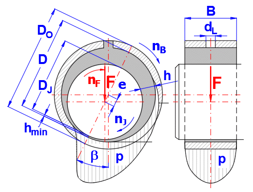
Two formulas are used to design the nominal diameter. The larger value is used.
A. Diameter providing liquid friction
D,1 = (400 * F / (n *
η * 3.14159 * BD * QualityCoeff))^(1/3)
Where QualityCoeff is in the range of 0.8-2.0 and determines the quality, accuracy and stiffness of the design.
B. Diameter for maximum permissible
specific bearing load plim
D,2 = (F / plim)^0.5 / BD^0.5
(checking if the flow is laminar)
Re = PI() * D * NJ * (ψeff * D / 2)) / (η / Rho) <= 41.3*(D / (ψeff * D))^0.5
Used formula:
Rho = Rho20 / (1 + (Tx - 20°C) * (βL / 1000))
ISO:
He doesn't specify. Requires direct input of the value Rho * cp for the operating temperature of the bearing.
DIN:
Rho = Rho20 - (Tx - 20°C) * 0.00064
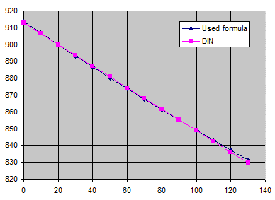
For: Rho20 = 900kg/m³, βL=0.75, X...°C, Y...kg/m³
Used formula:
cp = 4.588 * Tx - 0.005024 * Rho20^2 + 7.115 * Rho20 - 619.646
ISO:
He doesn't specify. Requires direct input of the value Rho * cp for the operating temperature of the bearing.
DIN:
Rho * cp = 1.57 + 0.003 * TempC
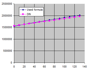
For: Rho20 = 900kg/m³, Beta=0.75, X...°C, Y...J/m³/K
Oil is defined by temperature T1, T2, kinematic viscosity v1, v2, density and by thermal expansion coefficient.
The viscosity is
calculated with use of the formulas in the standard (ASTMD341):
log(log(v + 0.7)) = A - B * log(T) ... [T...Kelvin, v...cSt, A,B ... constants]
B = {log(log(v2 + 0.7)) - log(log(v1+0.7))} / (log(T1)-log(T2))
A = log(log(v2 + 0.7)) + B * log(T2)
v = 10^(10^(A - B * log(T))) - 0.7 ... [v...Kinematic
viscosity]
η = Rho *
v
... [Rho...Density]
There are two options:
A. ISO 7902-3, Table 5 - Empirical permissible values for the mean relative bearing clearance
B.
Modiffied basic formula with diameter and pressure influence
ψ'
= (0.8 * v^0.25 + 4.5 / D^0.25 - 1.2) * (1.25 / p^0.15) * 0.001
in range <0.0008 - 0.01>
p ... Specific bearing load [MPa]
v ... Sliding speed [m/s]
D ... Nominal bearing diameter [mm]
ψeff = ψ' + ΔψT + ΔψP
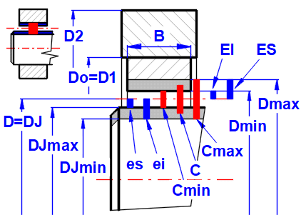
ψmax = (Dmax - DJmin) / D
ψmin = (Dmin - DJmax) / D
ψ' =
0.5 * (ψmax
+ ψmin)
C = (Cmax + Cmin) / 2
Cmin = Dmin - DJmax
Cmax = Dmax - DJmin
For coefficients of linear expansion which differ for shaft and bearing, the thermal change of the relative bearing clearance is given by:
ΔψT = (αLB - αLJ) * (Teff - 20°C)
For different T for bearing / shaft
ΔψT = αLB * (TB - 20°C) - αLJ * (TJ - 20°C)
ΔψP = - (p1 / EB) * (2 / (1 - (D / D1)²)
Characteristic parameter for the load-carrying capacity
So =(F * ψeff^2) / (D * B * η * ωH)
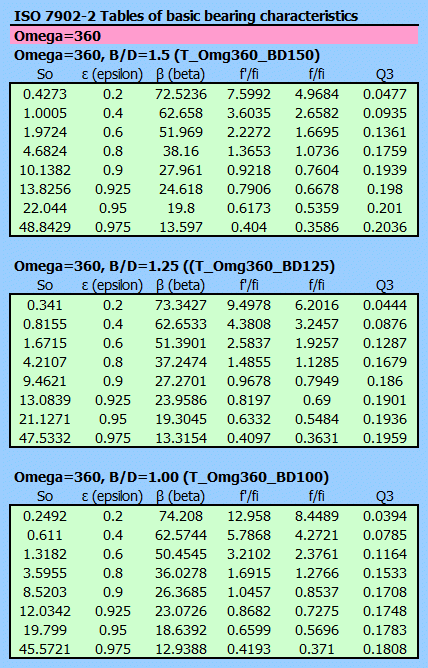
ISO 7902-2 provides
tabulated values for ε, β, f'/fi, f/fi and Q3' for the Ω angle range 90° - 360°
and for the B/D ratio in the range 0.25 - 1.5.
Interpolation is performed using Bezier interpolation.
Based on the calculated value of So, the values obtained by interpolation are as follows:
ε
(epsilon)
... Relative eccentricity [ε =
2e/(D — DJ)]
β (beta)
... Attitude angle (angular
position of the shaft eccentricity related to the direction of load)
f'/ψeff ... The specific coefficient of friction, taking account of the unloaded
area of lubricant film
f/ψeff ... The specific coefficient of friction in the loaded area of the
lubricant film
Q3'
... Lubricant flow rate parameter
due to hydrodynamic pressure
hmin = 0.5 * D * ψeff * (1 - ε)
f = (f '/ψeff) * ψeff
ωH = ωJ + ωB - 2 * ωF
Pth,f = f * F * 0.5 * D * ωH
Q3 = D^3 * ψeff * ωH * Q3'
Qp =(D^3 * ψeff^3 * pen / DynVis) * Qp'

A: Qp' = 3.14159 / 48 * (1 + ε)^3 / (LN(B / dL) * qL)
B: Qp' = 3.14159 / 48 * 1 / (LN(B / dL) * qL)
C: Qp' = 3.14159 / 48 * 2 / (LN(B / dL) * qL)
qL = 1.204 + 0.368 * (dL / B) - 1.046 * (dL / B)^2 + 1.942 * (dL / B)^3
Heat dissipation by convection. Heat dissipation by convection takes place by thermal conduction in the bearing housing and radiation and convection from the surface of the housing to the environment.
Pth,amb = kA * A * (TB - Tamb)
kA = (15 - 20) W/m²/K [without ventilation]
kA = 7 + 12 * (Va)^0.5 [Va > 0]
Should the area of the heat-emitting surface, A, of the bearing housing not be known exactly, it is possible to use approximate estimates depending on the bearing type mounting.
TB,1 = Pth,f / (kA * A) + Tamb
TB,0(i+1) = TB,0(i) + 0.2 * (TB,1 - TB,0(i))
Tex,1 = Pth,f / (Rho * Cp * Q) + Ten
Tex,0(i+1) = 0.5 * (Tex,0(i) + Tex,1)
The objective of maintaining the minimum permissible hlim thickness of the lubricating film is to maintain full lubrication of the plain bearing to achieve the lowest possible wear and low susceptibility to failure.
The lubricant should be free of contaminating particles, otherwise increased wear, seizure and local overheating may occur, thereby impairing the proper function of the plain bearing. If necessary, suitable lubricant filtration must be provided.
The minimum permissible hlim thickness of the lubricating film as a characteristic parameter for the transition to mixed friction (see ISO 7902-1:2020, 7.6) can be determined from the following formula as shown in the figure.
hlim = RzB + RzJ + f + 0.5 * B * tan(γ) + 0.5 * yd + hwav,eff

RzB,
RzJ
... Average peak-to-valley height of bearing / shaft sliding surface
f ... Mesh size of oil
filter
B ... Nominal bearing width
γ
... Angle of misalignment of the shaft
yd ... Amount of deflection
hwav,eff ... Effective waviness of sliding surface
The calculation can be used in several ways. Indicative, design and control.
Quick indicative determination of bearing size and decision between convection cooling and pressurised oil cooling.
1. Enter the basic input data [2.1-2.7]
2. Select the bearing quality level [2.8]
3. Select/set the parameters of the shaft, bearing and bearing housing materials
[2.9-2.23]
4. Press the button for Automatic design [2.25]
5. The Automatic design will attempt to estimate the remaining input parameters
based on the general recommendations
6. On lines [2.85-2.116] the functional parameters can be checked immediately
Overall design with detailed specification of all input parameters.
1. Make an indicative calculation (A)
2. Go through the input parameters [2.26-2.78] and tune the parameters you know
3. Start the temperature iteration with the ‘Iteration’ button [2.109]
4. If any of the functional parameters [2.85-2.116] do not fit, use the
Optimisation at the end of the paragraph for a quick change and check
Functional parameters check.
1. Enter the basic input data [2.1-2.7]
2. Go through the other input parameters [2.10-2.78] and define them
3. Start the temperature iteration with the ‘Iteration’ button [2.109]
In this paragraph you set the units of calculation.
Select the desired system of calculation units in the list box. After switching over the units, all values will be changed immediately.
Type the value you want to convert into the input box on the left. Select source units and target units on the right.
The Ra and Rz roughness parameters are not directly transferable.
However, based on statistical evaluation, it can be said that with a very high probability the roughness Ra(Rz) derived from the roughness Rz(Ra) will lie within the range of values in parentheses. The biggest influence is the chosen machining technology.
The formula Rz=4*Ra is used to convert the entered value
The conversion formula for:
Rz => Ra
Ramin = 0.03 * Rz^1.3
Ramax = 0.24 * Rz^1.06
Ra => Rz
Rzmin = 3.8 * Ra^0.95
Rzmax = 14.5 * Ra^0.75
The paragraph contains a complete design and control calculations.
Enter the basic input data as shown in the figure.

Enter the shaft speed, force vector and bearing.
The hydrodynamic speed, which determines the bearing function, is defined as
follows:
n=abs (nJ+nB-2*nF)
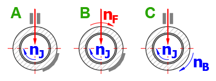
The most common examples are shown in the figure.
A. Most common case
nB=0, nF=0 ........ n=nJ
B. The load vector rotates at the same speed as the shaft (centrifugal force)
nB=0, nF=nJ ....... n=nJ
C. Shaft and bearing rotate with the same speed
nB=nJ, nF=0 ....... n = 2 * nJ (bearing load capacity is half)
The load capacity of long bearings (except sphere plain bearings) is reduced
by marginal overload (shaft deflection). The bearing has the highest load
capacity at B/D~0.4
Therefore, B/D=0.3-1.0 is generally chosen (exceptionally B/D=1.5)
Smaller values are chosen for pressure lubrication where higher oil flow does
not matter.
A number of input parameters allow selection within a certain range. Most of
the time, this choice relates to the level of manufacturing, precision, rigidity
of construction, etc.
The selection of one of the three levels from the list is taken into account in
the proposed values (green cells) and in the ‘Automatic design’.
Level:
Low ... Conservative parameters, safer result.
Medium
Heigh ... Precision manufacturing, quality assembly, quality geometry of sliding
surfaces. The parameters must be maintained even during operation.
When calculating the bearing functionality, it is necessary to know
especially the properties of the bearing friction layer and the permissible
maximum bearing pressure.
For other materials used for the design, the expansion and Poisson’s constant
must be defined. These are necessary to calculate the change in dimensions with
temperature change.
If the bearing sleeve is pressed into the bearing housing [2.42], it is
necessary to select the bearing housing material.
After unchecking the button on the right, the own values can be entered.
Material groups are mentioned in the list with empirical plim values in parentheses. These values are based on ISO 7902-3,Tab3 / ISO 12130-3,Tab3, respecting the requirement for minimum distortion of the sliding surfaces that does not result in deterioration of the bearing operation. The selected value is used on the next line. After unchecking the button, one can enter the own value.
Detailed diagrams can be found in Chapter [7.0].
Materials marked with ‘*’ – ISO recommendation
Unmarked materials – professional literature
The green cell contains two values.
- The first value reflects the sliding velocity ‘v’ from the empirical value in
the list on the previous line (larger plim is possible for small ‘v’ values).
- The second value in brackets indicates the maximum plim value that is
achievable in exceptional cases (very low sliding speeds, precision, structure
rigidity, etc.)
After unchecking the button, one can enter the own value.
During the automatic design, other calculation parameters are estimated and set based on the load, speed, B/D ratio and settings [2.8] and the final iteration is started to solve the bearing operating temperature.
Press the button to start the design proposal.
When choosing a lubricant, there are two options.
A) The proposed bearing uses a common oil management within the machine. The
oil is defined.
B) The lubricant parameters can be modified to best suit the operating
requirements of the bearing.
In general, the higher the RPM, the lower the lubricant VG, and the higher the temperature, the higher the lubricant VG.
Select the appropriate oil and its viscosity index from the list. The parameters are defined by the following 3 lines. If you know the exact parameters of the oil, tick the button on the right and define them. Oils are usually defined by their dynamic viscosity for two temperatures and density at 20°C.
A schematic diagram of standard oils according to ISO 3448 in the range VG10-VG460 is shown on the right and the curve of the defined oil is shown in blue.
VG - Recommendation
| Bearing / Oil Temperature | ||||
| <50°C | 60°C | 75°C | 90°C | |
| n [/min] | <120°F | 140°F | 167°F | 194°F |
| < 300 | 68 | 100 | 220 | --- |
| 300-1500 | 46 | 68 | 100-150 | 150 |
| 1500-3000 | 32 | 32-46 | 68-100 | 100 |
| 3000-6000 | 32 | 32 | 46-68 | 68-100 |
| 6000-10000 | 32 | 32 | 32 | 32-46 |
The expansion coefficient affects the density for temperatures other than 20°C and is usually ~0.75 for mineral oils.
In the green cell is the value estimated based on the density according to
the table:
Rho [kg/m³] BetaL
800 ………...….. 0.77 - 0.85
850 ………...….. 0.72 - 0.84
900 ………...….. 0.63 - 0.81
950 ………...….. 0.50 - 0.77
Define the dimensions of the bearing and bearing housing. For orientation you can use the information table of dimensions on the right.
When designing the bearing diameter, the following is evaluated
- bearing load capacity above the limit speed
- permissible specific pressure in the bearing
- shaft bending check
From these checks a design diameter is determined, which, after rounding to a table value, is shown on the following line.
After unchecking the button on the right, the own value can be entered. Dimensions of bearing bushings according to ISO3547-1 are mentioned in the table on the right. The corresponding dimensions for the bearing diameter D are selected on the following lines.
Approximate value based on the dimensions and density of the bearing material.
If the bearing is pressed into the bearing housing (and is not further machined after pressing), the inner diameter of the bearing D is changed.
If a pressed connection is used, the change in diameter D is included in the calculation of the relative bearing clearance [2.97].

Bearings from a selection list are used according to ISO (ANSI) for pressing the bearing housings. The recommended storage is marked with an asterisk.
Tolerances are relative to the dia. D1(=Do).
The overlap between the outer diameter of the bearing and the inner diameter of the bearing housing. The save option is on the previous line.
After unchecking the button on the right, the own value can be entered.
The design of the relative bearing clearance ψ' is used to calculate the hydrodynamically effective relative bearing clearance ψeff. This is an important parameter that significantly affects the bearing properties. When designing you can use 2 procedures that design ψ' based on the circumferential speed ‘v’ and the bearing diameter ‘D’ and allow you to select the appropriate tolerances for the shaft and bearing.
A. The ψ' proposal is based on the recommendations of ISO7902-3. The ψ' value is changed in steps (0.56; 0.8; 1.12; 1.32; 1.6; 1.9; 2.24; 3.15 [‰]). This is followed by ISO12129 standard, which specifies a bearing system applicable to metal plain bearings used in general mechanical engineering for middle relative bearing clearances (0.56< ψ'm <3.15 [‰] a 25< D <1250 [mm]). The corresponding tolerances are thus automatically defined for the proposed ψ'.
B. To calculate the design ψ' a formula is used that respects the speed, bearing diameter and specific pressure. For the design of the fit, it is possible to use the ISO286 standard (3 < D < 3150 [mm]) or to define the own tolerances. This procedure is more general.
After unchecking the button on the right, the own value can be entered.
For the determination of the relative bearing clearance ψ', it is possible to
use the suggested value or to follow, for example, the following
recommendations.
Recommended values according to friction material:
Composition ... 0.0005 - 0.001
Bronze ... 0.0008 - 0.002
Aluminum Alloys ... 0.0012 - 0.0025
Cast iron, graphite ... 0.002 - 0.003
Plastics ... 0.0015 - 0.010
Recommended values according to the application (e.g. internal combustion
engines):
Piston pin bearing ... 0.0006 - 0.001
Crankshaft bearing ... 0.008 - 0.0012
Main bearing ... 0.001 - 0.0014
The following recommendations are generally used:
- Small values are suitable for bearings with high specific pressure operating
at low sliding speeds.
- As ψ' increases, the bearing load capacity decreases and there is a risk of
shaft vibration and bearing cavitation.
For a given D and ψ' the value is determined according to ISO12129.
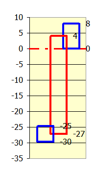
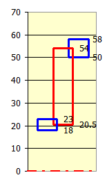
The dimensions can be checked in the picture on the right.
The zero axis defines the nominal dimension D from which the tolerances are
determined.
Blue... Tolerance field of shaft and bearing.
Red... Nominal bearing clearance
Dimensions in [μm] or [10ˉ³in]
By selecting the degree of accuracy, you choose the range of minimum and
maximum bearing clearance and thus the complexity of production. When the button
is checked, the degree of accuracy is selected automatically depending on the
diameter D and ψ'. Generally, the accuracy for the bearing is chosen to be one
degree lower than for the shaft.
For example: Bearing...7, Shaft...6
The dimensions can be checked in the picture on the right.
The zero axis defines the nominal dimension D from which the tolerances are
determined.
Blue... Tolerance field of shaft and bearing.
Red... Nominal bearing clearance
Dimensions in [μm] or [10ˉ³in]
The drop-down list contains a list of ISO 286 fits. The list is sorted by ψ’
value. You can thus simply choose the fit that is closest to the desired ψ’
[2.53].
After selecting the fit, the corresponding bearing and shaft dimensions and
bearing clearance values are recalculated below.
If the button on the right is checked, the tolerance fields are displayed
according to the selected accuracy level and the ISO 286 D diameter (see [2.54,
2.55]).
After unchecking the button, one can select the own values.
The dimensions can be checked in the picture on the right.
The zero axis defines the nominal dimension D from which the tolerances are
determined.
Blue... Tolerance field of shaft and bearing.
Red... Nominal bearing clearance
Dimensions in [μm] or [10ˉ³in]
See the picture for the dimensions of bearing, shaft, bearing clearance.

If it is needed to enter the values of bearing diameter Dmin, Dmax and shaft
diameter DJmin, Djmax directly press the ‘►D.. ’ button.
Switch to paragraph [8.0] where you can enter each exact value.
By unchecking the button on the right the Dmin value can be changed; the
other values of Dmax, DJmin and DJmax will be calculated based on the previous
values, namely:
Dmax = Dmin + (ES-EI)
DJmin = (Dmin + Dmax) / 2 - C - (es-ei)
DJmax = DJmin + (es-ei)
In this section, define the bearing parameters in detail.
When calculating the heating of a bearing that is cooled by convection, it is
necessary to determine the area ‘A’, which is radiating heat.
If the surface area is not known, select the method of the bearing fit from the
list. The next line gives an estimate of the area of "A".
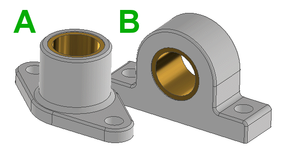
Depending on the dimensions of the bearing and the previous selection, the size of the cooling surface is estimated. After unchecking the button, it is possible to enter a custom value.
To calculate the bearing heating it is necessary to estimate the heat
transfer coefficient.
For still air kA = 12 [W/m²/°K]
Air swirled by rotating shaft only kA = 15-20
For higher air speeds (e.g. fan on shaft), select from the air speed table.
After unchecking the button, one can enter the own value.
You can select Ω=360° for the standard bearings.
For bearing housings with a wiper ring or split bearings, select the appropriate
value.
Follow the picture.
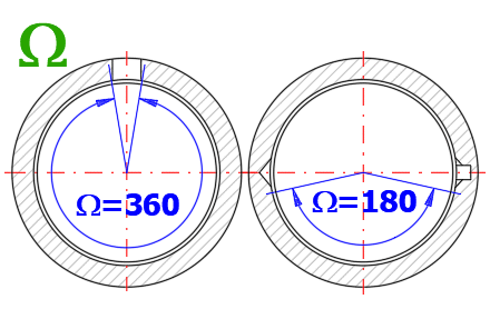
In order to determine the coefficient of friction (and thus the bearing heating), it is necessary to specify whether friction in the unloaded part of the bearing will also be taken into account.
For standard bearings, select Yes.
The selection of the type and dimensions of the bore or lubrication groove
affects the lubricant flow parameter ‘Q3*’ due to the hydrodynamic pressure
‘pen’ (and thus the temperature of the outlet oil).
Select the type from the picture, define the dimensions below.
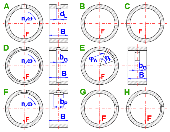
The green box shows the recommended minimum value (ISO3547-3). After
unchecking the button, one can enter the own value.
If the bearing contains lubrication grooves or lubrication pockets, enter their
dimensions according to the picture on the right.
The lubricant supply pressure ‘pen’ should be significantly lower than the specific load of the bearing to avoid additional hydrostatic load. It usually ranges between 0.05 MPa and 0.2 MPa. The depth of the lubrication grooves and lubrication pockets is significantly greater than the bearing clearance.
plim is defined by the selection of friction material at [2.14].
Select a method to determine hlim.
1. Table: In ISO 7902-3 (DIN 31652-3), empirical permissible hlim values are
given for which Rz<4 [μm] for the shaft, small geometric errors of the sliding
surfaces, careful assembly and adequate lubricant filtration are assumed.
2. Calculation (Calc): hlim is defined in detail in the auxiliary calculations
[7.0] and the hlim value from this calculation is used.
3. User: Choosing your own value.
The maximum permissible bearing temperature depends on the bearing material
and lubricant. As the temperature increases, the hardness and strength of the
bearing material (lead and tin alloys due to their low melting points) decreases
and the viscosity of the lubricant decreases. In addition, mineral oil-based
lubricants age at temperatures above 80°C.
For these general empirical values, it is taken into account that the maximum
value of the temperature field is higher than the calculated bearing temperature
or the calculated lubricant outlet temperature.
For pressure lubrication, if the ratio of total lubricant volume to lubricant
volume per minute (lubricant flow) is higher than 5, the temperature may be 10°C
higher.
Values in brackets may be allowed in exceptional cases under special operating
conditions.
Small and medium sliding speeds are v = 1 - 15 [m/s] (3 - 50 [ft/s]).
Commonly, speeds up to 60 - 80 [m/s] (200-260 [ft/s]) are achieved. Special
bearings up to 100 [m/s] (330 [ft/s]).
Friction materials based on rubber, hardened fabric or plastic may have a
limited maximum speed.
Approximate speed at which the fluid friction changes to limiting friction.
An approximate value of high speeds at which turbulent lubricant flow can occur in the bearing, increasing losses and heat development.
Approximate value of the maximum load at which the liquid friction becomes the limited friction.
There are 2 calculations for when the bearing is:
- Cooled by convection
- Pressure oil cooled
In both cases, functional parameters (effective bearing clearance, oil film thickness, friction, heat output) are calculated based on the initial temperature and bearing input parameters (load, dimensions, operating conditions....). When calculating, it is necessary to use an iteration where the estimated initial temperature is gradually refined by the result of the calculation.
Parameters that are outside the recommended values (green cell) are marked
with red text.
The influence of input parameters on the functional parameters of the bearing is
given in the help.
During production, variations in diameters occur within specified tolerances. Thus, during assembly, a shaft with the maximum permissible diameter can be found with a bearing with the minimum permissible diameter Cmin and (or vice versa Cmax). It is therefore advisable to check these extreme options in the calculation.
Select the value of bearing clearance C to be used in the selection list.
A. Convection cooling
B. Oil pressure cooling
The Reynolds number is used to check whether the flow is laminar. If Re is greater than the value in the green cell, the calculation values are not valid and the bearing parameters must be changed.
Effect of input parameters
▲Viscosity .....
=> ▼Re, ▼So, ▼ε, ▲▼hmin, ▲T
▲Clearence ... => ▲Re, ▲So, ▲ε, ▲▼hmin, ▼T
▲Diameter ....
=> ▲Re, ▲So, ▼▲ε, ▲hmin, ▲T
▲Width .........
=> ▼▲Re, ▼So, ▼ε, ▲hmin, ▼T
The recommended minimum viscosity is indicated in the green cell.
The optimal viscosity is then 2-3 times higher.
For slow-running, heavily or shock-loaded bearings, the recommended value is 5-6
times higher.
If the degrees of expansion of the shaft and bearing material are different, the bearing clearance changes with the temperature change.
If the bearing is pressed into the bearing housing (and is not further machined after pressing), the inner diameter of the bearing changes (see lines [2.42-2.46]).
Characteristic parameter for load capacity.
1 < So < 15 ... the bearing operates in the liquid friction range, the running
is stable in standard design and under normal operating conditions.
So < 1 ... due to low specific pressure at high sliding speed there is a risk of
uneven running. It is necessary to change the dynamic viscosity or the B/D
ratio.
So > 15 ... danger of contact between sliding surfaces.
Effect of input parameters
▲Viscosity .....
=> ▼Re, ▼So, ▼ε, ▲▼hmin, ▲T
▲Clearence ... => ▲Re, ▲So, ▲ε, ▲▼hmin, ▼T
▲Diameter ....
=> ▲Re, ▲So, ▼▲ε, ▲hmin, ▲T
▲Width .........
=> ▼▲Re, ▼So, ▼ε, ▲hmin, ▼T
ε < 0.70 ... leads to unsteady operation due to self-excited oscillations
ε > 0.96 ... leads to boundary friction between the peaks of surface roughness
Larger ε values are found in larger bearing diameters with good surface quality.
Effect of input parameters
▲Viscosity .....
=> ▼Re, ▼So, ▼ε, ▲▼hmin, ▲T
▲Clearence ... => ▲Re, ▲So, ▲ε, ▲▼hmin, ▼T
▲Diameter ....
=> ▲Re, ▲So, ▼▲ε, ▲hmin, ▲T
▲Width .........
=> ▼▲Re, ▼So, ▼ε, ▲hmin, ▼T
If the minimum oil film ‘hmin’ thickness is less than the required ‘hlim’ value (green cell)
- You can check the required hlim using the calculation [7.0]
- Adjust bearing parameters
- Reduce bearing temperature by better cooling (area, ventilation)
Effect of input parameters
▲Viscosity .....
=> ▼Re, ▼So, ▼ε, ▲▼hmin, ▲T
▲Clearence ... => ▲Re, ▲So, ▲ε, ▲▼hmin, ▼T
▲Diameter ....
=> ▲Re, ▲So, ▼▲ε, ▲hmin, ▲T
▲Width .........
=> ▼▲Re, ▼So, ▼ε, ▲hmin, ▼T
The green cell indicates whether the following is used:
L + U - specific friction coefficient with respect to the unloaded area of the
lubricating film ‘f '/ψeff’
L Only - specific friction coefficient in the loaded area of the lubricating
film ‘f/ψeff’
Setting on line [2.69]
In addition to the functional parameters of the bearing, the calculation also results in the amount of thermal energy (friction) and, due to the ambient temperature and cooling surface, the end temperature of the bearing TB,1. If it is different from the initial estimate of TB,0, a new estimate of TB,2 must be made and added to TB,0. This iteration must be repeated until the difference between TB,0 and TB,1 is minimum (<1°C).
For one step of this iteration, use the button on the following line "▲TB,0".
For multiple steps in a row, use the button "30x TB,2 ►TB,0 + 30x Tex,2 ►Tex,0".
If the temperature TB,1 exceeds the allowed Tlim temperature (green cell) you
can:
- increase the heat dissipating surface
- increase the air flow rate (ventilation)
- use pressure lubrication.
In addition to the functional parameters of the bearing, the calculation also
results in the amount of thermal energy (friction). The lubricant outlet
temperature Tex,1 is determined from the lubricant inlet temperature Ten and the
lubricant flow rate Q.
If it is different from the initial estimate of Tex,0, a new estimate of Tex,2
must be made and added to Tex,0. This iteration must be repeated until the
difference between Tex,0 and Tex,1 is minimum (<1°C).
For one step of this iteration, use the button on the following line "▲Tex,0".
For multiple steps in a row, use the button "30x TB,2 ►TB,0 + 30x Tex,2 ►Tex,0".
If the temperature Tex,1 exceeds the allowed Tlim temperature (green cell)
you can:
- increase lubricant flow by reducing viscosity
- increase lubricant flow by increasing bearing clearance
Dynamic viscosity of lubricant acc. to ISO and defined lubricant curve (blue).
After entering the temperature Tx, you will find the lubricant parameters for the specified temperature.
Information table of bearing diameters and widths.
mm (SI) …...…. ISO 3547-1, Table 2
in (Imperial) ... Compilation of data from major manufacturers
For easier optimization or search for a functional solution, it is possible to create a graph of the monitored values depending on the specific bearing clearance ψ'.
When the button is pressed, the monitored parameters for the range ψ'<0.0003 - 0.0095> are calculated sequentially.
Select the parameter required to display from the list.
For easy optimization, you can change the most important bearing input parameters at the click of a button. Immediately after the change, the iteration is executed and you can see the change in results on the left.
Use the ▼▲ buttons to change the parameters and the ► button to restart the Automatic design.
Effect of input parameters
▲Viscosity .....
=> ▼Re, ▼So, ▼ε, ▲▼hmin, ▲T
▲Clearence ... => ▲Re, ▲So, ▲ε, ▲▼hmin, ▼T
▲Diameter ....
=> ▲Re, ▲So, ▼▲ε, ▲hmin, ▲T
▲Width .........
=> ▼▲Re, ▼So, ▼ε, ▲hmin, ▼T
For any mechanism where friction occurs, one of the most important issues is the choice of the appropriate lubricant. In this paragraph you can:
A...Select an oil from a table of commonly used oils
B...Select an oil according to ISO3448
C...Define the oil properties
At the same time, you can easily compare the properties of different oils for various temperatures.
Select the desired oil from the table. It is shown in purple in the graph.
After pressing the button on the right, the definition values of the selected
oil are moved to C.
Here you can select the oil based on ISO3448. It is shown in green in the graph. Select gradually:
- Viscosity grade ISO VG 2 - ISO VG 3200
Defines the kinematic viscosity for 40°C v [mm²/s]
- Viscosity index VI=0, VI=50, VI=95
Defines the rate of change in oil viscosity due to temperature change. This
means that a lubricant with a higher viscosity index is desirable because it
provides a more stable lubricating film over a wider temperature range.
- Position in range 0-1
The viscosity grade allows a certain range of kinematic viscosity. For example,
ISOVG100 can have a range between 90-110 [mm²/s]. The VR coefficient defines the
position in this range. The value of 0.5 is therefore in the middle.
After pressing the button on the right, the definition values of the selected oil are moved to C.
Detailed definition of oil properties. It is shown in blue in the graph.
If the supplier defines the oil parameters directly, enter them here.
- Enter the oil density and the temperature for which it is defined.
- Enter the coefficient of thermal expansion.
- Enter a known kinematic or dynamic viscosity for two temperatures T1, T2.
Kinematic or dynamic viscosity inputs are switched via the switches on the right.
The expansion coefficient affects the density for temperatures other than 20°C and is usually ~0.75 for mineral oils.
In the green cell is the value estimated based on the density according to
the table:
Rho [kg/m³]
βL
800 ………...….. 0.77 - 0.85
850 ………...….. 0.72 - 0.84
900 ………...….. 0.63 - 0.81
950 ………...….. 0.50 - 0.77
The viscosity index is determined according to ISO2909. It is determined from the kinematic viscosity for 40°C and 100°C.
If you need to transfer the oil parameters to the calculation in paragraph [2.0], press the button.
The table shows the values for lubricants (A), (B), (C).
The origin of the table (graph) can be set in the Ts cell.
After entering the temperature Tx, you will find the lubricant parameters for the specified temperature.
Roughness comparison tables.
This paragraph can be used to choose a fit and determine tolerances and deviations of machine parts according to the standard ISO 286 (ANSI B4.1) and ISO 12129.
ISO 286: is identical with the European standard EN 20286:1993 and defines an internationally recognized system of tolerances, deviations and fits. The standard ISO 286 is used as an international standard for linear dimension tolerances and has been accepted in most industrially developed countries in identical or modified wording as a national standard (JIS B 0401, DIN ISO 286, BS EN 20286, CSN EN 20286, etc.).
Select the tolerance range of the hole (marked A-ZC, see picture for position) and the accuracy level (numbers 1-18). The deviations with respect to the nominal dimension ‘D’ are immediately calculated and displayed in a graph on the right.
Select the tolerance range of the shaft (marked a-zc, see picture for position) and the accuracy level (numbers 1-18). The deviations with respect to the nominal dimension ‘D’ are immediately calculated and displayed in a graph on the right.
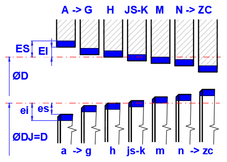
After selecting the tolerance, the values used in the bearing design are calculated.
ISO 12129: standard has been established because it is not possible to use the ISO deviations given in ISO 286-1 and ISO 286-2 to develop clearance fits which correspond to the requirements of plain bearing engineering for approximately uniform mean relative bearing clearances for all nominal size ranges.
The ISO 12129 standard defines bore and shaft deviations for the selected ‘Relative bearing clearance’ ψ' and ‘Nominal diameter’ D.
After selecting the relative bearing clearance from the list, the relevant tolerances and corresponding dimensions are immediately calculated, see the picture and graph on the right.
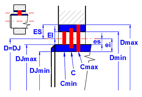
Although there can be
generally coupled parts without any tolerance zones, only two methods of
coupling of holes and shafts are recommended due to constructional,
technological and economic reasons.
A) Hole basis system
The desired clearances and interferences in the fit are achieved by combinations
of various shaft tolerance zones with the hole tolerance zone "H". In this
system of tolerances and fits, the lower deviation of the hole is always equal
to zero.
B) Shaft basis system
The desired clearances and interferences in the fit are achieved by combinations
of various hole tolerance zones with the shaft tolerance zone "h". In this
system of tolerances and fits, the upper deviation of the hole is always equal
to zero.
Depending on the mutual position of tolerance zones of the coupled parts, 3
types of fit can be distinguished:
A) Clearance fit
It is a fit that always enables a clearance between the hole and shaft in the
coupling. The lower limit size of the hole is greater or at least equal to the
upper limit size of the shaft.
B) Transition fit
It is a fit where (depending on the actual sizes of the hole and shaft) both
clearance and interference may occur in the coupling. Tolerance zones of the
hole and shaft partly or completely interfere.
C) Interference fit
It is a fit always ensuring some interference between the hole and shaft in the
coupling. The upper limit size of the hole is smaller or at least equal to the
lower limit size of the shaft.
On the next line is a list of fits, the preferred fits are marked with an
asterisk.
| Clearence fit | Transition fit | Interference fit | |
| H5/g4 | H8/h8 | H5/js4 | H6/n5 |
| H5/h4 | H8/h9 | H5/k4 | H6/p5 |
| H6/f5 | H9/c9 | H5/m4 | H6/r5 |
| H6/g5 | H9/d9 * | H6/js5 | H6/s5 |
| H6/h5 | H9/e8 | H6/j5 | H6/t5 |
| H7/c8 | H9/e9 * | H6/k5 | H6/u5 |
| H7/d8 | H9/f8 | H6/m5 | H7/p6 * |
| H7/e7 | H9/f9 | H7/js6 | H7/r6 * |
| H7/e8 | H9/h8 | H7/j6 * | H7/s6 * |
| H7/f7 * | H9/h9 | H7/k6 * | H7/s7 |
| H7/g6 * | H10/d10 | H7/m6 | H7/t6 |
| H7/h6 * | H10/h9 | H7/n6 * | H7/u6 |
| H8/c8 | H10/h10 | H8/js7 | H7/u7 |
| H8/d8 | H11/a11 | H8/j7 | H8/s7 |
| H8/d9 | H11/b11 | H8/k7 | H8/t7 |
| H8/e8 * | H11/c11 * | H8/m7 | H8/u7 |
| H8/e9 | H11/d9 | H8/n7 | H8/u8 |
| H8/f7 * | H11/d11 | H8/p7 | H8/x8 |
| H8/f8 | H11/h9 | H8/r7 | H8/z8 |
| H8/f9 | H11/h11 | ||
| H8/g7 | H12/b12 | ||
| H8/h7 | H12/h12 | ||
| Clearence fit | Transition fit | Interference fit | |
| G5/h4 | H8/h8 | JS5/h4 | N6/h5 |
| H5/h4 | H9/h8 | K5/h4 | P7/h6 * |
| F7/h5 | D9/h9 | M5/h4 | R7/h6 |
| G6/h5 | D10/h9 * | JS6/h5 | S7/h6 * |
| H6/h5 | E9/h9 * | J6/h5 | T7/h6 |
| D8/h6 | F8/h9 | K6/h5 | U7/h6 |
| E8/h6 | F9/h9 | M6/h5 | U8/h7 |
| F7/h6 | H8/h9 | JS7/h6 | |
| F8/h6 * | H9/h9 | J7/h6 | |
| G7/h6 * | H10/h9 | K7/h6 * | |
| H7/h6 * | H11/h9 | M7/h6 | |
| D8/h7 | D10/h10 | N7/h6 * | |
| E8/h7 | H10/h10 | JS8/h7 | |
| F8/h7 | A11/h11 | J8/h7 | |
| H8/h7 | B11/h11 | K8/h7 | |
| D8/h8 | C11/h11 * | M8/h7 | |
| D9/h8 | D11/h11 | N8/h7 | |
| E8/h8 | H11/h11 | ||
| E9/h8 | B12/h12 | ||
| F8/h8 | H12/h12 | ||
| F9/h8 | |||
| Running or sliding fits [RC] |
| RC 1 (H5/g4) |
| RC 2 (H6/g5) |
| RC 3 (H7/f6) |
| RC 4 (H8/f7) |
| RC 5 (H8/e7) |
| RC 6 (H9/e8) |
| RC 7 (H9/d8) |
| RC 8 (H10/c9) |
| RC 9 (H11/X) |
| Locational clearance fits [LC] |
| LC 1 (H6/h5) |
| LC 2 (H7/h6) |
| LC 3 (H8/h7) |
| LC 4 (H10/h9) |
| LC 5 (H7/g6) |
| LC 6 (H9/f8) |
| LC 7 (H10/e9) |
| LC 8 (H10/d9) |
| LC 9 (H11/c10) |
| LC 10 (H12/X) |
| LC 11 (H13/X) |
| Locational transition fits [LT] |
| LT 1 (H7/js6) |
| LT 2 (H8/js7) |
| LT 3 (H7/k6) |
| LT 4 (H8/k7) |
| LT 5 (H7/n6) |
| LT 6 (H7/n7) |
| Locational interference fits [LN] |
| LN 1 (H6/n5) |
| LN 2 (H7/p6) |
| LN 3 (H7/r6) |
| Force or shrink fits [FN] |
| FN 1 (H6/X) |
| FN 2 (H7/s6) |
| FN 3 (H7/t6) |
| FN 4 (H7/u6) |
| FN 5 (H8/x7) |
| Running or sliding fits [RC] |
| RC 1S (G5/h4) |
| RC 2S (G6/h5) |
| RC 3S (F7/h6) |
| RC 4S (F8/h7) |
| RC 5S (E8/h7) |
| RC 6S (E9/h8) |
| RC 7S (D9/h8) |
| RC 8S (C10/h9) |
| RC 9S (X/X) |
| Locational clearance fits [LC] |
| LC 1S (H6/h5) |
| LC 2S (H7/h6) |
| LC 3S (H8/h7) |
| LC 4S (H10/h9) |
| LC 5S (G7/h6) |
| LC 6S (F9/h8) |
| LC 7S (E10/h9) |
| LC 8S (D10/h9) |
| LC 9S (C11/h10) |
| LC 10S (X/X) |
| LC 11S (X/X) |
| Locational transition fits [LT] |
| LT 1S (X/h6) |
| LT 2S (X/h7) |
| LT 3S (X/h6) |
| LT 4S (X/h7) |
| LT 5S (X/h6) |
| LT 6S (X/h7) |
| Locational interference fits [LN] |
| LN 1S (X/h5) |
| LN 2S (X/h6) |
| LN 3S (X/h6) |
| Force or shrink fits [FN] |
| FN 1S (X/X) |
| FN 2S (X/h6) |
| FN 3S (X/h6) |
| FN 4S (X/h6) |
| FN 5S (X/h7) |
Graphs of maximum values for different speeds.
Select the bearing friction layer material in the selection list. The graph on the right shows the plim versus ‘v’.
For the specified speed, the plim values are read from the graphs.
The value v from paragraph [2.0] is set. After unchecking the button, one can enter the own v value.
Calculation of hlim

The hlim calculation uses the values of D and B from paragraph [2.0].
In cases where there may be limiting friction (frequent running, high pressures and low speeds, rocking motion, insufficient lubrication), the roughness should be kept to a minimum.
Roughness is generally chosen
Bearing: Ra 0.4-1.6 (Rz 1.6-6.3) [μm]
Shaft: Ra 0.2-0.4 (Rz 0.8-1.6) [μm]
The green boxes contain recommended and estimated values based on:
- diameter D
- width B
- level of accuracy, production, rigidity [2.8]
After unchecking the button, one can enter the own values.
The quality of oil filtration is also included in the hlim calculation (in addition to the ISO and DIN standards). Commonly manufactured industrial filters achieve filtration fineness of up to 1 [μm]. Automotive filters achieve 5 [μm].
Specify the minimum particle size that will pass through the filter.
If 0 is entered, the effect is not included.
How the rotation "γ" or the deflection of the shaft in the bearing "yd" can be determined quite accurately in the shaft calculation.
For slewing bearings it is equal to 0.
Calculation of the relative bearing clearance and tolerance fields from precisely specified min/max bearing and shaft diameters.
The nominal diameter D [2.36] from paragraph [2.0] is preset.
After unchecking the button, one can enter the own value.
The diameter D is necessary to calculate the relative bearing clearance ψ'.
Enter the min/max dimensions of the bearing and shaft.
The "◄ =D" button prefills the averages with the D value.
After pressing the "▲[2.0]" button, the following settings will be made:
- ψ' [2.53]
- ES-EI, es-ei [2.56]
- Dmin [2.58]
in paragraph [2.0], so that the entered averages Dmin, Dmax, Djmin, Djmax would correspond.
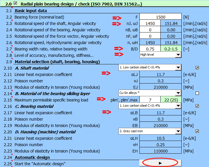
A basic task for which we know the load, material parameters and we want to find a functional (optimal bearing).
Nominal load F=1500 N
Rotational speed of the shaft nJ=1450 /min
Bearing width ratio, relative bearing width B/D ~ 0.75
Shaft and bearing material=Steel (αLJ = 11.7 e-6/°K)
Maximum permissible specific bearing load plim=7MPa
Fill in requested input parameters, select the "Level of accuracy, manufacturing, stiffness…" as "High" and press the "Automatic design" button.
In the results we can see that the hmin value is less than the recommended value.
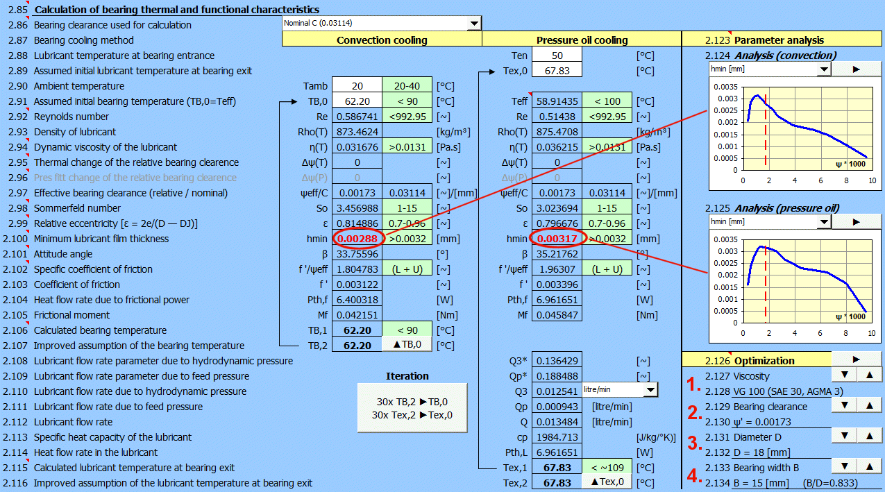
So it is necessary to adjust either the working conditions or the bearing dimensions.
Increase viscosity to VG150 (button "▲"). The hmin value increases and
the bearing is within the permissible operating parameters.
In many cases, however, the viscosity of the lubricant is determined by the
other elements of the machine (common oil management) and a different method
must be chosen for optimisation.
The graphs show that the bearing clearance ψ' is already set so that hmin cannot be increased significantly in this case.
Press the button gradually to increase the diameter. The diameter is changed
according to the standardized series and the bearing width is traced and changed
to maintain the required B/D ratio.
As the bearing gets larger, the lubricant pressure decreases and the minimum oil
film thickness hmin increases.

If changed, the automatic filling of the nominal diameter D is cancelled.

The same applies for changing the bearing width as for changing the diameter. Bearing increase => Lubricant pressure decrease => hmin increase.
The operating temperature of the bearing significantly affects its functional parameters.
A. Convection cooling.
Operating temperature is affected by:
1. Cooling surface (increased A=> decreased temperature => increased hmin).
2. Air flow rate. (increased air velocity => decreased temperature => increased
hmin).
3. Ambient temperature.
The ambient temperature (3.) is usually difficult to change. The cooling
surface A (1.) is estimated according to the size of the bearing body and should
be checked on the basis of the specific design.
The simplest way to do this is to increase the air flow rate, for example by
mounting a fan on the shaft (2.).

Increasing the velocity from 1 m/s (used for natural flow resulting from
shaft rotation) to 5 m/s will reduce the bearing temperature by 10°C and
increase the hmin.
To recalculate the model, press the ‘Iteration’ button.
With pressure oil cooling, the bearing temperature can be controlled by the temperature of the lubricant at the bearing inlet. For example, by increasing the radiator size or the volume of lubricant in the system.

You can try lowering the temperature to 40°C.
To recalculate the model, press the ‘Iteration’ button.
Dimensions: see Example 1
Bearing design is usually based on the relative bearing clearance ‘ψ'’, which determines the nominal bearing clearance ‘C’ (ψ' = C / D). Since it is not possible to manufacture a bearing or shaft with zero tolerance, it is necessary to set the appropriate tolerances for the nominal dimensions. Automatic design sets the selection preferences as follows.
Based on the degree of accuracy (2) and the nominal diameter D, it sets the
tolerance field (4). It also sets Dmin=D (5) and thus Dmax=Dmin+(ES-EI).
Then DJmin and DJmax are calculated based on the relative bearing clearance (1).
This will ensure the bearing tolerance Hx (where Dmin=D [2.36] and x is the degree of precision ITB [2.54]).
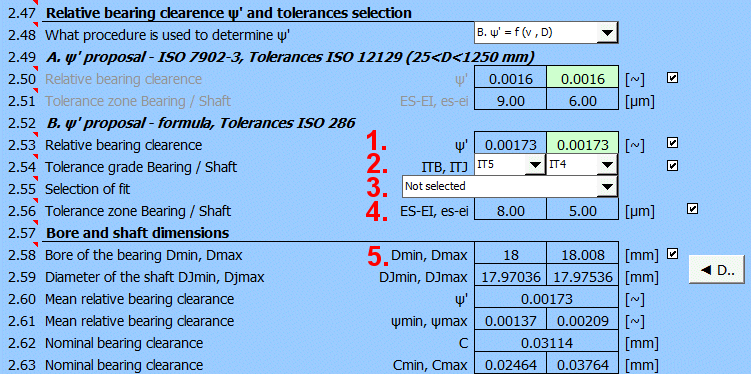
Based on the friction speed, nominal diameter and load, the bearing clearance
ψ' (green cell) is set and used for the calculation.
After unchecking the button, it is possible to enter a custom value
(optimization, materials used,...).
It is set according to the recommendations of ISO12129-1, you can of course choose your own value.
In the selection list (3), the bearing/shaft tolerance combinations according to ISO 286 are sorted by size. Select the one that is the closest to the desired value from line [2.53].
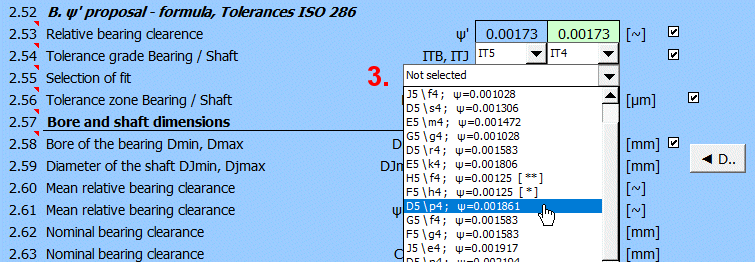
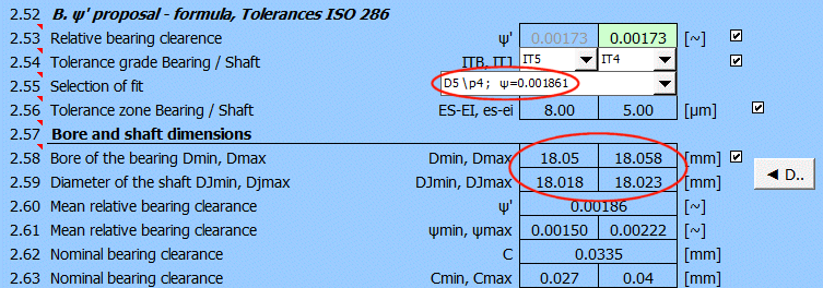
The dimensions Dmin/Dmax and DJmin and DJmax are recalculated to meet the D5\p4 fitting acc. to ISO286 and thus the relative bearing clearance ψ'=0.00186.
Dimensions: see Example 1 + Optimization by changing oil viscosity (VG100 => VG150)
Both the shaft and the bearing are manufactured with a given dimensional tolerance. If no selective assembly is used, it is advisable to check the bearing function also for min/max bearing clearance [2.86].
For the nominal value of bearing clearance, the monitored parameters are within the range of required values (green highlighting).
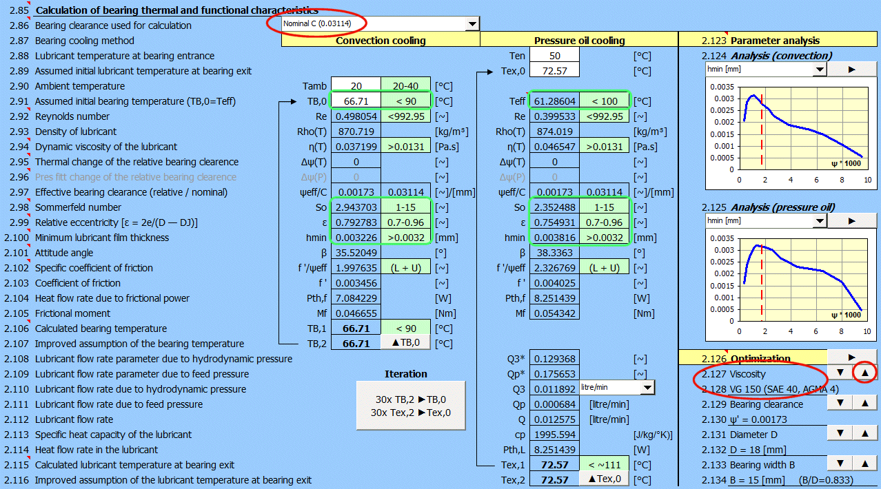
However, if we set the bearing clearance for the combination Dmax (bearing) + DJmin (shaft) => Cmax, the bearing clearance changes and after recalculating the bearing model it is seen that hmin has dropped below the required value.
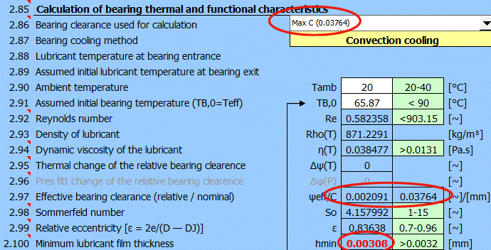
It would probably be necessary to try further optimization (e.g. by changing the oil from VG150 to VG220).
Calculate the heat balance and determine if pressure lubrication with external oil cooling is necessary.
Bearing force (nominal load) F=36000 N .....
[2.2]
Rotational speed of the shaft nJ = 2000 /min ..... [2.3]
Bearing width ratio, relative bearing width B/D=0.5 ..... [2.7]
Shaft linear heat expansion coefficient (steel) αLJ=11 e-6/K .....
[2.11]
Bearing linear heat expansion coefficient (aluminium alloy) αLJ=23 e-6/K
..... [2.17]
Maximum permissible specific bearing load plim'=5 MPa
..... [2.15]
Lubricant selection = ISO VG 100, VI95 ..... [2.27]
Nominal bearing diameter (inside diameter) D=120 mm
..... [2.36]
Mean relative bearing clearance ψ'=0.001 ..... [2.53]
Area of heat-emitting surface (bearing housing) A=0.3 m² .....
[2.66]
Outer heat transmission coeff kA=20 W/m²/K ..... [2.67]
Angular span of bearing segment Ω=360 ° ..... [2.68]
Lubricant hole diameter dL=5 mm ..... [2.71]
Lubricant feed pressure pen=0.5 Mpa ..... [2.73]
Ambient temperature Tamb=40 °C ..... [2.88]
Lubricant temperature at bearing entrance Ten=58 °C ..... [2.87]
Maximum permissible specific bearing load plim'=5 MPa
Maximum permissible bearing temperature Tlim=70 °C
Minimum permissible lubricant film thickness hlim=0.009 mm
< hmin

1) Fill in the "Basic input data" ... [2.2 - 2.23]
2) Press the "Automatic design" button.
3) Enter the values in detail ... [2.27 - 2.78]
4) Enter Tamb=40°C and Ten=58°C ... [2.90, 2.88]
5) Enter 60°C to estimate the temperature TB,0 and Tex,0 ... [2.91, 2.89]
6) Press the "Iteration" button.
Both problems are solved at the same time:
A - Convection cooling
B - Oil pressure cooling
After completion of the iteration (Table1-right), it is clear that the cooling is insufficient and the bearing temperature (TB,0=137.5°C) exceeds the required value of 70°C. There are other values (So, ɛ, hmin) outside the recommendation, so that operation of the bearing would lead to damage.
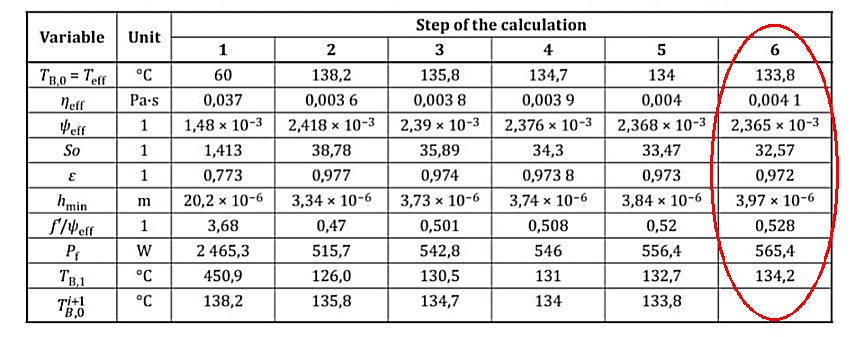
Table 2 gives an example from the ISO standard. The small differences in the results are due to differences in the interpolation of the table values.
Table 1 - Results of iterative calculations for heat dissipation by convection.
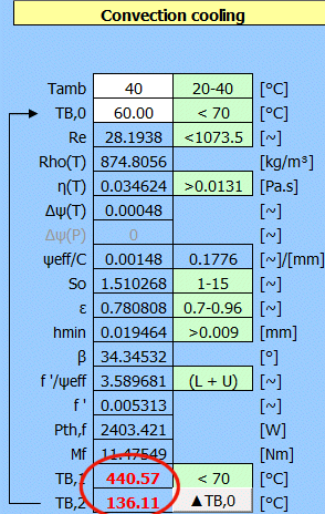
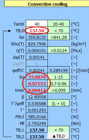
Table 2 - Results of iterative calculations for heat dissipation by convection (ISO example)
In the case of using pressure oil, the operating temperature of the Teff bearing is lower than the required temperature and the parameters So, ɛ, hmin are within the recommended values.
Table 3 – Results of iterative calculation for heat dissipation by lubricant in full bearing
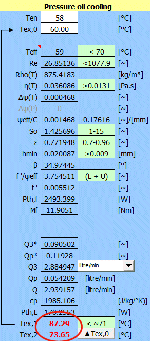
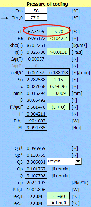
Table 4 - Results of iterative calculation for heat dissipation via the lubricant in full bearing (ISO example)
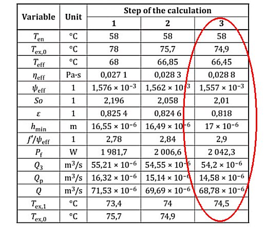
The calculation allows to easily change important input parameters and thus quickly optimize the bearing function.
Use the data from Example 3 and try to reduce the operating temperature of the bearing Teff or the friction dissipated power Pth,f.
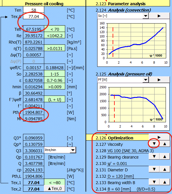
Start from the table of influence of input parameters:
▲Viscosity .....
=> ▼Re, ▼So, ▼ε, ▲▼hmin, ▲T
▲Clearence ... => ▲Re, ▲So, ▲ε, ▲▼hmin, ▼T
▲Diameter ....
=> ▲Re, ▲So, ▼▲ε, ▲hmin, ▲T
▲Width .........
=> ▼▲Re, ▼So, ▼ε, ▲hmin, ▼T
which tell us that as the viscosity of the oil decreases with the temperature. Press the highlighted button three times to get a new result immediately.
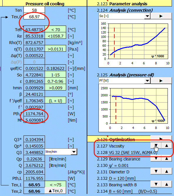
By changing the viscosity of the oil, the losses were reduced by a third and the temperature was reduced by 5°C.
For comparative purposes, we have used the ‘Automatic design’ to design bearings for the combination of the parameters listed below and collated them into 288 clear tables.
A rough, approximate estimate of the bearing size and cooling method can thus be obtained from these tables.
Bearing force (nominal load) F=10N - 500000N [2.2]
Rotational speed of the shaft n=10 - 10000 /min. [2.3]
Bearing width ratio, relative bearing width B/D = 0.4; 0.8; 1.2 [2.7]
Maximum permissible specific bearing load plim=5MPa; 10MPa [2.15]
Level of accuracy, manufacturing, stiffness… Low; High [2.8]
Tables in xls or pdf format: BearingCalcTables.xls or BearingCalcTables.pdf
The name of the sheet is made from: L ... Low, BD0.8 ... B/D=0.8, P5 ... plim=5MPa
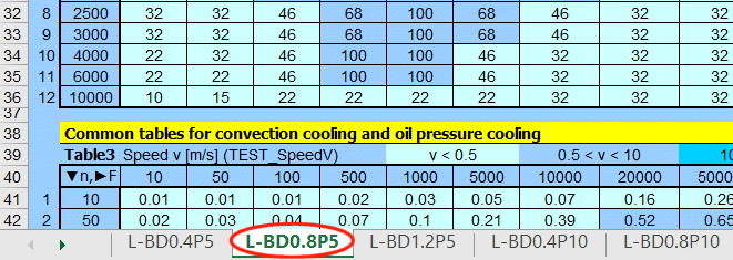
Common tables for convection cooling and oil pressure cooling


............
Different tables for cooling type (A ... Convection cooling, B … Oil pressure cooling)


............
Information on setting of calculation parameters and setting of the language can be found in the document "Setting calculations, change the language".
General information on how to modify and extend calculation workbooks is mentioned in the document "Workbook (calculation) modifications".
Litrature:
[1] Strojně technická příručka (Svatopluk Černoch)
[2] Shigley’s Mechanical Engineering Design
[3] Strojírenská
příručka (1992)
[4]
Machinery’s Handbook
(26th Edition)
[5] Části a mechanismy strojů II
[6] Tribologie (Jan Bečka)
Standards:
ISO 7902:2020
Hydrodynamic plain journal bearings under steady-state conditions Circular
cylindrical bearings
Part1, Part2, Part3
DIN 31652:2017
Gleitlager - Hydrodynamische Radial-Gleitlager im stationären Betrieb
Teil1, Teil2, Teil3
ISO 2909
Viscosity index coefficients
ISO 3448:1992
Table of kinematic viscosity
ISO 3547:2018
Plain bearings Wrapped bushes
Part1, Part2, Part3, Part4
ISO 12129:2019
Plain bearings - Tolerances
Part1, Part2
ISO 4381:2011
Plain bearings - Tin casting alloys for multilayer plain
bearings
ISO 4382:2021
Plain bearings - Copper alloys
ISO 2909
Petroleum products — Calculation of viscosity index from kinematic viscosity
DIN 504
Bearing housings
ISO 3448
Viscosity grades of industrial liquid lubricants
Company catalogues:
SKF, FAG, INA, Timken, RBC Bearings Incorporated, Tecnamic GmbH...
^