The program is intended for design and control of hydrodynamic thrust bearing and plain bearing with tilting pads. The program can solve other problems such as viscosity of lubricants, parameters of friction materials, etc.
The program includes and addresses the following:
1. Design of thrust plain bearing dimensions based on load and operating
conditions
2. Check calculation of various types of bearings
3. Proposal of suitable lubricant, oil database, viscosity calculations
4. Calculation of operating temperatures, coefficient of friction, lubricant
flow and other parameters
5. Database of sliding materials and their parameters
The calculation is based on data, procedures and algorithms from specialized literature, standards and company catalogues.
[1] Strojně technická příručka (Svatopluk Černoch)
[2] Shigley’s Mechanical Engineering Design
[3] Strojírenská
příručka (1992)
[4]
Machinery’s Handbook
(26th Edition)
[5] Části a mechanismy strojů II
[6] Tribologie (Jan Bečka)
Standards: ISO 12130, ISO 12131, DIN 31654, ISO 2909, ISO 3448, ISO 4381, ISO 4382, ISO 2909, ISO 3448
Company catalogues: SKF, FAG, INA, Timken, RBC Bearings Incorporated, Tecnamic GmbH...
User interface.
Download.
Purchase, Price list.
Information on the syntax and control of the calculation can be found in the document "Control, structure and syntax of calculations".
Information on the purpose, use and control of the paragraph "Information on the project" can be found in the document "Information on the project".
The function of the plain bearing is based on the use of fluid friction between the shaft and bearing (or friction segment and pressure plate in the case of thrust bearings). When the shaft and bearing move together, the lubricant is drawn into the narrow gap between the bearing and shaft. This creates a thin film of lubricant that separates the bearing and shaft and causes fluid friction. The creation and maintenance of fluid friction is dependent on numerous parameters. Starting with dimensions, choice of materials, surface quality, choice of lubricant, etc. See figure (f...coefficient of friction, v...sliding speed).
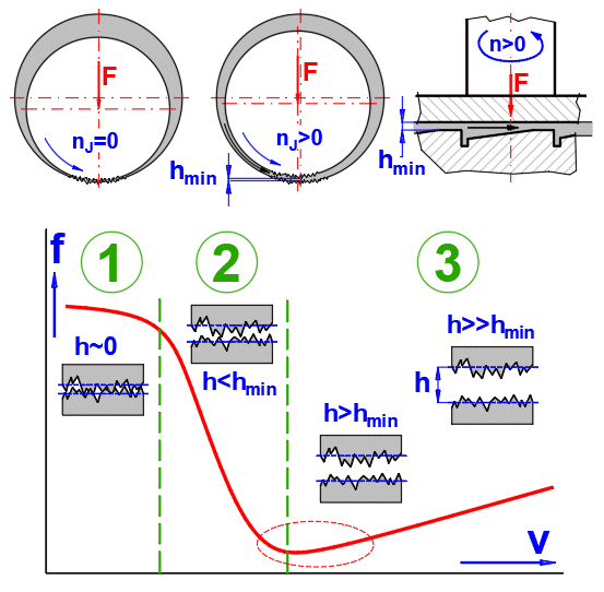
1. Steady state / Dry friction
2. Low speed / Mixed friction
3. High speed / Liquid friction
The calculation is used to control (suggest) whether the bearing, under steady operating conditions, operates in the fluid friction range.
Due to the importance of plain bearings, this issue is addressed in a number of professional publications and standards. The calculation results are comparable for normal use. Therefore, we use the procedures defined by ISO7902 - journal bearings, ISO12131, ISO12130 - plain thrust pad bearings (and related ISO standards) in our calculations. The ISO standard is comparable to DIN31652, DIN 31654..... The calculations are extended with some additional parameters and recommendations based on professional and company literature.
| EN | Table - Symbols and their designations | |
| Symbol | Designation | Unit |
| aF | Distance between supporting point and inlet of the clearance gap in the direction of motion (circumferential direction) | m |
| aF* | Relative distance between supporting point and inlet of the clearance gap in the direction of motion (circumferential direction) | [~] |
| A | Heat-emitting surface of the bearing housing | m² |
| B | Width of one segment | m |
| BL | Segment dimensions ratio BL = B / L | [~] |
| BH | Axial housing width | m |
| Cp | Specific heat capacity of the lubricant (p = constant) | J/kg/°K |
| Cwed | Wedge depth | m |
| D | Mean sliding diameter | m |
| DH | Housing outside diameter | m |
| DR | Diameter ratio (Di / Do) | [~] |
| Di | Inside diameter of friction segments | m |
| Do | Outside diameter of friction segments | m |
| f* | Characteristic value of friction | [~] |
| fB* | Characteristic value of friction for thrust pad bearing | [~] |
| F | Bearing force (load) at nominal rotational frequency | N |
| F* | Characteristic value of load carrying capacity | [~] |
| FB* | Characteristic value of load carrying capacity for thrust pad bearing | [~] |
| Fst | Bearing force (load) at standstill | N |
| h | Local lubricant film thickness (clearance gap height) | m |
| hlim | Minimum permissible lubricant film thickness during operation | m |
| hlim,tr | Minimum permissible lubricant film thickness on transition into mixed lubrication | m |
| hmin | Minimum lubricant film thickness (minimum clearance gap height) | m |
| k | Heat transfer coefficient related to the product B * L * Z | W/m²/°K |
| kA | External heat transfer coefficient (reference surface A) | W/m²/°K |
| L | Length of segment in circumferential direction | m |
| Lwed | Wedge length | m |
| M | Mixing factor | [~] |
| N | Rotational frequency (speed) of thrust collar | /s |
| n | Speed of thrust collar | /min |
| p | Local lubricant film pressure | Pa |
| p' | Specific bearing load p' = F / (B * L * Z) | Pa |
| plim' | Maximum permissible specific bearing load | Pa |
| Pf | Frictional power in the bearing or power generated heat flow rate | W |
| Pth,amb | Heat flow rate to the environment | W |
| Pth,f | Heat flow rate arising from the friction power | W |
| Pth,L | Heat flow rate in the lubricant | W |
| Q | Lubricant flow rate | m³/s |
| Q* | Characteristic value of lubricant flow rate | [~] |
| Q0 | Relative lubricant flow rate Q0 = B * hmin * U * Z | m³/s |
| Q1 | Lubricant flow rate at the inlet of the clearance gap (circumferential direction) | m³/s |
| Q1* | Characteristic value of lubricant flow rate at the inlet of the clearance gap | [~] |
| Q2 | Lubricant flow rate at the outlet of the clearance gap (circumferential direction) | m³/s |
| Q2* | Characteristic value of lubricant flow rate Q1* - Q3* at the outlet of the clearance gap | [~] |
| Q3 | Lubricant flow rate at the sides (perpendicular to circumferential direction) | m³/s |
| Q3* | Characteristic value of lubricant flow rate at the sides | [~] |
| Re | Reynolds’ number | [~] |
| Recr | Critical Reynolds’ number | [~] |
| Rz | Roughness of thrust collar | m |
| Tamb | Ambient temperature | °C |
| TB | Bearing temperature | °C |
| TB,0 | Initial bearing temperature | °C |
| Teff | Effective lubricant film temperature | °C |
| Ten | Lubricant temperature at the inlet of the bearing | °C |
| Tex | Lubricant temperature at the outlet of the bearing | °C |
| Tlim | Maximum permissible bearing temperature | °C |
| T1 | Lubricant temperature at the inlet of the clearance gap | °C |
| T2 | Lubricant temperature at the outlet of the clearance gap | °C |
| U | Sliding velocity relative to mean diameter of bearing ring | m/s |
| wamb | Velocity of air surrounding the bearing housing | m/s |
| Z | Number of segments | [~] |
| β | Angle of one segment | ° |
| η | Dynamic viscosity of the lubricant | Pa.s |
| ηeff | Effective dynamic viscosity of the lubricant | Pa.s |
| Rho | Density of the lubricant | kg/m³ |
| Rho20 | Density of lubricant at 20°C | kg/m³ |
A number of assumptions and simplifications that have been experimentally validated and are listed in the ISO (DIN) standard are used in the calculations. The formulas, relationships and explanations of the calculation deviations from the ISO standard are given here.
The following idealizing
assumptions and preconditions are made, the permissibility of which has been
sufficiently confirmed both experimentally and in practice.
a) The lubricant corresponds to a Newtonian fluid.
b) All lubricant flows are laminar.
c) The lubricant adheres completely to the sliding surfaces.
d) The lubricant is incompressible.
e) The lubricant clearance gap in the loaded area is completely filled with
lubricant. Filling up of the unloaded area depends on the way the lubricant is
supplied to the bearing.
f) Inertia effects, gravitational and magnetic forces of the lubricant are
negligible.
g) The components forming the lubrication clearance gap are rigid or their
deformation is negligible; their surfaces are ideal circular cylinders.
h) The radii of curvature of the surfaces in relative motion are large in
comparison with the lubricant film thicknesses.
I) The lubricant film thickness in the axial direction (z-coordinate) is
constant.
j) Fluctuations in pressure within the lubricant film normal to the bearing
surfaces (y-coordinate) are negligible.
k) There is no motion normal to the bearing surfaces (y-coordinate).
l) The lubricant is isoviscous over the entire lubrication clearance gap.
m) The lubricant is fed in at the start of the bearing liner or where the
lubrication clearance gap is widest; the magnitude of the lubricant feed
pressure is negligible in comparison with the lubricant film pressures.
The calculation solves two cases, namely:
1. Bearing cooling by convection
2. Bearing cooling with pressure oil
Since the problem is not directly solvable, the following successive
iteration was used:
1. The working temperature of the bearing is estimated (or the oil outlet
temperature for cooling with pressure oil)
2. The lubricant parameters are calculated from the temperature
3. Other parameters characterising the bearing function are calculated
4. The power loss (friction) is calculated and thus the working temperature of
the bearing (or the oil outlet temperature for cooling with pressure oil)
5. Based on the temperatures from points 1 and 4, the new working temperature
for point 1 is approximated and the calculation is repeated.
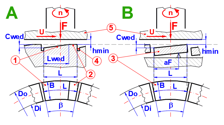
A. Plain thrust pad bearing (ISO 12131)
1. Wedge surface
2. Supporting surface
4. Lubrication groowe
5. Thrust collar
B. Plain tilting pad thrust bearings
(ISO 12130)
3. Tilting-pad
5. Thrust collar
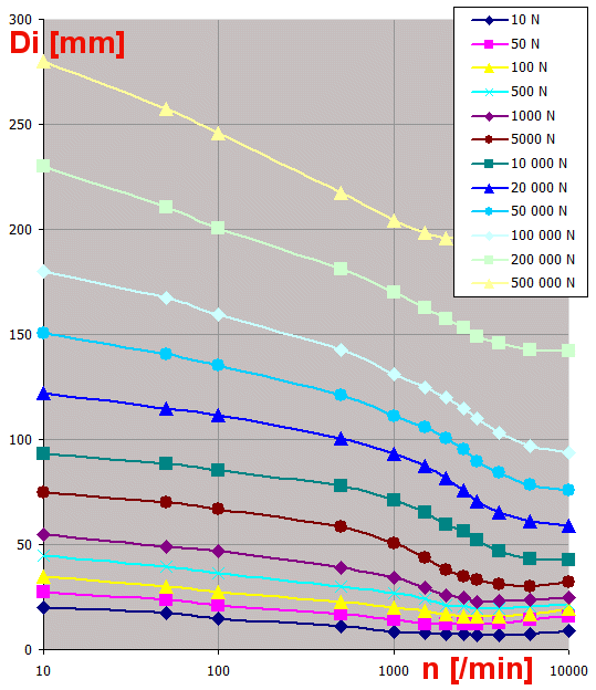
For the design of Di, a graph (load and speed dependence) is used, which is corrected for the Di/Do ratio and plim.
D = (Di + Do) / 2
B = (Do - Di) / 2
Z = 2 * PI() / ((1.08 + 0.03 * U½) * (β * PI() / 180))
For plain bearings with tilting segments, Z is multiplied by 0.9. Z is rounded to the nearest integer.
(checking if the flow is laminar)
Re = (Rho * U * hmin) / ηeff <= 600
Used formula:
Rho = Rho20 / (1 + (Tx - 20°C) * (βL / 1000))
ISO:
He doesn't specify. Requires direct input of the value Rho * cp for the operating temperature of the bearing
DIN:
Rho = Rho20 - (Tx - 20°C) * 0.00064
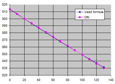
For: Rho20 = 900kg/m³, βL=0.75, X...°C, Y...kg/m³
Used formula:
cp = 4.588 * Tx - 0.005024 * Rho20^2 + 7.115 * Rho20 - 619.646
ISO:
He doesn't specify. Requires direct input of the value Rho * cp for the operating temperature of the bearing
DIN:
Rho * cp = 1.57 + 0.003 * TempC
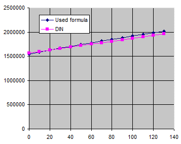
For: Rho20 = 900kg/m³, Beta=0.75, X...°C, Y...J/m³/K
Oil is defined by temperature T1, T2, kinematic viscosity v1, v2, density and by thermal expansion coefficient.
The viscosity is
calculated with use of the formulas in the standard (ASTMD341):
log(log(v + 0.7)) = A - B * log(T) ... [T...Kelvin, v...cSt, A,B ... constants]
B = {log(log(v2 + 0.7)) - log(log(v1+0.7))} / (log(T1)-log(T2))
A = log(log(v2 + 0.7)) + B * log(T2)
v = 10^(10^(A - B * log(T))) - 0.7 ... [v...Kinematic
viscosity]
η = Rho *
v
... [Rho...Density]
Ambient temperature: Tamb
Initial bearing temperature: TB,0
Relative minimum lubricant film thickness: hmin/Cwed (0.8 is used)
F* = (F · hmin²) / (U · ηeff · L² · B · Z)
FB* = F* ·
(Cwed / hmin)²
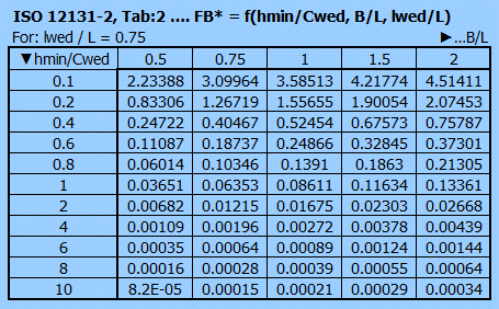
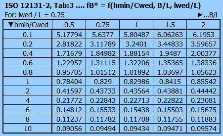
FB* = f (hmin/Cwed; B/L; lwed/L)
From ISO12131-2 Tab2 is from FB*; B/L and lwed/L determined the "hmin/Cwed" => hmin
From ISO12131-2 Tab3 is from hmin/Cwed; B/L and lwed/L determined the fB* value
Heat dissipation by convection. Heat dissipation by convection takes place by thermal conduction in the bearing housing and radiation and convection from the surface of the housing to the environment.
Pth,amb = kA * A * (TB - Tamb)
kA = (15 - 20) W/m²/K [without ventilation]
kA = 7 + 12 * (Va)½ [Va > 0]
Should the area of the heat-emitting surface, A, of the bearing housing not be known exactly, it is possible to use approximate estimates depending on the bearing type mounting.
k = (kA * A) / (B * L * Z)
TB,1 = fB* · (U² · ηeff) / (k · Cwed) + Tamb
TB,0 = 0.5 * (TB,1 + TB,0)
Ambient temperature: Tamb
Lubricant temperature at the inlet of the bearing: Ten
Lubricant temperature at the outlet of the bearing: Tex
Effective lubricant film temperature: Teff,0
Relative minimum lubricant film thickness: hmin/Cwed (0.8 is used)
The calculation of the parameters F*, FB*, hmin/Cwed, hmin, fB* is the same as in the case of convection cooling.
Pf = fB* · (U² · ηeff · B · L · Z) / Cwed
Q0 = B * hmin * U * Z
ΔT = Tex - Ten
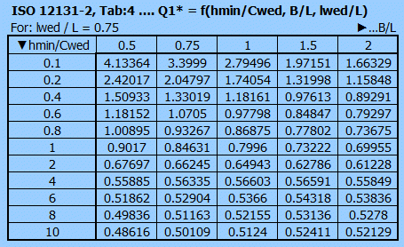
Q = Pf / (cp * Rho * ΔT) = Q* · Q0
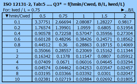
From ISO 12131-2 Tab4, Tab5 is from hmin/Cwed; B/L and lwed/L determined the Q1*, Q3* value
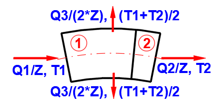
ΔT2 = (ΔT · Q*) / (Q2* + 0.5 · Q3*) = (ΔT · Q*) / (Q1* - 0.5 · Q3*)
ΔT1 = Q2 / (M · Q + (1 - M) · Q3) · ΔT2 = Q2* / (M · Q* + (1 - M) · Q3*) · ΔT2
Teff,1 = Ten + ΔT1 + 0.5 · ΔT2 = Ten + (ΔT* +0.5) · ΔT2
Teff,0 = 0.5 * (Teff,1 + Teff,0)
Pth,L = Rho * Cp * Q * (Tex - Ten)
The calculation can be used in several ways. Indicative, design and control.
Quick indicative determination of bearing size and decision between convection cooling and pressurized oil cooling.
1. Enter the basic input data [2.1-2.9]
2. Select the bearing quality level [2.10]
3. Select/set the parameters of the bearing material [2.6]
4. Press the button for Automatic design [2.12]
5. The Automatic design will attempt to estimate the remaining input parameters
based on the general recommendations
6. On lines [2.48-2.76] the functional parameters can be checked immediately
Overall design with detailed specification of all input parameters.
1. Make an indicative calculation (A)
2. Go through the input parameters [2.13-2.47] and tune the parameters you know
3. Start the temperature iteration with the ‘Iteration’ button [2.72]
4. If any of the functional parameters [2.48-2.76] do not fit, use the
Optimization at the end of the paragraph for a quick change and check.
Functional parameters check.
1. Enter the basic input data [2.1-2.9]
2. Go through the other input parameters [2.13-2.47] and define them
3. Start the temperature iteration with the ‘Iteration’ button [2.72]
In this paragraph you set the units of calculation.
Select the desired system of calculation units in the list box. After switching over the units, all values will be changed immediately.
Type the value you want to convert into the input box on the left. Select source units and target units on the right.
The Ra and Rz roughness parameters are not directly transferable.
However, based on statistical evaluation, it can be said that with a very high probability the roughness Ra(Rz) derived from the roughness Rz(Ra) will lie within the range of values in parentheses. The biggest influence is the chosen machining technology.
The formula Rz=4*Ra is used to convert the entered value
The conversion formula for:
Rz => Ra
Ramin = 0.03 * Rz^1.3
Ramax = 0.24 * Rz^1.06
Ra => Rz
Rzmin = 3.8 * Ra^0.95
Rzmax = 14.5 * Ra^0.75
The paragraph contains a complete design and control calculations.
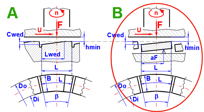
Select the bearing type and enter the basic input data according to the pictures.
Select the bearing type according to the picture.
A. For smaller bearings.
- Uniform pressure distribution is not possible for large bearings.
- The bevel (Cwed, Lwed) is only suitable for one speed
B. For large bearings
- Self-adjusting (tilting) segment
- Optimum friction coefficient
- High specific pressures, high speeds

Usually the load at zero speed is zero (= 0). One can select the load level
as F/Fst ratio from the list on the right.
The first item in the list allows to enter a custom value.
Material groups are mentioned in the list with empirical plim values in parentheses. These values are based on ISO 7902-3,Tab3/ISO 12130-3,Tab3, respecting the requirement for minimum distortion of the sliding surfaces that does not result in deterioration of the bearing operation. The selected value is used on the next line. After unchecking the button, one can enter the own value.
Detailed diagrams can be found in Chapter [5.0].
Materials marked with ‘*’ – ISO recommendation
Unmarked materials – professional literature
The green cell contains two values.
- The first value reflects the sliding velocity ‘v’ from the empirical value in
the list on the previous line (larger plim is possible for small ‘v’ values).
- The second value in brackets indicates the maximum plim value that is
achievable in exceptional cases (very low sliding speeds, precision, structure
rigidity, etc.)
After unchecking the button, one can enter the own value.
The Di/Do ratio is usually chosen in the range of 0.4-0.6. Up to 0.8 for high-speed and special bearings.
The BL ratio is usually selected in the range of 0.8-1.2
The setting affects the determination of the Rz roughness and in some cases
the Diprop design.
In most cases, the ‘Medium level’ is sufficient.
During the automatic design, other calculation parameters are estimated and set based on the load, speed, DR, BL ratio and settings [2.6] and the final iteration is started to solve the bearing operating temperature.
Press the button to start the design proposal.
When choosing a lubricant, there are two options.
A) The proposed bearing uses a common oil management within the machine. The
oil is defined.
B) The lubricant parameters can be modified to best suit the operating
requirements of the bearing.
In general, the higher the RPM, the lower the lubricant VG, and the higher the temperature, the higher the lubricant VG.
Select the appropriate oil and its viscosity index from the list. The parameters are defined by the following 3 lines. If you know the exact parameters of the oil, tick the button on the right and define them. Oils are usually defined by their dynamic viscosity for two temperatures and density at 20°C.
A schematic diagram of standard oils according to ISO 3448 in the range VG10-VG460 is shown on the right and the curve of the defined oil is shown in blue.
VG - Recomendation
| Bearing / Oil Temperature | ||||
| <50°C | 60°C | 75°C | 90°C | |
| n [/min] | <120°F | 140°F | 167°F | 194°F |
| < 300 | 68 | 100 | 220 | --- |
| 300-1500 | 46 | 68 | 100-150 | 150 |
| 1500-3000 | 32 | 32-46 | 68-100 | 100 |
| 3000-6000 | 32 | 32 | 46-68 | 68-100 |
| 6000-10000 | 32 | 32 | 32 | 32-46 |
The expansion coefficient affects the density for temperatures other than 20°C and is usually ~0.75 for mineral oils.
In the green cell is the value estimated based on the density according to
the table:
Rho [kg/m³] BetaL
800 ………...….. 0.77 - 0.85
850 ………...….. 0.72 - 0.84
900 ………...….. 0.63 - 0.81
950 ………...….. 0.50 - 0.77
Define the dimensions of the bearing and bearing pads according to the figure
on the right.
With all buttons [2.23-2.26] checked, the suggested values based on parameters
[2.2-2.10] are used. See the dynamic image on the right.
If you want to set the customised dimensions, uncheck the buttons one by one and
enter your values. The dynamic image is updated with each change.
Dimensions based on the baseline estimate are shown in light black.
Preliminary draft.
The design value of the inner diameter Diprop is approximated from the solution
table Diprop=f(F,n).
This value is then adjusted based on the parameters [2.8-2.10] and a check for
plim is performed [2.6].
After rounding to the table value, the Di value is shown on the next line.

The maximum possible number of segments is given in brackets.
The recommended value is based on the friction speed.
Define the dimensions of the bearing segment according to the figure.
When the button is checked, the recommended values are used.
Cwed: The recommended value is estimated based on the average of D [2.27]
Lwed: The recommended value is 75% of the length of segment L.
aF*: The relative distance (aF*=aF / L) between the fulcrum and the entrance to the gap in the direction of movement (circumferential direction). It has been estimated based on β [2.29] and DR [2.30].
It ranges from 0.55-0.75
If you want to set your own dimensions, check off the buttons one by one and enter your values.
When calculating the heating of a bearing that is cooled by convection, it is
necessary to determine the area "A", which is radiating
heat.
If the surface area is not known, select the method of the bearing fit from the
list. The next line gives an estimate of the area of "A".
Depending on the dimensions of the bearing and the previous selection, the size of the cooling surface is estimated. After unchecking the button, it is possible to enter a custom value.
To calculate the bearing heating it is necessary to estimate the heat
transfer coefficient.
For still air kA = 12 [W/m²/°K]
Air swirled by rotating shaft only kA = 15-20
For higher air speeds (e.g. fan on shaft), select from the air speed table.
After unchecking the button, one can enter the own value.
Minimum permissible lubricant film thickness on transition into mixed lubrication
The maximum permissible bearing temperature depends on the bearing material
and lubricant. As the temperature increases, the hardness and strength of the
bearing material (lead and tin alloys due to their low melting points) decreases
and the viscosity of the lubricant decreases. In addition, mineral oil-based
lubricants age at temperatures above 80°C.
For these general empirical values, it is taken into account that the maximum
value of the temperature field is higher than the calculated bearing temperature
or the calculated lubricant outlet temperature.
For pressure lubrication, if the ratio of total lubricant volume to lubricant
volume per minute (lubricant flow) is higher than 5, the temperature may be 10°C
higher.
Values in brackets may be allowed in exceptional cases under special operating
conditions.
There are 2 calculations for when the bearing is:
- Cooled by convection
- Pressure oil cooled
In both cases, functional parameters (effective bearing clearance, oil film thickness, friction, heat output) are calculated based on the initial temperature and bearing input parameters (load, dimensions, operating conditions....). When calculating, it is necessary to use an iteration where the estimated initial temperature is gradually refined by the result of the calculation.
Parameters that are outside the recommended values (green cell) are marked
with red text.
The influence of input parameters on the functional parameters of the bearing is
given in the help.
According to experience, the value of Tex,0 is selected in the range Ten+10°K to Ten+30°K.
The Reynolds number is used to check whether the flow is laminar. If Re is greater than the value in the green cell, the calculation values are not valid and the bearing parameters must be changed.
The recommended minimum viscosity is indicated in the green cell.
The optimal viscosity is then 2-3 times higher.
For slow-running, heavily or shock-loaded bearings, the recommended value is 5-6
times higher.
The value of hmin/Cwed should be in the range:
0.1-10 ......Thrust plain
bearings (ISO 12131)
0.2-2.0 ......Thrust plain bearings with tilting pads
(ISO 12130)
If the minimum oil film 'hmin' thickness is less than the required 'hlim' value (green cell) you can:
Convection cooling
- Adjust bearing parameters
- Reduce bearing temperature by better cooling (surface, ventilation)
Pressure oil cooling
- Adjust bearing parameters
- Reduce lubricant temperature
Effect of input parameters:
▲Viscosity ........................ => ▼Re, ▲hmin, ▲T
▲Ratio Di / Do .................. => ▼Re, ▼▲hmin, ▼▲T
▲Ratio B / L ..................... => ▼▲Re, ▲hmin, ▼▲T
▲Diameter Di ................... => ▲Re, ▲hmin, ▼▲T
▲Number of segments Z ... => ▲Re, ▲hmin, ▲T
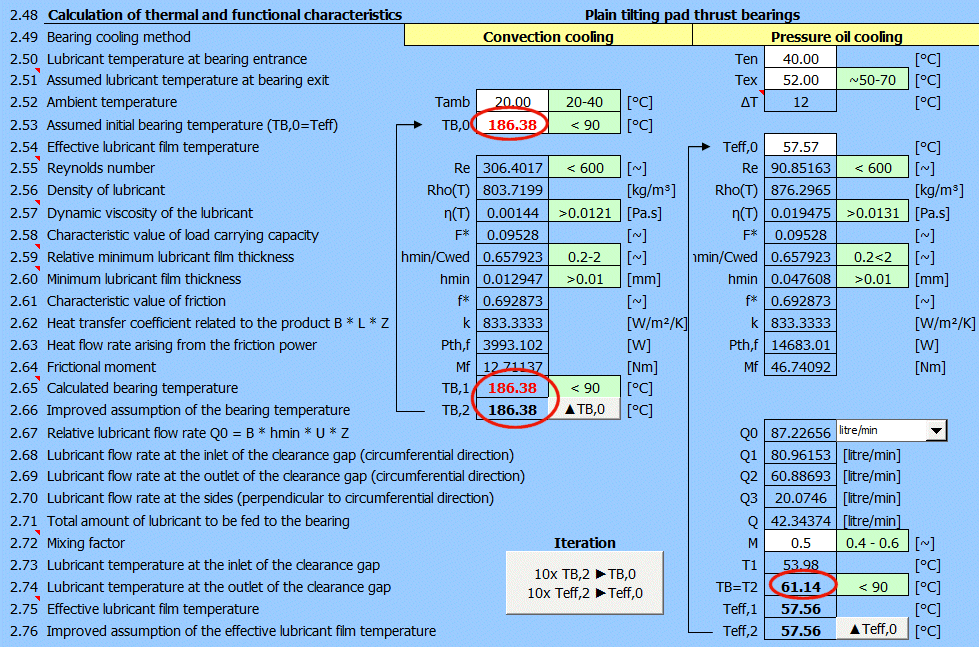
In addition to the functional parameters of the bearing, the calculation also results in the amount of thermal energy (friction) and, due to the ambient temperature and cooling surface, the end temperature of the bearing TB,1. If it is different from the initial estimate of TB,0, a new estimate of TB,2 must be made and added to TB,0. This iteration must be repeated until the difference between TB,0 and TB,1 is minimum (<1°C).
For one step of this iteration, use the button on the following line "▲TB,0".
For multiple steps in a row, use the button "10x TB,2 ►TB,0 + 10x Teff,2 ►Teff,0".
If the temperature TB,1 exceeds the allowed Tlim temperature (green
cell) you can:
- increase the heat dissipating surface
- increase the air flow rate (ventilation)
- use pressure lubrication.
Indicates the level of lubricant mixing in the lubrication groove (4) between the total lubricant inflow Q and the lubricant flow Q2 at the outlet of the friction segment. M=1 means complete mixing of the lubricant. It depends on the bearing design and is used in the range of 0.4-0.6.
The T2 temperature is taken as the TB bearing temperature and must be less than the permissible Tlim value (green cell).
If the temperature T2=TB exceeds the allowed Tlim temperature
(green cell) you can:
- increase lubricant flow by reducing viscosity
- change lubricant inlet/outlet temperature
In addition to the functional parameters of the bearing, the calculation also results in the amount of thermal energy (friction). The lubricant outlet temperature Teff,1 is determined from the lubricant temperature Ten,Tex and the lubricant flow rate Q.
If it is different from the initial estimate of Teff,0,
a new estimate of Teff,2 must be made and added to Teff,0.
This iteration must be repeated until the difference between Teff,0
and Teff,1 is minimum (<1°C).
For one step of this iteration, use the button on the following line "▲Teff,0".
For multiple steps in a row, use the button "10x TB,2
►TB,0 + 10x Teff,2 ►Teff,0".
A. Plain thrust pad bearing
(ISO 12131)
1. Wedge surface
2. Supporting surface
4. Lubrication groowe
5. Thrust collar
B. Plain tilting pad thrust bearings
(ISO 12130)
3. Tilting-pad
5. Thrust collar
Dynamic viscosity of lubricant acc. to ISO and defined lubricant curve (blue).
After entering the temperature Tx, you will find the lubricant parameters for the specified temperature.
A. Plain thrust pad bearing
1. Wedge surface
2. Supporting surface
B. Plain tilting pad thrust bearings
3. Tilting-pad
For easy optimization, you can change the most important bearing
input parameters at the click of a button. Immediately after the change, the
iteration is executed and you can see the change in results on the left.
Use the ▼▲ buttons to change the parameters and the ► button to restart the
Automatic design.
Effect of input parameters:
▲Viscosity ........................ => ▼Re, ▲hmin, ▲T
▲Ratio Di / Do .................. => ▼Re, ▼▲hmin, ▼▲T
▲Ratio B / L ..................... => ▼▲Re, ▲hmin, ▼▲T
▲Diameter Di ................... => ▲Re, ▲hmin, ▼▲T
▲Number of segments Z ... => ▲Re, ▲hmin, ▲T
For any mechanism where friction occurs, one of the most important issues is the choice of the appropriate lubricant. In this paragraph you can:
A...Select an oil from a table of commonly used oils
B...Select an oil according to ISO3448
C...Define the oil properties
At the same time, you can easily compare the properties of different oils for various temperatures.
Select the desired oil from the table. It is shown in purple in the graph.
After pressing the button on the right, the definition values of the selected
oil are moved to C.
Here you can select the oil based on ISO3448. It is shown in green in the graph. Select gradually:
- Viscosity grade ISO VG 2 - ISO VG 3200
Defines the kinematic viscosity for 40°C v [mm²/s]
- Viscosity index VI=0, VI=50, VI=95
Defines the rate of change in oil viscosity due to temperature change. This
means that a lubricant with a higher viscosity index is desirable because it
provides a more stable lubricating film over a wider temperature range.
- Position in range 0-1
The viscosity grade allows a certain range of kinematic viscosity. For example,
ISOVG100 can have a range between 90-110 [mm²/s]. The VR coefficient defines the
position in this range. The value of 0.5 is therefore in the middle.
After pressing the button on the right, the definition values of the selected oil are moved to C.
Detailed definition of oil properties. It is shown in blue in the graph.
If the supplier defines the oil parameters directly, enter them here.
- Enter the oil density and the temperature for which it is defined.
- Enter the coefficient of thermal expansion.
- Enter a known kinematic or dynamic viscosity for two temperatures T1, T2.
Kinematic or dynamic viscosity inputs are switched via the switches on the right.
The expansion coefficient affects the density for temperatures other than 20°C and is usually ~0.75 for mineral oils.
In the green cell is the value estimated based on the density according to
the table:
Rho [kg/m³]
βL
800 ………...….. 0.77 - 0.85
850 ………...….. 0.72 - 0.84
900 ………...….. 0.63 - 0.81
950 ………...….. 0.50 - 0.77
The viscosity index is determined according to ISO2909. It is determined from the kinematic viscosity for 40°C and 100°C.
If you need to transfer the oil parameters to the calculation in paragraph [2.0], press the button.
The table shows the values for lubricants (A), (B), (C).
The origin of the table (graph) can be set in the Ts cell.
After entering the temperature Tx, you will find the lubricant parameters for the specified temperature.
Roughness comparison tables.
Graphs of maximum values for different speeds.
Select the bearing friction layer material in the selection list. The graph on the right shows the plim versus ‘v’.
For the specified speed, the plim values are read from the graphs.
The value v from paragraph [2.0] is set. After unchecking the button, one can
enter the own v value.
A basic task for which we know the bearing type, load, material parameters and we want to find a functional (optimal bearing).
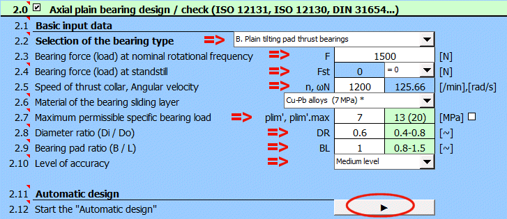
Selection of the bearing type = Plain
tilting pad thrust bearings
Bearing force (load) at nominal rotational frequency F=1500 N
Bearing force (load) at standstill Fst=0 N
Speed of thrust collar n=1200 /min
Maximum permissible specific bearing load plim=7MPa
Diameter ratio (Di / Do) DR=0.6
Bearing pad ratio (B / L) BL=1
Fill in requested input parameters, select the "Level of accuracy " as "High" and press the "Automatic design" button.
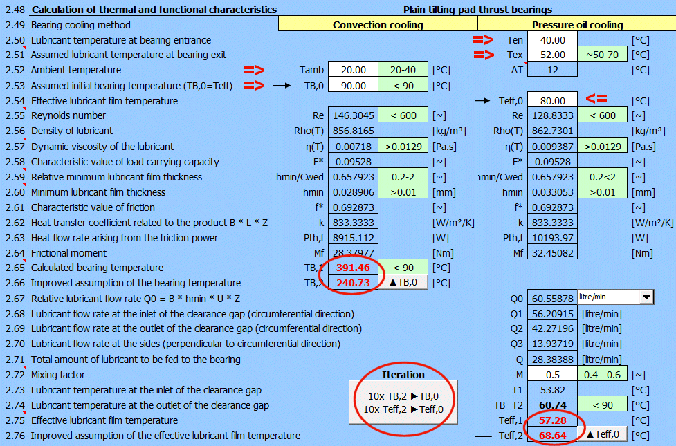
In the results we can see that the allowable bearing temperature for cooling the
bearing by convection is exceeded.
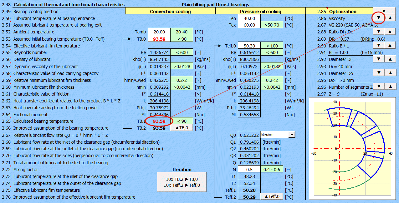
If you do not want / cannot use oil pressure cooling, the temperature can be lowered as follows:
Reduce the viscosity of the lubricant (‘▼’ button). The temperature is reduced and the bearing is operating within the permissible operating parameters.
In many cases, however, the viscosity of the lubricant is determined by the other elements of the machine (common oil management) and a different method must be chosen for optimisation.
If the bearing temperature is close to the maximum permissible temperature, it is advisable to check and, if necessary, increase the bearing surface.

The default value is 1.2 m/s, which corresponds to the air flow caused by the shaft rotation (heat transfer coefficient kA=15-20 W/m²/K). It is possible to increase the speed, for example, by mounting a fan on the shaft.

Bearing B - Plain tilting pad thrust bearing

Calculate the heat balance and determine if the use of circulating pressure lubrication with external oil cooling is necessary.
Detailed bearing specification according to ISO 12130 Table A.3
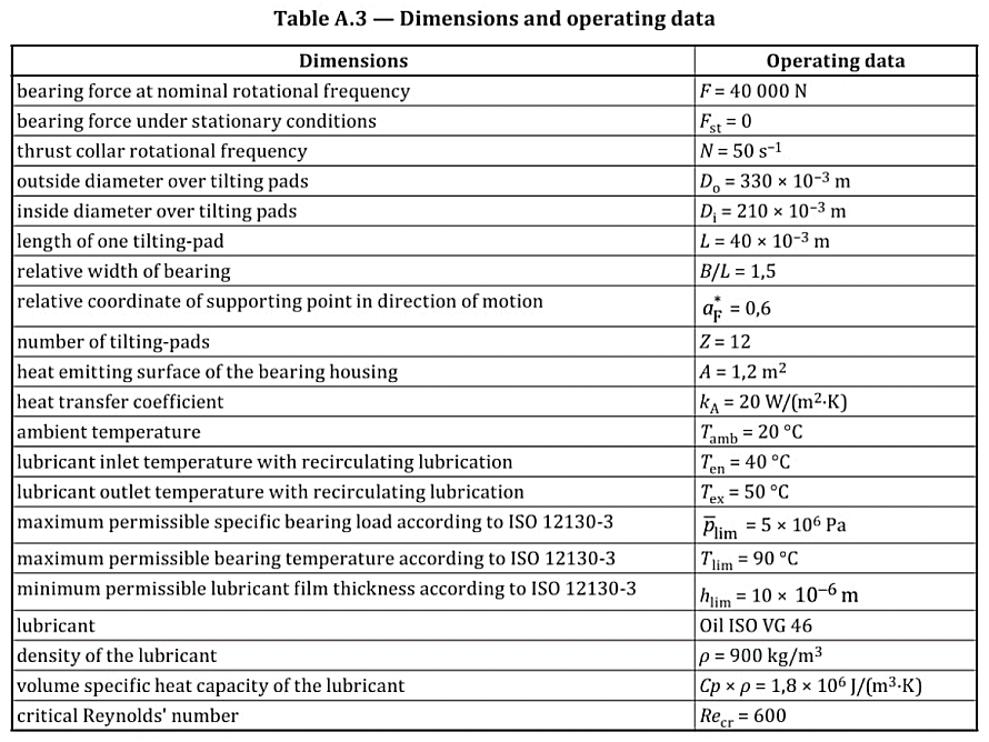
Basic input data
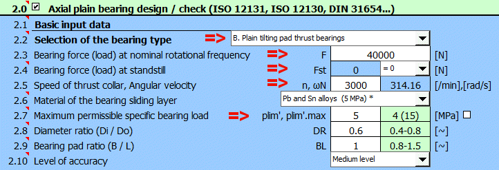
Detailed specification
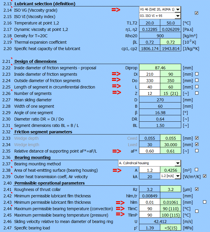
Solution method – results
1) Fill in the desired temperatures (Tamb, Ten, Tex) and estimated
temperatures (TB,0, Teff,0).
It can be seen that the estimated temperatures TB,0 and Teff,0 do not match the
results of the calculation of TB,1 and Teff1. The new estimate is in TB,2 and
Teff,2
2) Press the ‘Iteration’ button.
Only cooling by circulating oil lubrication with pressure lubrication meets the maximum permissible temperature Tlim=90°C.

Information on setting of calculation parameters and setting of the language can be found in the document "Setting calculations, change the language".
General information on how to modify and extend calculation workbooks is mentioned in the document "Workbook (calculation) modifications".
Litrature:
[1] Strojně technická příručka (Svatopluk Černoch)
[2] Shigley’s Mechanical Engineering Design
[3] Strojírenská
příručka (1992)
[4]
Machinery’s Handbook
(26th Edition)
[5] Části a mechanismy strojů II
[6] Tribologie (Jan Bečka)
Standards:
ISO 12130:2021
Plain bearings - Hydrodynamic plain tilting pad thrust bearings under
steady-state conditions
Part1, Part2, Part3
ISO 12131:2020
Plain bearings - Hydrodynamic plain thrust pad bearings under steady-state
conditions
Part1, Part2, Part3
DIN 31654
Hydrodynamische Axial-Gleitlager im stationären Betrieb
Teil1, Teil2, Teil3
ISO 2909
Viscosity index coefficients
ISO 3448:1992
Table of kinematic viscosity
ISO 4381:2011
Plain bearings - Tin casting alloys for multilayer plain
bearings
ISO 4382:2021
Plain bearings - Copper alloys
ISO 2909
Petroleum products — Calculation of viscosity index from kinematic viscosity
ISO 3448
Viscosity grades of industrial liquid lubricants
Company catalogues:
SKF, FAG, INA, Timken, RBC Bearings Incorporated, Tecnamic GmbH...
^