The application is designed for calculations of straight, maximum three times static indefinite beams with constant axis-symmetrical profiles. The programme solves the following tasks:
Simple definition of the type of beam and its loading with visual check.
Calculation of area characteristics of 20 types of cross sections.
Calculation of reactions in supports.
Calculation of minimum / maximum bending moment, stress and deflection of the beam.
Calculation and graphic illustration of the moment, stress, deflection and bending angle of the loaded beam.
The application includes a table of materials and a table of area characteristics of W, S, C, L profiles acc. to ANSI/AISC and I, U, L a T profiles acc. to DIN/ISO.
The calculation is based on data, procedures, algorithms and data from specialized literature and AGMA, ISO, DIN and BS standards.
List of standards (DIN 1025, 1026, 1028, 1029, 1024, AISC W, S, C, L, LU ... )
User interface.
Download.
Purchase, Price list.
Information on the syntax and control of the calculation can be found in the document "Control, structure and syntax of calculations".
Information on the purpose, use and control of the paragraph "Information on the project" can be found in the document "Information on the project".
Calculation and check of the beam consists of the following steps.
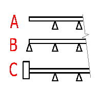
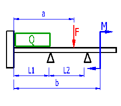
Define in this paragraph the shape and number of supports, free or fixed ends of the beam and loads acting on the beam. A schematic illustration of the beam including loading is shown in the right part of the paragraph. Any changes to definition of the shape and loading are immediately updated in the schematic illustration.
Select the desired system of calculation units in the list box. After switching over the units, all values will be changed immediately.
In the list box, select the type of termination of the left part of the beam.

In the list box, select the number of central supports. The number of supports depends on the type of seating of the beam on the left and on the right.
In the list box, select the type of termination of the left part of the beam.
Depending on the number of supports, one to six input fields for entering lengths of individual fields of the beam are displayed. Enter their lengths. Visually check the entered data in the schematic diagram.

One continuous load of a constant size can be defined for each field of the beam. The existence of a continuous load is signalled by a green rectangle over the respective part of the beam in the schematic diagram.
The value defines co-ordinates of the field origin from the left end of the beam.
In the table, define the size and acting points of all loading forces and loading moments. If the force or moment is non-zero, it is shown in the schematic diagram. Acting points of the force and the moment are measured from the left end of the beam. Red digits indicate the acting point of the force or moment outside the beam.
The basic table allows you to enter 12 forces and 12 moments. In case you need to enter a higher number of forces, another 8 rows for entering forces can be displayed using the switch in the row [1.11]
In this paragraph, select the type of beam, the respective static values and select a material.
In the pop-up list, select the profile which has to be used. Calculated profiles and selected profiles acc. to ANSI/AISC and DIN are available. The standard or specification of the calculated profile is given in parenthesis after the name of the profile.
After selection, the selected profile is shown in the illustration. In case you select a calculated profile, the input fields in which dimensions of the selected profile must be entered are shown to the right of the illustration. Follow the illustration when entering the dimensions.
In case you select a type of standardised profile, the dimensions series is available in a pop-up list. Select suitable dimensions of the profile.
If the desired profile is not included in the database and calculated profiles also do not fit, your own static values of the profile can be entered. In such cases, switch over the selection to Yes and in the row [2.6,2.7 a 2.8] fill in the required values.
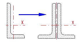
In case the beam consists of several profiles, enter the number of profiles in series. Static values of one profile are multiplied by the entered value.

The rows show static values of the selected profiles. After enabling the switch in row 2.4 you can enter your own values
In the pop-up list, select the material of the calculated beam. Structural steel with strength 36ksi and 50ksi is commonly available for ANSI profiles and structural steel EC 3, EN 10025; Fe 360; Fe 430; Fe 510 for DIN profiles
Characteristic material parameters are necessary for correct calculation and check of a loaded beam.
If you have filled in the required input data and wish to initialise calculation, press the button "Calculation of the beam".
This chapter includes the most important results and graphs of the courses of monitored parameters. The graphs show the course of the given quantity (the name and units are given above the graph) along the beam (horizontal axis, units in mm or inches.
The value gives reaction in the respective support - numbered from the left.
The value gives the biggest negative and positive bending moments. The course - graph "C".
The value gives the minimum (downward) and maximum deflection of the beam. The course - graph "B".
The bending stress is a parameter determining whether the selected profile is able to carry the given load. In case the maximum bending stress exceeds the maximum permitted bending stress of the selected material, the respective cell is shown in red.
Calculation of the total weight of the beam is based on the area of the profile, length of the beam and specific weight of the selected material.
Deformation of the profile and consequential buckling may appear at the free end of the beam. The value of the maximum length of the free end of the beam is informative. Exact values can be found in specialised literature (E.g. Manual of Steel Construction AISC...).
In addition to the maximum permitted stress, the relative deflection in [%] related to the length of the field (of the beam) is another parameter which may decide and usually decides whether the beam is sufficient or not. The maximum permissible relative deflection depends, above all, on the type of structure. Basic recommendations are given here. However, these values must be taken as orientation ones and the values given in the respective directive or standard must be followed.
Graph "E" the bending shows the bending angle of the beam in degrees against the axis of the non-loaded beam.
The slider on row [3.9] may dynamically move the selected force [3.10]. The results will be recalculated immediately after moving the force.
In this paragraph you can find exact values of the monitored parameter at any position along the beam.
Information on setting of calculation parameters and setting of the language can be found in the document "Setting calculations, change the language".
General information on how to modify and extend calculation workbooks is mentioned in the document "Workbook (calculation) modifications".
The calculation itself is executed in the VBA module; therefore, it is not available to the user. In the sheet "Tables" However, it is possible to modify material coefficients and parameters of profiles.
^