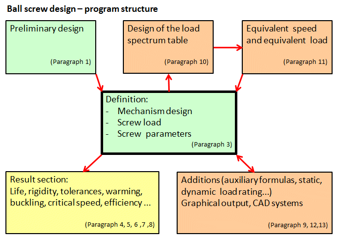
This program (algorithm) is used to design, calculate and check ball screws. It is used to solve the following tasks:
1. Preliminary design (minimum input parameters – sufficient to navigate and select from catalogs)
2. Detailed analysis (load, dimensions, parameter check)
3. Load spectrum table definition (speed, torque, revolutions and power output...)
4. Calculation of an equivalent load
5. Service life calculation, tolerances, temperature analysis
6. Tensile/Pressure, thrust, bend, buckling and critical revolutions
7. Lubrication proposal and efficiency calculation
8. The program contains tables of screws according to ISO and ANSI
9. Support of 2D CAD systems
The calculation is based on data, procedures and algorithms from specialized literature and AGMA, ISO, DIN and BS standards.
List of standards:
ISO 3408-1:2006; ISO 3408-2: 1991; ISO 3408-3:2006; ISO 3408-4:2006; ISO 3408-5:2006; ISO 286-2:2010
DIN ISO 3408; JIS B1192-1997; JIS B1192-2018; DIN 69051-5; ANSI B5.48
Company cataloques: THK, PMI, KSK, NSK, SKF, HIWIN, KURODA, NOOK, THOMSON, Steinmayer, MANESMAN
![]()
User interface.
![]()
Download.
![]()
Purchase, Price list.
Information on the syntax and control of the calculation can be found in the document "Control, structure and syntax of calculations".
Information on the purpose, use and control of the paragraph "Information on the project" can be found in the document "Information on the project".
Ball screws (BS) have a wide range of uses.
They are used, for example, as drives for CNC machines, injection molding machines, replacement for hydraulic drives, medical devices, aviation and automotive technology, transport technology. The advantage of BS is high efficiency of the movement transfer (approx. +90%), the disadvantage is the absence of a self-locking feature.
Ball screws may be divided according to type as follows:
Universal screws used in machining centers, aircraft technology, automotive technology, positioning equipment, etc. Depending on the degree of accuracy, they are produced by grinding or rounding. BS are usually manufactured in IT1-IT5 accuracy classes. Nuts may be preloaded, or without any preload. Most of the calculations in the program are related to this universal group.
Designed for high positioning speeds (up to 30 m/min – work speed, up to 80 m/min – high speed). Machining, positioning, Accuracy IT1, IT3, preload is used. Usually multi-start threads
Designed for high loads and long life. Greater load capacity is achieved by a larger ball diameter, a higher number of threads and profile modification. Manufactured by grinding – for higher accuracy (IT1), with no preload.
Low positioning accuracy, lower speed, low price, no preload. Manufactured by rolling, rounding, accuracy IT5, IT7, IT10. Used for transport mechanisms.
This category includes a number of ball screws such as profileless screws (the shaft is in the form of a ground hardened rod), screws with a cage (balls are in a cage without a converter, smooth run, short strokes), telescopic (several ball screws joined (screwed-in) together, small spacial installation requirements), etc.
Depending on the design, nuts are designed with an external ball guide (noisier, more balls in circulation) or with an internal ball guide. Ball circulation may be designed in several ways. It mostly depends on the manufacturer and the effort to achieve the best possible coefficient of rotation (d1 * nmax).
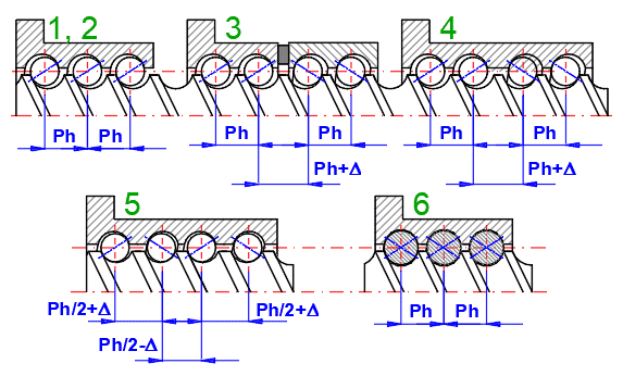
Nuts are mounted on the screw with a free play or as preloaded – to eliminate any free play. The disadvantage of preload is greater wear. Also durability decreases with increasing preload.
1. No preload
2. Preload achieved by an external force on nut/screw
3. Spacer ring shifting the threads of the nut
4. Different thread pitch in the nut
5. By mutual displacement of individual thread starts (for multi-start threads)
6. Using larger (and smaller) ball diameters (4-point contact)
Usually a 10% of the basic dynamic load capacity Ca is used. Individual manufacturers allow and recommend different settings according to the type and purpose of the screw.
Examples of manufacturers:
KSK
3 % Ca - suitable for precise positioning and for smaller loads
5 % Ca - suitable for precise positioning and moderately loaded screws
10 % Ca - suitable for precise positioning and highly loaded screws
THK
10% Ca
Stainmaier
8-10% Ca - for nuts with 2-point contact
5-8% Ca - for nuts with 4-point contact
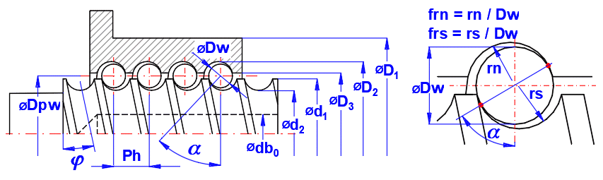
The main geometric parameters of ball screws are the nominal diameter and the pitch of the thread. The design and use of the screw is based on these parameters. The load capacity, stiffness, maximum revolutions (RPM) depend on the size of the diameter, and the travel speed depends on the thread pitch and RPM. Other geometric parameters that affect the functionality include ball size, groove design, degree of accuracy, diameters and nut length, etc.
Other important parameters such as the method of production, material, guaranteed accuracy and lubrication determine the specific use in the relevant structure or device.
Although standards (ISO, ANSI) provide a number of calculations or check parameters, it is always advisable to use the manuals of the relevant manufacturer.
Manufacturers of “inch” screws offer rather standard ball screws. Under comparable conditions, both inch and metric screws offer the same load capacity and service life. The most noticeable difference is the specified service life. For inch screws, the service life is given in inches of travel over the service life, and for metric screws it is given in revolutions over service life. The calculation contains both parameters.
Conversion:
According to ANSI, the dynamic load capacity is the load at which the screw reaches a service life of 1 million inches of travel. According to ISO, the service life is calculated at 1 million revolutions.
Therefore, if the pitch is less than 1 inch, the load capacity according to the ANSI is less than the load capacity of the same ball screw defined according to the ISO/DIN standard.
This also applies to a screw with a pitch greater than 1 inch, but in reverse. A screw with a pitch greater than 1 inch will have a higher load capacity according to ANSI than according to ISO, even if the screw is identical. To compare between ANSI/ISO, it is necessary to perform a recalculation using the following formula:
Pi [lbf] = Ca [N] / (4.44822 * (25.4 / Ph [mm])(1/3))
where:
Ca [N] ...... Dynamic axial load rating ISO
Pi [lbf] ...... Dynamic axial load rating ANSI
Ph [mm] ... Lead
Dimensional markings are often inconsistent in standards, literature or catalogs. This is why we provide symbols/markings for this calculation.
The characteristic speed (Dn = d1 * ns)
Its value is mainly influenced by the design of the ball transfer system. High-revolution screws require the smoothest possible travel path in the transducers and the most accurate transitions of balls returning to the transducer. Manufacturers specify different values for different designs, which depend on the accuracy, the way the balls are transferred (internal/external), etc.
In most cases, the value Dn decreases with the increase in the screw diameter.
Examples of Dn
Manufacturer ........... range
KSK ............... 100000 - 125000
NSK ................ 80000 - 160000
Shuton .......... 100000 - 160000
PMI ................. 80000 - 220000
Steinmeyer ..... 120000 - 160000
When calculating the ball screw, a number of strength checks and additional calculations are performed. The list and formulas used are below.
| Buckling | Critical speed | Deflection | |
| Ball Screw mounting | Coeffb | Coeffncr | Coeffymax |
| Fixed - Fixed | 4 | 4.73 | 0.002604167 (1/384) |
| Fixed - Supported | 2 | 3.927 | 0.0054 |
| Supported - Supported | 1 | 3.14159 | 0.013020833 (5/384) |
| Fixed - Free | 0.25 | 1.875 | 0.125 (1/8) |
y [m] = Coeffymax * (qm * Ls/1000)4) / ((Es * 1000000) * Ix)
Coeffymax ... Coefficient [~]
qm ............. Dead weight load [N/m]
Ls ............... Unsupported length of ball screw [mm]
Es ............... Modulus of elasticity [MPa]
Ix ............... Quadr. moment of inertia [m]
t [MPa] = 16 * Mk / (p * (d2 / 1000)3) / 1000000
Mk ........ Torque [Nm]
d2 ........ Inner diameter of screw [mm]
Ϭ [MPa] = 4 * F / (p * (d2 / 1000)2) / 1000000
F .......... Load force [N]
Ϭred [MPa] = (Ϭ2 + 3 * t2)0.5
Fb = (Coeffb * p2 * Es * Ix) / Ls2
Coeffb ... Buckling factor
ncr = (60 * Coeffncr2 / (2 * p)) * (Es * Ix * 9.81 / ((ros * 9.81 * 0.000000000001) * A * Ls4))0.5
Coeffncr ... Critical speed factor
ros ........... Density [kg/m3]
The basic static load rating (C0a) generally equals to the permissible axial load of a Ball Screw. Depending on the conditions, it is necessary to take into account the following static safety factor against the max. calculated load (unexpected external force may be applied through an inertia caused by the impact or the start and stop).
SFs = C0a / Fmax
Fmax ....... Maximum axial load [N]
C0a ......... Basic static axial load rating [N]
SFs .......... Safety factor
Values should be greater than the following recommendations. It is estimated according to the specified load factor [3.15].
General industrial machinery
Without vibration or impact ........ 1.0 - 3.5
With vibration or impact ............. 2.0 - 5.0
Machine tool
Without vibration or impact ......... 1.0 - 4.0
With vibration or impact .............. 2.5 - 7.0
h = (1 - f * tan( f ))
/ (1 + f / tan( f ))
hr = (1 - f / tan( f )) /
(1 + f * tan( f ))
f .... Friction coefficient
f ... Lead angle
Grease lubrication: According to DIN51825, grade 2 lubricants are generally recommended. Under normal operation they shall be refilled after 6-10 months.
Oil lubrication: In general, the same oils as for roller bearings are used. Recommended viscosity at least 50 mm2/s(cSt)
A number of standards and information from professional or company publications are used in the calculation. In this section you will find the formulas and relationships used without providing detailed explanations and comments. These are available in the original sources. In most cases, these excerpts or statements are given in the original language of the relevant standard.
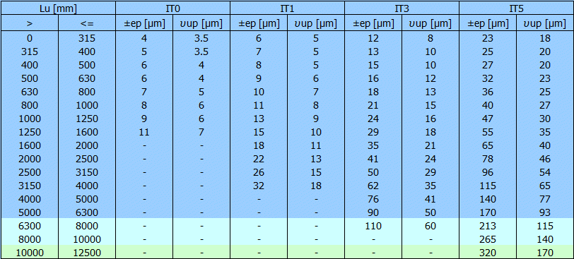
This part of specifies the technical acceptance conditions for ball screws and, in particular, the respective permissible deviations for the acceptance tests.
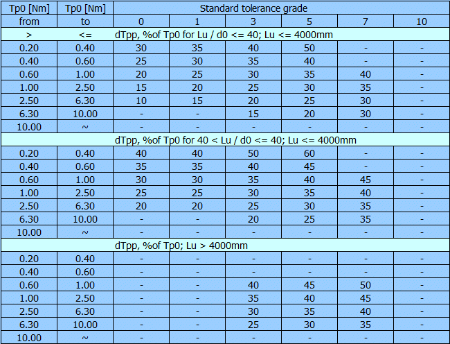
The typical tolerance grades for positioning and transport ball screws
| Type of ball screw | Standard tolerance grade |
| Positioning (type P) | 0 - 1 - 3 - 5 |
| Transport (type T) | 0 - 1 - 3 - 5 - 7 - 10 |
| Travel deviations per reference length | Positioning | Transport |
| Travel compensation c for useful travel Lu | Specified by user | C = 0 |
| Tolerance on specified travel ep | 1.1 | 1.2 |
| Permissible travel variation uup within useful travel | 2 | - |
| Permissible travel variation u300pwithin 300 mm travel | 3 | 3 |
| Permissible travel variation u2pp within 2p rad | 4 | - |
Checking of the mean travel deviations, esa and e0a, within the useful travel
Lu:
a) for the specified travel Ls
b) for the nominal travel L0

(a) Actual travel deviation
Permissible deviations
Checking of the mean travel deviation e0a, within the useful travel Lu:
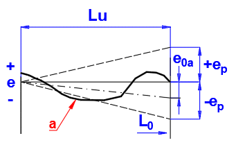
Permissible deviations
| Standard tolerance grade | |||||
| 0 | 1 | 3 | 5 | 7 | 10 |
|
ep = +- (Lu / 300 * u300p) [mm] |
|||||
Checking of the travel variation uu within the useful travel Lu
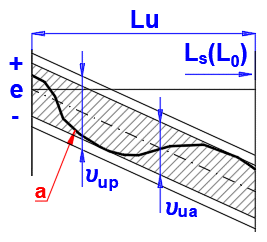
Permissible deviations
Checking of the travel variation u300pwithin 300 mm within an axial travel of 300 mm:
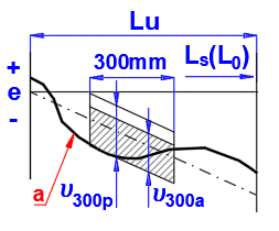
Permissible deviations
| Standard tolerance grade | |||||
| 0 | 1 | 3 | 5 | 7 | 10 |
|
u300p [mm] |
|||||
| 3.5 | 6 | 12 | 23 | 52 x | 210 x |
x - Only for transport ball screws
Permissible travel variation u2pp within 2p rad
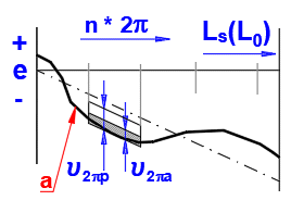
Permissible deviations
| Standard tolerance grade | |||||
| 0 | 1 | 3 | 5 | 7 | 10 |
|
u300p [mm] |
|||||
| 3 | 4 | 6 | 8 | - | - |
Although is a detailed description of the measurement and the resulting values in the standard, it is advisable to consult with the manufacturer or use the company catalogs.
Positioning or transport ball screw. Measurement of dynamic preload drag torque, ΔTp:
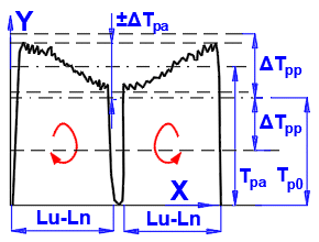
X - Travel
Y - Dynamic preload drag torque
Permissible deviations
Measurement of axial rigidity, Rnu:
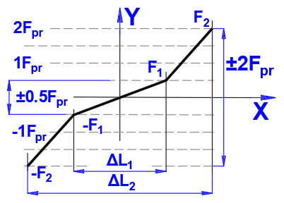
X ... Elastic deformation
Y ... Load
The axial load F1 = 0.5 * FPr or F2 = 2Fpr to the ball screw shaft in tension
and in compression.
Fpr is the preload and ΔL1 or ΔL2
are the elastic deformations (reversal range) caused by the axial test loads ±
F1 and ± F2 respectively.
Rigidity in the ranges ± F1:
Rnu1 = 2 * F1 / ΔL1 = Fpr / ΔL1
Rigidity in the range + F1 to + F2 and - F1 to - F2:
Rnu2 = 2 * (F2 - F1) / (ΔL2 - ΔL1) = 3 * Fpr / (ΔL2 - ΔL1)
Other test loads F may be used by agreement between the user and the manufacturer.
The static axial rigidity R [N/µm], constitutes the resistance to deformation and denotes the force ΔF [N], which is required to effect a component deflection ΔL by 1 µm in the axial direction of load application:
R = ΔF / ΔL
1 / Rbs = 1 / Rs + 1 / Rnu,ar
Static axial rigidity of ball screw shaft, Rs
The rigidity of the ball screw shaft follows from the elastic deflection of the ball screw shaft ΔL caused by an axial force ΔF and depends on the bearing arrangement.
A. Rigid mounting of ball screw shaft at one end
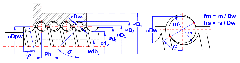
Rs1 = (p * (dc2 - db02) * E) / (4 * Ls * 1000)
dc = Dpw - Dw * cos(a)
Dc = =Dpw + Dw * cos(a)
B. Rigid mounting of ball screw shaft at both ends
Rs2 = (p * (dc2 - db02) * E) / (4 * Ls2 * 1000) * (Ls / (Ls - Ls2))
minimum of rigidity at: Ls2 = Ls / 2
Static axial rigidity of ball nut unit with backlash: Rnu1
Static axial rigidity of nut body and screw shaft under resulting radial
components of load: Rns
Rns = ΔF / ΔLns
ΔLns = ΔF / Rns
Rns = (2 * p * i * Ph * E * tan(a)2) / (((D12 + Dc2) / (D12 - Dc2) + (dc2 + db02) / (dc2 - db02)) * 1000)
Static axial rigidity in ball / balltrack area: Rbt
The axial deflection in the ball / balltrack area is sufficiently approximated by the following equation:
ΔLns = (11)
According to Hertz the approach of the components is calculated from:
ΔLs,nb/t = (12)
Where for the screw shaft balltrack/ball contact applies:
Ʃρs = 4 / Dw - 1 / (frs * Dw) + 2 * cos(a) / (Dpw - Dw * cos(a))
For the nut bailtrack/ball contact applies:
Ʃρn = 4 / Dw - 1 / (frn * Dw) - 2 * cos(a) / (Dpw + Dw * cos(a))
The auxiliary values Ysn depend upon the ratio of the semi-major to the semi-minor axes of the contact ellipse cos(t). The following equation makes use of sin(t), which can be obtained by:
sin(t) = (1 - cos(t)2)0.5
Ys,n = 1.282 * (-0.154 * sin(t)0.25 + 1.348 * sin(t)0.5 - 0.194 * sin(t))
cos(ts) = abs[(-1 / (frs * Dw) - 2 * cos(a) / (Dpw - Dw * cos(a))) / Ʃρs]
cos(tn) = abs[(-1 / (frn * Dw) + 2 * cos(a) / (Dpw - Dw * cos(a))) / Ʃρn]
cEs,n = (11550 * (E0s,n + E0b) / (E0s,n * E0b))1/3
Es = En = Eb = 210000
ms = mn = mb = 10 / 3
E0s = E0n = E0b = E0
cEs = cEn = cEb =0.4643
FN = F / (i * z1 * cos(φ) * sin(a))
z1 = INTEGER ((Dpw * p) / (cos(φ) * Dw) - z2)
φ = arctan (Ph / (Dpw * p)
The rigidity characteristic k of one loaded turn of the ball screw is calculated from:
k = (z1 * sin(a)5/2 * cos(φ)5/2) / (cE3 * ck3/2)
ck = Ys * (Ʃρs)1/3 + Yn * (Ʃρn)1/3
Thus, the axial deflection due to Hertz stress exerted on a single nut can be calculated:
ΔLb/t = (F / (k * i))2/3
d(ΔLb/t) = 2/3 * F-1/3 * (1 / (k * i)2/3) * dF
The static axial rigidity of the ball/balltrack area Rb/t at the axial force F is:
Rb/t = dF / d(ΔLb/t) = 3/2 * (Fe * (i * k)2)1/3
1 / Rnu1 = 1 / Rb,t + 1 / Rn,s
Static axial rigidity of symmetrically preloaded ball nut unit: Rnu2,4
Static axial rigidity of nut body and screw shaft under preload, Rn/s,pr
As both nut bodies act like preloaded rings, the rigidity, Rn/s,pr of a double
nut is twice as high as that of a single nut:
Rn/s,pr = 2 * Rn/s
Static axial rigidity of ball/balltrack area under preload: Rn/t,pr
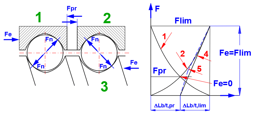
1. ball nut 1
2. ball nut 2
3. ball screw shaft
4. straight approximation line
5. actual curve
(5) Actual curve of the axial deflection in the ball/balltrack area of the
preloaded ball nut system if an additional external load between Fc = 0 and Fc =
Flim is applied.
Maximum deviation between 4 and 5 is approximately 6 %.
The following equation will furnish a guide value for symmetric double nuts:
Fpr = Fm / 23/2
Fm ..... Equivalent load (ISO 3408-5)
Fm = (Ʃ Fej3 * (nj / nm) * qj)(1/3) <j = 1 ... n>
The axial deflection of the ball/balltrack area due to the preload of a symmetrically preloaded nut system:
ΔLb/t,pr = (Fpr / (k * i))2/3
For 0 < Fe <= Flim, the rigidity Rb/t in the ball/balltrack area is determined as follows:
Flim = 23/2 * Fpr
Aproximation result
Rb/t = 23/2 * (Fpr * (k * i)2)1/3
Single or double ball nut preloaded by two-point-ball-contact: Rnu2
1 / Rnu2 = 1 / Rb/t + 1 / Rn/s,pr
Single ball nut preloaded by four-point-ball-contact: Rnu4
1 / Rnu4 = 1 / Rb/t + 1 / Rn/s,pr
As tolerances accumulate during the manufacturing process, differences occur
in rigidity evaluations.
The correction factor takes into account the following influences: machining
inaccuracies of balltrack (travel variations, groove, surface roughness, contact
angle, diameter).
Correction factor for accuracy far
| Accuracy class | far |
| 0, 1 | 0.60 |
| 3 | 0.55 |
| 5 | 0.50 |
| 7, 10 | 0.40 |
The static axial rigidity of the ball nut unit calculated with the
corresponding correction factor is:
Rnu,ar = far * Rnu
Calculations are based on the definition of the dynamic load capacity, under which the ball screw reaches 1 million revolutions. More specifically this means that 90% of a sufficiently large number of identical ball screws will reach this value or service life. This durability or capacity is usually marked as L10. For higher reliability than 90% it is necessary to use the appropriate “far” correction factor.
Basic formula for the nominal life calculation
L = (Ca / Fm)3 * 106
L ...... Life [revolutions]
Ca ... Basic dynamic axial load rating [N]
Fm ... Ekquivalent axial load [N]
and
Lh = L / (60 * nm)
Lh ..... Life [hodiny]
nm .... Equivalent rotational speed [/min]
L1,2 = (Ca / Fm1,2)3 * 106
L1,2 = (Ca / Fma1,2)3 * 106
Lr = (L1-10/9 + L2-10/9)-9/10
Lar = L * far; resp. Lar = Lr * far
far ... Reliability factor
| Reliability [%] | far |
| 90% | 1.00 |
| 95% | 0.62 |
| 96% | 0.53 |
| 97% | 0.44 |
| 98% | 0.33 |
| 99% | 0.21 |
In the same way, the modified life
Lm, Lhm is calculated:
Lm = (Cam / Fm)3 * 106
;Lhm = Lm / (60 * nm); Lm1,2 = (Cam / Fm1,2)3 * 106
...............
L = (Ca / (fw * Fm))3 * 106
fw ... Load factor
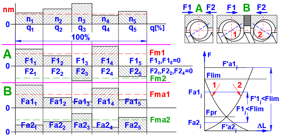
In the case of variable rotational speed and variable axial load, the equivalent values Fm and nm are used for the life calculation:
At variable rotational speed the following applies for the equivalent rotational speed nm [/min]:
nm = Ʃ (qj / 100) * nj <j = 1 ... n>
q ... Time [%]
n ... Rotational speed [/min]
At variable axial load and variable rotational speed, the following applies for the equivalent axial load Fm [N]:
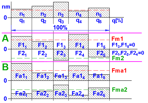
Fm = (Ʃ Fj3 * (nj / nm) * (qj / 100))(1/3) <j = 1 ... n>
F ... Axial load, force [N]
Fm1,2 = (Ʃ F1,2j3 * (nj / nm) * (qj / 100))(1/3) <j = 1 ... n>
Due to the application of an external axial load to a preloaded ball screw (backlash elimination between nuts and screw shaft), one ball nut will be additionally loaded and the other relieved.
Flim = 23/2 * Fpr
The preloaded ball nut (1) or (2)
will be additionally loaded by an external axial load. The actual axial load to
this ball nut is
- for the external load F1j or F2j <= Flim, the following equation:
Fa1,2 = fop * Fpr * (1 + F1,2j / (23/2 * fop * Fpr)3/2
fop ... Operational preload factor (0.6)
F ...... Axial load, force [N]
Fa .... Actual axial load [N]
Fpr ... Preload [N]
- for the external load F1j or F2j > Flim, then:
Fa1j = F1j , Fa2j = F2j and Fa1j = 0, Fa2j = 0
For the calculation for the equivalent actual axial load:
The basic axial load rating is calculated from the following equations:
C0a = k0 * z1 * i * sin(a)
* Dw2 * cos(φ)
z1 = INTEGER ((Dpw * p)
/ (cos(φ) * Dw) - zu)
φ
= arctan (Ph / (Dpw *
p)
k0 = 27.74 / (Dw * (( ρ11 +
ρ12) * ( ρ21 +
ρ22))0.5
ρ11 = ρ21
= 2 / Dw
ρ12 = -1 / (frs * Dw)
ρ22 = cos(a)
/ (Dpw / 2 - cos(a) * Dw / 2)
a ........ Contact angle [°]
φ
........ Lead angle [°]
i ......... Number of loaded turns [~]
Dw ..... Ball diameter [mm]
Dpw ... Ball pitch circle diameter
In the case of optimal load distribution (parallel
load directions in ball screw shaft and in ball nut), the basic dynamic axial
load rating is derived from the following basic interrelations:
Ca = Ci * i0.86
Ci = Cs * (1 + (Cs / Cn)10/3)-0.3
Cs = fc * cos(a)0.86
* z12/3 * Dw1.8 * tan(a) * cos(φ)1.3
fc = 9.32 * f1 * f2 * (1 / (1 - 1 / (2 * frs)))0.41
f1 = 10 * (1 - sin(a) /
3)
f2 =
g0.3
* (1 -
g)1.39 / (1 +
g)1/3
g = Dw / Dpw *
cos()
Cs / Cn = f3 * ((2 - 1 / frn) / (2 - 1 / frs))0.41frn = rn / Dw
frs = rs / Dw
f3 = ((1 -
g) / (1
+ g))1.7233
C0am = C0a * fh0 * fac
Correction for surface hardness, fh0
fh0 = (AH / 654)3 ≤ 1.0
AH ... actual hardness [HV10]
Correction for accuracy, fac
| Accuracy class | fac |
| 0, 1, 3, 5 | 1.00 |
| 7 | 0.90 |
| 10 | 0.70 |
Cam = Ca * fh * fac * fm
Correction for surface hardness, fh
fh = (AH / 654)2 ≤ 1.0
AH ... actual hardness [HV10]
Correction for accuracy, fac is the same as for static axial load
Material factor fm
| Ball bearing steel | fm |
| Air melted | 1.00 |
| Vacuum degassed | 1.25 |
| Electro slag remelted | 1.44 |
| Vacuum remelted | 1.71 |
The following equations for the basic load rating and static thrust capacity are included to enable the user of this standard to determine the approximate size ball screw assembly necessary to meet requirements.
Imperial (Inch) System Symbols
Pi ...... Basic load rating (1 000 000 inches rated life), [lbf]
Pix .... Rated load at x inches rated life, [lbf]
Ti ...... Basic thrust capacity, [Ibf]
LIi ..... 1 000 000 inches rated life, [inches]
LIix ... X inches rated life, [inches]
di ...... Ball diameter, [inches]
n ....... Number of ball turns under a unidirectional load, [turns]
Li ...... Lead, [inches / revolution]
Z ....... Number of load carrying balls per turn, [balls
/ turn]
Pi = 4500 * Z2/3 * di1.8 * n0.86 * Li1/3 , [lbf]
Ti = 10 000 * n * Z * di2 , [lbf]
Pix = Pi * (LIi / LIix)1/3 , [lbf]
Usually, the design cannot be solved directly and the parameters must be continuously specified or modified. However, for the most common solutions (when you know the load forces, feed speed and positioning accuracy), we recommend the following procedure.
1. In paragraph [1.0], select the units and perform the preliminary design. Check accuracy requirements.
2. In paragraph [3.0], select/enter the screw parameters (diameter, pitch, accuracy, load...) based on the preliminary design.
3. If you do not know the exact load parameters, go to paragraphs [10.0] and [11.0].
Here you can define the load table [10.0] and calculate the equivalent load [11.0].
(For accurate calculation of the load, it is necessary to know the dimensions of the screw, so it is advisable to use the preliminary design for estimation)
4. After entering/changing the input parameters [3.3-3.44], you can immediately check the most important parameters [3.45-3.57].
5. A detailed list of all results may be found in the Results section.
The design of the ball screw cannot be solved directly. When designing the project, it is necessary to take into account a number of often conflicting requirements and, therefore, the solution may be found through gradual refinement of the design followed by checking the parameters of the screw in the manufacturer's (supplier's) catalog.
Therefore, in this section, it is possible to roughly design the dimensions of the screw, revolution, feed rate, check critical revolutions, check the screw for buckling and determine the accuracy and the required engine power. Using the following chapters you may optimize the preliminary design and propose and check all parameters in detail.
Select the desired system of calculation units in the list box. After switching over the units, all values will be changed immediately.
At the same time, the selection tables are reset to match the selected units (ISO/ANSI).
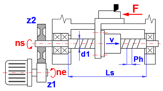
Most tasks require the speed of the trolley (carrier) based on the pitch, screw revolutions, gear ratio and engine speed. This is solved in this section. Check the option to the right of the input cells to specify which value you wish to calculate.
The range of pitch Ph with respect to the diameter of the screw d1 is given in Table [1.32]. Follow the picture when selecting the values.
Standard series of the lead - mm (ISO, JIS, DIN, BS ...)
1; 2; 2.5; 3; 4; 5; 6; 8; 10; 12; 16; 20; 25; 32; 40 [mm]
Standard series of the lead - inch (ANSI)
0.08; 0.1; 0.125; 0.16; 0.2; 0.25; 0.333; 0.375; 0.4; 0.5; 0.75; 1.0 [in]
To select, use the list on the right.
The gear ratio is defined as the ratio of the number of teeth i = z2/z1. If you use a direct screw drive, i = 1.
1. Enter the equivalent screw load [1.9]. Simply enter your estimate of the screw load (what weight you intend to lift, what force you use to inject the relevant material, what force acts on the part during machining...). Do not forget to include the effect of vibrations and impacts/shocks. If vibration or impacts are strong, the load may be two or three times greater (see coefficient fw [1.11]).
2. Enter the equivalent revolutions [1.10]. Approximate revolutions when the screw is under the highest load.
3. Enter the required durability (service life) in hours [1.11]. (For preliminary purposes, you can select a value of about 20,000 hours)
Based on the specified equivalent load force, revolutions and required durability, the required dynamic load capacity "Ca-req" ("Pi-req" according to ANSI) is calculated. The diameter of the screw is found based on the dynamic load capacity. The proposed screw diameter ranges from the minimum value of the diameter of the nut with five-threads to the maximum diameter of a single-thread nut. The number of the threads is given in parentheses after the diameter.
If the button is checked, the values from line [1.5] are automatically transferred.
fw = 1.0 … 1.2 for almost no vibration, no impact load (v ≤ 0.25 m/s)
fw = 1.2 … 1.5 for slight vibration, impact load (0.25 < v
≤ 1.00 m/s)
fw = 1.5 … 2.0 for middle vibration, impact load (1.00 < v
≤ 2.00 m/s)
fw = 2.0 … 3.5 for severe vibration, impact load (v
> 2.00
m/s)
It is possible to choose between several input options. For mm screws the service life is given in hours (less often in screw revolutions). For inch screws the service life is given in inches (or in [m]) of travel. When change is applied, the input value is automatically recalculated so that the required dynamic load capacity remains the same.
Orientation values in hours are given
below.
Machines for short-term runs 5000 -10000
Machines for 8-hour operation 20000
Machines for 16-hour operation 40000
Machines for continuous operation 80000
Based on the load, revolutions and the required service life, the required dynamic load capacity is calculated. The selected screw should meet higher load capacity.
This is a value that is converted from an ISO value to an ANSI value. More information available in the theoretical part of the help feature.
The proposed screw diameter ranges from the minimum diameter with five-thread nut to the maximum diameter with a single thread nut.
The diameter is designed based on the load capacity Ca calculated according to ISO3402-5.
After selecting the mounting method and the length and diameter of the screw (see pictures), all important check values are calculated. You can immediately check the value of the revolution factor, the maximum buckling force and the maximum allowed revolutions. At the same time you may estimate the tolerance class of the screw depending on the required positioning accuracy.
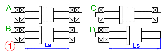
Select the method of radial mount of the ball screw as shown in the picture. The mounting method affects the buckling strength and critical revolutions. If the nut is rotating it is not necessary to check the critical revolutions.
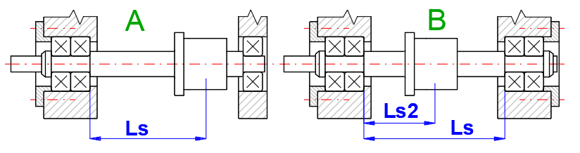
Enter the length of the unsupported part of the screw Ls (see the picture). Generally, length less than 40 screw diameters is recommended.
Standard range of ISO diameters [mm]
6, 8, 10, 12, 16, 20, 25, 32, 40, 50, 63, 80, 100, 125, 140, 160, 200
Diameters used by manufacturers [mm]
4, 6, 8, 10, 12, 14, 15, 16, 20, 25, 28, 32, 36, 40, 45, 50, 63, 80, 100, 125, 140, 160, 200
Standard range of ANSI B5.48-1977 diameters [in]
0.25, 0.3125, 0.375, 0.5, 0.625, 0.75, 0.875, 1, 1250, 1.5, 1.75, 2, 2.25, 2.5, 3, 3.5, 4, 4.5, 5, 6, 8
The characteristic speed (Dn = d1 * ns)
Its value is mainly influenced by the design of the ball transfer system. High-revolution screws require the smoothest possible travel path in the transducers and the most accurate transitions of balls returning to the transducer. Manufacturers specify different values for different designs, which depend on the accuracy, the way the balls are transferred (internal/external), etc.
In most cases, the value Dn decreases with the increase in the screw diameter.
Examples of Dn
Manufacturer ........... range
KSK ............... 100000 - 125000
NSK ................ 80000 - 160000
Shuton .......... 100000 - 160000
PMI ................. 80000 - 220000
Steinmeyer ..... 120000 - 160000
It is used to calculate efficiency. A value of 0.01 may be selected for the preliminary design.
Depending on the length of the screw Ls, the tolerance for individual tolerance classes is determined. Using the values from the table, you can also estimate/select the required accuracy of the screw.
ISO: For positioning screws (P-type) the IT0-IT5 classes are used, and for transportation screws (T-type) the IT1-IT10 classes are used.
ANSI: Used scale – Class 1 to Class 8.
Detailed explanation is available in the theoretical part and in Section [6.0].
The table shows the screw diameters and the pitch range according to ISO and ANSI standards. Asterisks indicate diameters offered by some manufacturers beyond the ISO standard.
After selecting the screw from the table, the diameter is transferred over to line [1.19].
In this section you can define material parameters. The basic setting, which is steel, is suitable for the vast majority of cases. Confirm by pressing the button. Only a specialist or the manufacturer should change these values.
In this section you define all input parameters of the ball screw gear ratio. Start with the accuracy, screw mount, load, length, load capacity, etc. After defining all parameters, all screw parameters are available in the "Results" section, which are evaluated and monitored in real life.
When selecting parameters, use the help feature for each parameter. You may also use additional calculations available in the "Add-ons" section.
Press the "[1.0]>>[3.0]" button to transfer the values (Ph, Fm, nm, fw, L, Ls, d1) from the preliminary design into this paragraph.
If the selection from Table [3.26] is set, the system finds the corresponding screw d1 (or the next higher one).
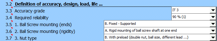
In this section you define the accuracy, design, load and service life.
Based on the type of the screw and on the preliminary design, you should be able to select the appropriate tolerance class. Tolerance classes IT0-IT5 are used for positioning screws, and tolerance classes IT1-IT10 are used for transport screws.
The choice of the tolerance class primarily affects the positioning accuracy, tolerances (paragraph [6.0]), and to a lesser extent the load capacity, the achieved speed and, of course, the price.
Common engineering procedures work with 90% reliability. This means that 90% of the screws can withstand the declared load during the required service life. However, there are sectors where higher reliability is required (aviation, aerospace, nuclear energy...). Therefore, it is possible to set the required reliability higher – which affects the required dynamic load capacity.
Select the method of radial mount of the ball screw as shown in the picture. The mounting method affects the buckling strength and critical revolutions. If the nut is rotating it is not necessary to check the critical revolutions.
In real life there are two methods used to determine axial bearings/mounts of the ends. In the first case, one end is firmly anchored and the other end is free in the direction of the screw axis, in the second case both ends are firmly anchored. The second case is used when it is necessary to apply pre-tension to the screw (for example, elimination of thermal expansion, increase of axial stiffness, etc.).
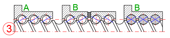
Two types of nuts are used.
A. No preload. It is assumed that the accuracy and load are only important in one direction of movement. When the opposite direction of movement is required, it is necessary to also take free play into account.
B. With preload. The nut is structurally designed so that there is no free play when moving from one direction to another. The design can offer a number of variants and according to the design requirements, the size of the preload also changes (usually it is necessary to agree with the supplier).
The preloaded nut and the amount of the preload affect the calculation of the equivalent screw load. We can picture the situation as follows. Even if the nut is not loaded, the preload creates a force that must be considered when calculating the equivalent load.
When calculating the force for the equivalent load, three cases may occur.
- Zero load force. The preload force is divided in both directions.
- The load force is less than Flim. The load force together with the preload force is proportionally distributed in both directions.
- The load force is greater than Flim. The load force exceeds the preload force and it is only considered in the appropriate direction.
For a detailed description, see paragraph [11.0]
Enter the load in one direction and then in the other direction. In case of a variable load, also enter the equivalent load, see paragraph [11.0].
Enter the maximum axial load. Must be greater than or equal to Fma1, Fma2.
Enter the revolutions in one direction and then in the other direction. In case of a variable revolution, also enter the equivalent revolutions, see paragraph [11.0].
Enter maximum revolutions. Must be greater than or equal to nm1, nm2.
According to the required positioning accuracy and the required rigidity, the method of fitting the nut onto the shaft is selected. The durability (service life) decreases with the increase in the preload. Nut with free play - Unidirectional load Fpr = 0.
The size of the preload is usually specified in the catalog, or it is possible to consult it with the supplier. In general, the following preload values are used – expressed as a percentage of the dynamic load capacity of the screw Ca:
3 % Ca - suitable for precise positioning and for smaller loads
5 % Ca - suitable for precise positioning and moderately loaded screws
8 % Ca - for nuts with 4-point contact
10 % Ca - suitable for precise positioning and highly loaded screws
fw = 1.0 … 1.2 for almost no vibration, no impact load (v ≤ 0.25 m/s)
fw = 1.2 … 1.5 for slight vibration, impact load (0.25 < v
≤ 1.00 m/s)
fw = 1.5 … 2.0 for middle vibration, impact load (1.00 < v
≤ 2.00 m/s)
fw = 2.0 … 3.5 for severe vibration, impact load (v
> 2.00
m/s)
It is possible to choose between several input options. For mm screws the service life is given in hours (less often in screw revolutions). For inch screws the service life is given in inches (or in [m]) of travel. When change is applied, the input value is automatically recalculated so that the required dynamic load capacity remains the same.
Orientation values in hours are given
below.
Machines for short-term runs 5000 -10000
Machines for 8-hour operation 20000
Machines for 16-hour operation 40000
Machines for continuous operation 80000
Based on the load, revolutions and the required service life, the required dynamic load capacity is calculated. The selected screw should meet higher load capacity.
This is a value that is converted from an ISO value to an ANSI value. More information available in the theoretical part of the help feature.
In this section you will select the appropriate screw (nut), or you will fill in the appropriate parameters from the manufacturer's catalog.
Enter the length of the unsupported part of the screw Ls (see the picture). Generally, length less than 40 screw diameters is recommended.
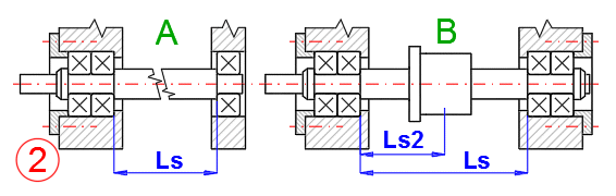
In case of double axial mounts of the screw (variant B), also enter the coordinate of the nut Ls2.
The number of threads is determined by the construction of the nut and is usually specified by the manufacturer. Number of threads between 1.5-6.0 is usually used. The number of threads affects the calculation of static and dynamic load capacity, stiffness and the length of the nut.
Enter the number of balls with no load. This refers to the return system where the balls are returned after one revolution and usually zu = 3. As for return systems where the balls are returned from the final thread back to the first thread, zu = 0. Information on a specific construction can usually be found in the manufacturer's catalog.
The factor expresses an uneven load distribution if the nut has several threads. Thus, if the nut has more threads, the load capacity Ca is calculated according to Ca=Ca(1)*i^exp, where Ca (1) is the load capacity of one thread. This applies similarly to Pi (inch screws).
The calculation contains two basic dimensional tables of screws. Millimeter (ISO) and inch (ANSI). The tables contain all combinations of screw diameters and pitches. Manufacturers adhere to these basic dimensions (or offer more screw diameters). However, the ball diameters may be freely selected. Based on the analysis of many catalogs of various manufacturers, we have prepared a table of used ball diameters and their assignment to the diameters of screws. This created a series marked as light, medium and heavy (ball size), for which the relevant values were calculated C0a, Ca, Ti, Pi.
Catalogs are usually seen as a subset of these tables, and it is usually possible to find a specific screw that meets the calculated parameters.
Select the suitable screw from the list. The screw should meet the following condition – the value of the dynamic load capacity shall be Ca > Ca-reg [3.17] (or rather Pi > Pi-reg [3.18] for inch screws). At the same time, the value of the pitch Ph from the preliminary design [1.0], where you have defined the speed of movement of the nut and thus the required pitch Ph should be observed.
The inner hole of the screw is used to install cooling or to change the critical speed. Most screws are without hole db0 = 0.
The diameter is usually a design issue for the manufacturer. Of course, it is not possible to choose it arbitrarily. The basic condition is that the diameter Dw cannot be greater than the pitch Ph.
0.600, 0.800, 1.000, 1.200, 1.250, 1.500, 1.588, 1.750, 2.000, 2.381, 2.500, 3.000, 3.175, 3.500, 3.969, 4.762, 5.000, 5.556, 6.000, 6.350, 7.144, 7.938, 8.000, 9.525, 10.000, 10.319, 12.700, 20.000, 20.638, 25.400, 30.000, 31.750, 38.100, 40.000, 44.450, 50.000
Standard series of the lead - mm (ISO, JIS, DIN, BS ...)
1; 2; 2.5; 3; 4; 5; 6; 8; 10; 12; 16; 20; 25; 32; 40 [mm]
Standard series of the lead - inch (ANSI)
0.08; 0.1; 0.125; 0.16; 0.2; 0.25; 0.333; 0.375; 0.4; 0.5; 0.75; 1.0 [in]
The pitch diameter is calculated using the d1 and Dw. If you want to enter a custom value, uncheck the button on the right.
In most cases it is 45°.
Conformity (frs, frn) ratio of the ball track radius of the ball screw shaft, rs, or of the ball nut body, rn, to the ball diameter, Dw
If you wish to define your own parameters, enter the load capacity from the manufacturer's catalog.
The value is proposed according to DIN69051-5.
The switch is used to display (see the picture on the right) and to calculate the nut length [3.43] and the working path [3.44] and to provide output for CAD.
After unchecking the button on the right, you can enter your own value.
This section lists the most important values from the Results section.
This section lists the durability (service life) values according to ISO3408-5 (ANSI_B5.48).
If the screw is only stressed along one direction (Fma1 or Fma2 = 0; [3.8,3.9]) and no preloaded nut is used, a simple durability calculation formula is used.
This section includes two options.
- Screw loaded in both directions (without preloaded nut).
- Unidirectionally and bidirectionally loaded screw with preloaded nut. The preloaded nut represents additional internal (bidirectional) load of the screw, which must be taken into account even when only considering unidirectional load.
The calculation then takes into account the bidirectional stress while calculating the durability. (Index 1.2 indicates direction).
This paragraph contains the stiffness calculation according to ISO 3408-4.
The setting change is reflected in paragraph [3.0].
In this section, you can address the overall stiffness of the screw, nut, bearing and mounting assembly.
Support Bearing Rigidity varies depending on the type of Bearing and amount of Preload. Please inquire Bearing manufacturers.
The rigidity of the nut mounting part varies depending on the machine design.
The deformation is calculated for the maximum force Fmax [3.10] and for the full length of the screw Ls [3.20].
These are continuous values for the stiffness calculation. Details in ISO3408-4.
This part of specifies the technical acceptance conditions for ball screws and, in particular, the respective permissible deviations for the acceptance tests.
You may change the tolerance class as needed. The change will also be reflected in paragraphs [3.0, 5.0].
Portion of the travel to which the specified accuracy (stroke plus ball nut body length) is applicable.
The right side shows the value estimated based on the length of the screw and the length of the nut. After unchecking the button, you may enter your own value.
The table shows the most important tolerance values for the entire range of lengths – Lu. At the same time, the column and row for the current length and tolerance class of the screw are marked.
The table shows the complete tolerances according to the pictures on the right for the current Lu value.
The values only apply to preloaded nuts, 100 rpm and viscosity ISO_grade100.
Values F1 = 0.5*Fpr and F2 = 2*Fpr are used for measurements. Theoretical values are used in the calculation. After unchecking the button on [6.16], you may enter your own values.
A table of values according to ANSI_B5.48 is available.
The total allowable variation, peak-to-peak, in lead error over the total thread length.
The maximum permissible positive or negative slope, of the measured lead error line. It is normally specified in inches (mm) of error per 12 inches (300 mm) of thread length.
The total variation, peak-to-peak, in lead error for one revolution of the nut.
During operation the screw and nut temperature increases, which affects the accuracy. Basically, this issue is addressed in three ways, or through a combination thereof.
- it is handled by the control system of the screw drive (nut)
- cooling is applied to the screw (inner bore, coolant)
- by preloading the screw in the axial direction (only for screw mounted on both ends)
This section will help you to determine the expansion of the screw due to the increase in temperature and define the preload force required to eliminate thermal expansion.
When checked, the values from paragraphs [3] and [2] are filled in.
Enter the increase in screw temperature during operation.
Requirement on the change in the shaft length using preload. A checked button automatically fills in the value from [7.6]
This paragraph lists the basic control calculations used to design the ball screw. Green fields offer recommended values.
The input parameters are loaded from paragraph [3.0].
You may change the mounting method. The change will also be reflected in paragraph [3.0].
Depending on the design, an additional axial load may occur, which must be taken into account. If such additional load occurs, enter its value.
It indicates the deflection of the screw due to the weight of the screw for horizontally mounted bolts.
Recommended maximum deflection is
for:
General engineering y = 0.0003 * Ls
Construction of machine tools y = 0.0002 * Ls
To check and calculate the safety, a treated steel alloy is considered (Refined and alloyed steel) with yield strength of Rp0.2 as defined in [2.0].
In case of simultaneous action of tensile stress/pressure and torsion, it is necessary to deal with combined stress and loads. The reduced stress should be less than the allowed tensile stress.
Limiting slenderness SRc is an
important parameter of a specific material, distinguishing the area of elastic
and inelastic buckling as well as the use of relevant equations. It is,
therefore, suitable to verify the parameter for the specific material. The
recommended value is determined according to the equation:
SRcs = 0.5 * (E / (Rp02 * 0.5))0.5
SRc = (E *
p2
/ (Rp02 * 0.5))0.5
The slenderness ratio of a specific screw determines which buckling zone the screw is in (simple compression, inflexible buckling, flexible buckling) and thus also the check method used for determination of the safety coefficient.
A. SR < SRcs..............Area
of simple compression.
Recommended safety SF>1.75)
B. SRcs < SR < SRc.....Area
of
nonelastic
buckling. Recommended safety
SF=1.75*(1+(SR - SRcs) / (SRc - SRcs))
C. SRc < SR................Area
of
elastic buckling. Recommended
safety SF>3.5)
It expresses the ratio between critical and acting force. The minimum safety factor (green cell) is recommended based on the slenderness ratio [8.21]
The screw revolutions should not exceed 80% of the critical speed/revolutions.
Values should be greater than the following recommendations. It is estimated based on the specified load factor [3.15].
General industrial machinery
Without vibration or impact ........ 1.0 - 3.5
With vibration or impact ............. 2.0 - 5.0
Machine tool
Without vibration or impact ......... 1.0 - 4.0
With vibration or impact .............. 2.5 - 7.0
Oil lubrication is recommended for high-speed, high-performance screws. This section is designed for this category of screws. Based on the screw diameter and revolutions, the oil viscosity and minimum oil volume are recommended. At the same time, the efficiency is also estimated.
Oils with wear inhibiting additives should be used. These have the ability to lubricate in conditions of boundary friction, when speeds for EHD-lubrication (elasto-hydrodynamic lubrication) are insufficient. Recommend is the CLP grade gear oil per DIN 51517-3 or equivalent.
You can select the operating temperature, the oil type and, after unchecking the buttons on the right, you may select your own values for the oil viscosity class or simply the viscosity.
When the [8.42] button is checked, the viscosity is calculated based on the operating temperature and the selected viscosity class (VG2-VG1500).
Use the selection button to select the calculation for either a single screw/nut or for a screw/nut + bearings.
Based on the screw dimensions, screw load, bearing load, oil type and viscosity, the coefficient of friction is estimated. This coefficient determines the efficiency. After unchecking the button on the right, you can enter your own coefficient.
The calculation is based on the screw geometry and on the coefficient of friction [8.44]. If you do not have the option to perform laboratory measurements, this may be a suitable parameter to conduct other specialized calculations (heating, heat loss, thermal expansion, etc.).
Normal operation refers to the conversion of rotational force into axial force. Inverse operation refers to the conversion of axial force into rotational force.
In this section, you will find some basic formulas that can help with your design.
In this paragraph you can precisely define the parameters of the mechanism and the load spectrum of the screw and nut. This way you will get accurate values of forces, torques and the required engine power. You can transfer the resulting forces and revolutions into the Equivalent load calculation section [11].
Follow the picture when defining the mechanism.
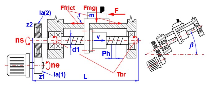
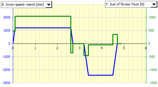
You can monitor a number of parameters in the diagram (revolutions, forces, torques and engine power).
The X-axis represents the time.
Define all parameters. By checking the button on [10.2], the parameters of the screw from paragraph [3.0] are automatically transferred. After unchecking, you can define different dimensions.
The actual length of the screw L is estimated from the specified distance between the bearings Ls, and it is increased by 10 screw diameters. It is only used to calculate the inertia moment.
Most bearing moments are constructed in a horizontal (0°) or vertical (90°) plane. Enter the turning of the mechanism.
Enter all weights of the objects which are moved by the screw.
Moment of inertia converted from the linear motion (table, workpiece...) to rotation movement.
Moment of inertia of the screw shaft.
Moment of inertia of all wheels (rotating masses) on the screw side. You can use the formulas from paragraph [9] to calculate the approximate values.
Moment of inertia of all wheels (rotating masses) on the motor side, including rotating masses of the motor (to find this information consult the motor manufacturer's catalog). You can use the formulas from paragraph [9] to calculate the approximate values.
The gear ratio is defined as the ratio of the number of teeth i = z2/z1. If you use a direct screw drive, i = 1.
However, even in this case it is suitable to define the rotating masses on the motor side (motor, clutch...) [10.11].
Moment of inertia of all rotating masses relative to the drive (motor). It is used to calculate the angular acceleration.
According to the required positioning accuracy and the required rigidity, the method of fitting the nut onto the shaft is selected. The durability (service life) decreases with the increase in the preload. Nut with free play - Unidirectional load Fpr = 0.
The size of the preload is usually specified in the catalog, or it is possible to consult it with the supplier. In general, the following preload values are used – expressed as a percentage of the dynamic load capacity of the screw Ca:
3 % Ca - suitable for precise positioning and for smaller loads
5 % Ca - suitable for precise positioning and moderately loaded screws
8 % Ca - for nuts with 4-point contact
10 % Ca - suitable for precise positioning and highly loaded screws
Torque is required to rotate the preloaded nut, even if the nut is not axially loaded.
Select the coefficient of friction in the guide.
For linear ball guides, the coefficient of friction f = 0.003-0.006.
The following values may be used for shear, lubricated friction guides.
f = 0.05-0.10 ... Hardened steel / Hardened steel
f = 0.05-0.15 ... Hardened steel / Cast iron
f = 0.09-0.15 ... Hardened steel / Bronze (phosphor)
f = 0.07-0.10 ... Cast iron / Cast iron
f = 0.07-0.10 ... Cast iron / Bronze (phosphor)
Enter the efficiency of the ball gear. The recommended value is to the right of the input cell. The value is based on the screw geometry and does not include other effects. However, it is quite sufficient for this proposal.
Enter the friction torques of the bearings. The approximate value is to the right of the input cell.
After pressing the button, the calculated values of forces and revolutions will be moved to the table, which is designed for the calculation of the equivalent load and equivalent revolutions in paragraph [11.0].
Gradually define the work cycle of the mechanism in the table.
Revolution: In the "neend" column, gradually enter the final engine revolutions.
Time interval: In the "dt" column, enter the length of each section in seconds.
Machining force: Enter the external force in the "F” column – if it acts in the given section (e.g. machining).
Line 1: neend=2000; dt=0.05; F=0 ............... Start-up from 0 to 2,000 RPM (acceleration)
Line 2: neend=2000; dt=0.40; F=1000 .......... Machining work cycle at 2,000 RPM machining force is 1,000N
Line 3: neend=0; dt=0.05; F=0 ............... Braking from working speed down to 0. (deceleration)
Line 4: neend=0; dt=0.10; F=0 ............... Time delay (for example for tool readjustment)
Line 5: neend=-2000; dt=0.05; F=0 ................ Start up for reverse run to -2,000 RPM (acceleration)
Line 6: neend=-2000; dt=0.40; F=0 ................ Reverse run at -2000 RPM, machining force 0N
Line 7: neend=0; dt=0.05; F=0 ............... Breaking down to zero RPM (deceleration)
Line 8: neend=0; dt=0.10; F=0 ............... Time delay (for example for tool readjustment)
Total work cycle time 1.2 sec.
Calculations of screw durability (service life) are based on the assumption that the screw operates under constant operating conditions. In practice, however, this assumption is not met. Therefore, you can use this auxiliary calculation, which converts the variable load and variable revolutions into the equivalent load used in the durability calculation.
You may also use the previous paragraph [10], which allows you to define precise parameters of the mechanism and the load spectrum, which results in a precise definition of forces and revolutions for this calculation.
If you do not use the calculation in paragraph [10], proceed as follows when calculating the equivalent load:
1. Divide the work cycle of the screw into several time intervals where the operating conditions are approximately constant (see the picture).
2. Set the number of these time intervals in the selection list [11.2].
3. Select the nut type A or B [11.3] and preload size [11.4].
4. Define the operating conditions for the individual intervals in the input table [11.7].
You can then transfer the calculation results to paragraph [3.0].
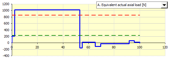
You can follow the curves of the input values in the graph on the right. Also the equivalent load and equivalent revolutions (green direction 1, red direction 2) are also displayed.
The X coordinate indicates the percentage of load (revolutions) at the specified level (the entire load cycle = 100%).
After pressing the button, the values from this paragraph are transferred into paragraph [3.0].
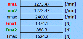
Moved values:nm1, nm2, nmax, Fma1, Fma2, Fmax
In case of a preloaded nut, the value of the preload Fpr [11.4] is transferred as well.
Enter the number of load statuses. If the values are transferred from the previous paragraph [10], it is set automatically.
Two types of nuts are used.
A. No preload. It is assumed that the accuracy and load are only important in one direction of movement. When the opposite direction of movement is required, it is necessary to also take free play into account.
B. With preload. The nut is structurally designed so that there is no free play when moving from one direction to another. The design can offer a number of variants and according to the design requirements, the size of the preload also changes (usually it is necessary to agree with the supplier).
The preloaded nut and the amount of the preload affect the calculation of the equivalent screw load. We can picture the situation as follows. Even if the nut is not loaded, the preload creates a force that must be considered when calculating the equivalent load.
When calculating the force for the equivalent load, three cases may occur.
- Zero load force. The preload force is divided in both directions.
- The load force is less than Flim. The load force together with the preload force is proportionally distributed in both directions.
- The load force is greater than Flim. The load force exceeds the preload force and it is only considered in the appropriate direction.
According to the required positioning accuracy and the required rigidity, the method of fitting the nut onto the shaft is selected. The durability (service life) decreases with the increase in the preload. Nut with free play - Unidirectional load Fpr = 0.
The size of the preload is usually specified in the catalog, or it is possible to consult it with the supplier. In general, the following preload values are used – expressed as a percentage of the dynamic load capacity of the screw Ca:
3 % Ca - suitable for precise positioning and for smaller loads
5 % Ca - suitable for precise positioning and moderately loaded screws
8 % Ca - for nuts with 4-point contact
10 % Ca - suitable for precise positioning and highly loaded screws
Limit load at which contact between balls and ball tracks will be lost by operating load.
According the ISO 3408-5 the
Fop=0.6.
Due to the fact that the preload decreases over the operational life of
ball screws, the average operational preload is set to 60 % of the original
preload.
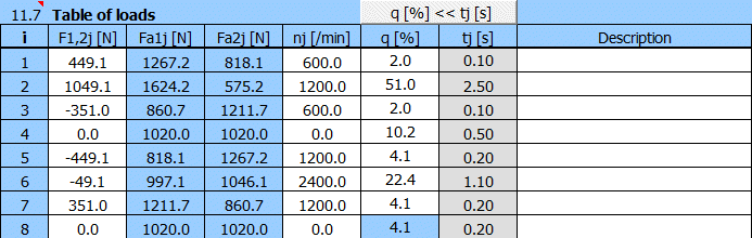
- enter the load of the nut (one by one) in the first column "F1, 2" Positive values in one direction, negative values in the opposite direction.
- in the second "Fa1" and the third column "Fa2" the system calculates the real valuesof the load (in one or the other direction), which also take into account the preload of the nut [11.4].
- enter the corresponding revolutions in the fourth column (always a positive value, the direction depends on the load).
- enter the utilization percentage for each load in the fifth column (the sum must be equal to 100%). In case of unsatisfactory entry, the last valid cell is marked red.
- you can enter the time of individual loads in the sixth (gray) column and after pressing the "q[%]<<tj[s]"("q[%]<<ie[s]”) button the time is calculated and displayed as a percentage in the fifth column.
Index1 and index2 indicate equivalent loads (revolutions) in one or the other direction.
In this section, you can calculate static and dynamic load capacity based on ISO and ANSI dimensions and the relevant screw and nut parameters. At the same time, you can fill out the table of screws (dimensions according to ISO, ANSI) using the calculated values.
After pressing the button, the values from this paragraph are moved to the paragraph "Definition of mechanism, load and screw parameters" [3.0].
Transferred values: i, zu, d1, Dw, Ph, Dpw, , frn, frs
SI units: C0am, Cam
Imperial units: Ti, Pix
This section contains common input parameters for the calculation C0a,Ca,C0am,Cam,Ti,Pi,Pix. By checking the button on [12.3], the parameters from the main paragraph [3.0] are automatically transferred. After unchecking the button, you may enter your own parameters.
Transferred values: i, zu, d1, Dw, Ph, Dpw, , frn, frs
The number of threads is determined by the construction of the nut and is usually specified by the manufacturer. Number of threads between 1.5-6.0 is usually used. The number of threads affects the calculation of static and dynamic load capacity, stiffness and the length of the nut.
Enter the number of balls with no load. This refers to the return system where the balls are returned after one revolution and usually zu = 3. As for return systems where the balls are returned from the final thread back to the first thread, zu = 0. Information on a specific construction can usually be found in the manufacturer's catalog.
The diameter is usually a design issue for the manufacturer. Of course, it is not possible to choose it arbitrarily. The basic condition is that the diameter Dw cannot be greater than the pitch Ph.
0.600, 0.800, 1.000, 1.200, 1.250, 1.500, 1.588, 1.750, 2.000, 2.381, 2.500, 3.000, 3.175, 3.500, 3.969, 4.762, 5.000, 5.556, 6.000, 6.350, 7.144, 7.938, 8.000, 9.525, 10.000, 10.319, 12.700, 20.000, 20.638, 25.400, 30.000, 31.750, 38.100, 40.000, 44.450, 50.000
Standard series of the lead - mm (ISO, JIS, DIN, BS ...)
1; 2; 2.5; 3; 4; 5; 6; 8; 10; 12; 16; 20; 25; 32; 40 [mm]
Standard series of the lead - inch (ANSI)
0.08; 0.1; 0.125; 0.16; 0.2; 0.25; 0.333; 0.375; 0.4; 0.5; 0.75; 1.0 [in]
ISO3408-5 uses 0.86. Value 0.7 is used by certain manufacturers and it is based on (ISO281,2007), (ISO/TR1281-1,2008), (Lundberg, et al.,1947)
Modified load capacity includes additional parameters such as accuracy, parameters and material processing, and it is entered into tables or possibly transferred into paragraph [3.0].
A deviation in hardness has to be corrected by factor fh0, fh
The default value is 654 HV10 (fh0, fh = 1.0). The reduction in hardness affects fh0 and fh. Increasing of the hardness does not affect the calculation.
The static load rating C0 and the dynamic load rating C must be multiplied by the correction factor fac as appropriate for the specific tolerance grade of the screw.
Correction factor fac
IT0, IT1, IT3, IT5 …… 1.0
IT7 ……………………...... 0.9
IT10 ………....…………… 0.7
Influence of material melting process
Ball bearing steel / factor fm value
Air melted ……………...……………….… 1.00
Vacuum degassed ....………………….. 1.25
Electro slag remelted ………………….. 1.44
Vacuum remelted ….……………………. 1.71
Load capacity calculation according to ANSI.
As the basic value a path of 1,000,000 inches is used.
As the basic value a path of 25,400 meters is used.
The calculation contains two basic dimensional tables of screws. Millimeter (ISO) and inch (ANSI). The tables contain all combinations of screw diameters and pitches. Manufacturers adhere to these basic dimensions (or offer more diameters). However, the ball diameters may be freely selected. Based on the analysis of many catalogs of various manufacturers, we have prepared a table of used ball diameters and their assignment to the diameters of screws. This created a series marked as light, medium and heavy. These dimension combinations also appear in the catalogs of manufacturers.
After pressing the button, the corresponding values C0am, Cam (Ti, Pix for ANSI) are gradually filled into the table for the corresponding dimensions –- d1 x Ph x Dw. This calculation and entering values into the table takes some time. You can see the fill indicator in the work window. Do not interrupt the table generation process.
The calculation sets the basic number of working threads to i = 1.0. It does not change the parameters zu, alpha, frn, frs, exp, AH, fac, fm, LIix You can get modified tables for these parameters. However, regenerating tables is suitable for experienced designers who have a detailed knowledge of the issue.
The basic setting of parameters of generated tables are: zu=0, alfa=45, frn=frs=0.55, exp=0.86, AH=654, fm=1, LIix=1000000.
Draft design of the work table driven by a ball screw.
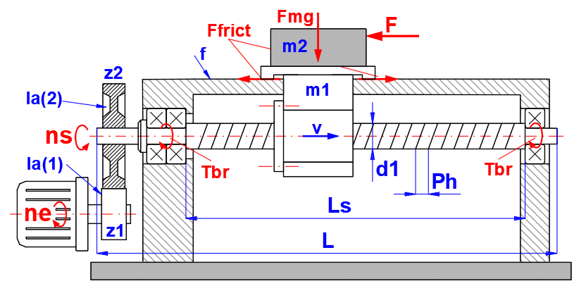
Table weight: m1 = 60kg
Work piece weight: m2 = 40 kg
Force for machining: F = 1000 N
Useful travel: Lu = 1000 mm
Machining speed v = 400 mm/s
Fast feed: vmax = 800 mm/s
Life: 20000h
Guiding surface friction coefficient: f = 0.05
Engine speed: nemax = 1500 rpm
Positioning Accuracy: ± 0.1 mm at max. travel
Repeatability Accuracy: ± 0.02
mm
Ball Screw mounting (ends): Fixed - Supported
First, it is appropriate to address the relationship between the table speed (v), revolutions (ns, ne) and screw pitch (Ph) in paragraph [1.0].
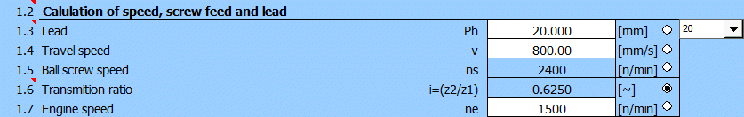
For the first estimate, you can select the values from the picture.
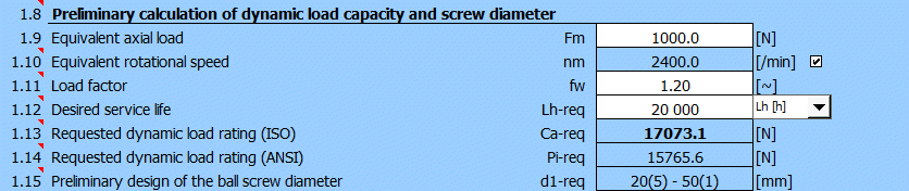
Next, you estimate the equivalent load Fm = 1,000 N, the load factor fw = 1.2 and enter the service life Lh-req = 20,000 hours. The service life is then met by screws with a minimum nominal diameter between 20-50 mm (based on the number of active threads).
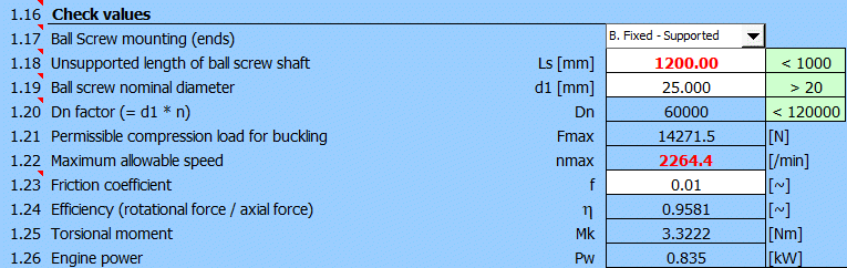
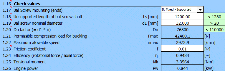
Estimate the mounting range Ls = 1,200 mm (1,000 mm travel length, 150 mm nut length, 50 mm mounting overlaps). For the nominal screw diameter d1 = 25 mm, the recommended max. value Ls < (40xd1) is exceeded, but mainly the critical revolutions (nmax) are exceeded. Therefore, use a screw with diameter d1 = 32 mm, which meets the basic check requirements.

The required accuracy for Lu > 1,000 mm can be achieved by selecting accuracy IT3.
Open paragraph [3.0] and transfer the values from paragraph [1.0] by pressing the "[1.0]>>[3.0]" button.
It is also necessary to define other drive parameters more precisely. This refers to lines [3.3-3.7]. Fixed mount on one side, support on the other side and a preloaded nut.
In the vast majority of cases, we do not know the exact screw load. Therefore it is advisable to use the calculation from paragraphs [10.0] and [11.0].
In this section we shall define the load in detail. After checking the button on [10.2], the valuesfrom paragraph [3.0] are transferred. Now, you may gradually add the remaining values.
Turning of the mechanism b = 0
Weight m = 40 + 60 = 100 kg
Moment of inertia Ia (2), Ia (1) may the estimated in paragraph [9.0].
![]()
![]()
Gear ratio i = 0.625 (see paragraph [1.0])
Coefficient of friction f = 0.05
The definition table looks like this:
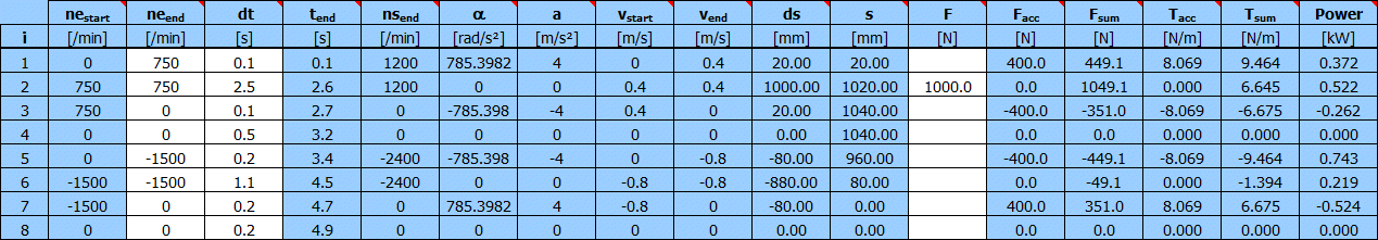
Line 1: neend=750; dt=0.10; F=0 ............... Start-up from 0 to 750 RPM (acceleration)
Line 2: neend=750; dt=2.50; F=1000 .......... Machining work cycle at 750 RPM machining force is 1,000N
Line 3: neend=0; dt=0.10; F=0 ............... Braking from working speed down to 0. (deceleration)
Line 4: neend=0; dt=0.50; F=0 ............... Time delay (for example for tool readjustment)
Line 5: neend=-1500; dt=0.20; F=0 ................ Start up for reverse run to -1,500 RPM (acceleration)
Line 6: neend=-1500; dt=1.10; F=0 ................ Reverse run at -1,500 RPM
Line 7: neend=0; dt=0.20; F=0 ............... Breaking down to zero RPM (deceleration)
Line 8: neend=0; dt=0.20; F=0 ............... Time delay (for example for tool readjustment)
Revolutions meet the specification, the times are designed so that the condition of the maximum travel length Lu = 1,000 mm is met (row 2, column ds) for the table speed of 400 mm/s or rather 800 mm/s for reverse.
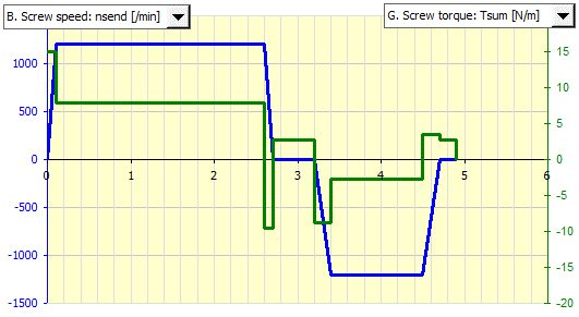
The time cycle is 4.9 seconds. The graph shows the screw speed and the forces acting on the nut and screw.
Since the screw load is not constant, it is necessary to convert the variable load to an equivalent load, which is used to calculate the required dynamic load capacity Ca.
In line [10.23] – press the “[10.0]>>[11.0]" button. This will transfer the forces and revolutions into the load table in paragraph [11.0].
 =>
=>
Now you enter the value of the nut preload. From the preliminary design we know the value of the required dynamic load capacity Ca-req = 17,000 N [1.13]. The preload of the nut is usually 10% of Ca. Enter the value Fpr = 1,700 N at line [11.4] and the coefficient Fop = 0.6 (according to ISO3408-5) at line [11.6].
Transfer the calculated values of the equivalent load and revolutions back to paragraph [3.0] by pressing the "[11.0]>>[3.0]" button.
At this point you have defined the screw load and the required load capacity very precisely.
You have two options when selecting the screw.
The table of screws and their load capacities was generated according to ISO3408-5 or rather ANSI_B5.48 – for inch dimensions. If you do not know the specific manufacturer, it is possible to choose from this table.
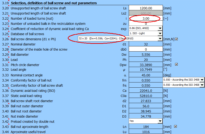
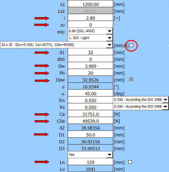
A 32x20 (d1xPh) screw should be selected from the selection list based on the preliminary design. The diameter of the ball Dw and the dynamic load capacity Ca are given in parentheses. The basic Ca load capacity for one working thread is 8,500 N. It is therefore necessary to set the number of turns of the nut at i = 3. The value of dynamic load capacity is 22,041 N, that is a greater value than the required value Ca-req = 20,227 N.
If you are selecting values directly from the manufacturer's catalog, the following procedure is probably the best.
- Select the adequate screw size from the table (this will preset the correct dimensions)
- Uncheck the button to the right of the screw selection list.
- Enter the values from the manufacturer's catalog at the marked lines (many dimensions will already be pre-filled correctly).
An example of offered nuts in the required size and load capacity supplied by several manufacturers.
| ID | d1 x Ph | Dw | i | Ln | Ca | C0a | K | D1 | Manufact. |
| 1 | 32 x 20 | 3.969 | 2.8 | 159 | 21751 | 49536 | 842 | 50 | KSK |
| 2 | 32 x 20 | 5.556 | 2 | 177 | 31400 | 81100 | 790 | 55 | PMI |
| 3 | 32 x 20 | 3.969 | 3 | 178 | 19000 | 54300 | 680 | 50 | HIVIN |
| 4 | 32 x 20 | 4.763 | 4 | 216 | 31900 | 89140 | 940 | 54 | HIVIN |
| 5 | 32 x 20 | 5.000 | 4 | 70 | 29700 | 59800 | - | 53 | Thomson |
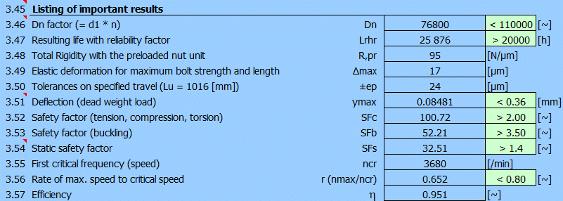
At the end of paragraph [3.0] there is also an abbreviated list of results. It is used for a quick navigation providing that you try to “tune” up the selected input parameters. Complete results are available in the "Results" section.
Information on options of 2D and 3D graphic outputs and information on cooperation with 2D and 3D CAD systems can be found in the document "Graphic output, CAD systems".
After unchecking the button on the right, you may enter the number of threads which is to be shown on the screw/nut drawing.
Pre-filled values are based on the calculation.
It indicates by how many turns the left edge of the nut will be shifted relative to the left start of the screw.
Information on setting of calculation parameters and setting of the language can be found in the document "Setting calculations, change the language".
General information on how to modify and extend calculation workbooks is mentioned in the document "Workbook (calculation) modifications".
ISO 3408-1:2006
Ball screws - Part 1: Vocabulary and designation
Vis a billes - Partie 1: Vocabulaire et designation
ISO 3408-2: 1991
Ball screws - Part 2: Nominal diameters and nominal
leads. Metric series
Vis a billes - Partie 2: Diametres et pas hélicoIdaux, nominaux. Serie métrique
Kugeiroligewinde - Teil 2: Nenndurchmesser und Nennsteigungen. Metrische Reihe
ISO 3408-3:2006
Ball screws - Part 3: Acceptance conditions and acceptance tests
Vis a blues - Partie 3: Conditions et essals do reception
ISO 3408-4:2006
Ball screws - Part 4: Static axial rigidity
Vis a blues - Partie 4: Rigidite axiale statique
ISO 3408-5:2006
Ball screws -Part 5: Static and dynamic axial load ratings and operational life
Vis a billes - Partie 5: Charges axiales statiques et dynamiques de base et
durée de vie
ISO 286-2:2010
Část 2: Tabulky normalizovaných tolerančních tříd a mezních úchylek pro díry a
hřídele
Part 2: Tables of standard tolerance classes and limit deviations for holes and
shafts
Partie 2 : Tableaux des classes de tolerance normalisées et des écarts limites
des alesages et des arbres
Teil 2: Tabellen der Grundtoleranzgrade und GrenzabmaBe für Bohrungen und Wellen
DIN ISO 3408: the ISO standard has been adopted directly as the DIN standard
JIS B1192-1997 is similar to DIN ISO 3408
JIS B1192-2018 putting the JIS standard in harmonization with the ISO 3408
DIN 69051-5
Machine tools - Ball screws - Part 5: Mounting dimensions for ball nuts
Machines-outils - Vis a billes - Partie 5: Dimensions de raccordement pour
écrous
ANSI B5.48 - 2013
Ball Screws
Company cataloques: THK, PMI, KSK, NSK, SKF, HIWIN, KURODA, NOOK, THOMSON, Steinmayer, MANESMAN
^