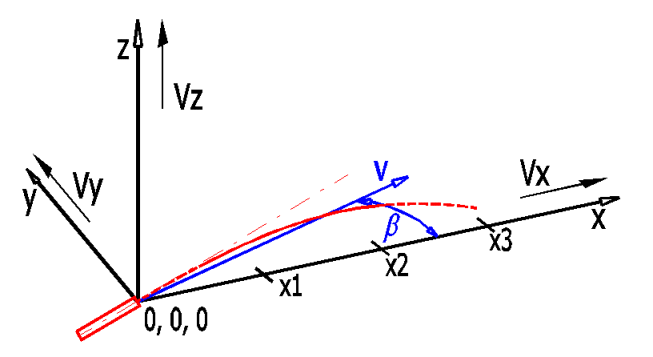
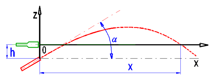
The program is intended for simple simulation of the firing of various types of bullets. The program solves the following tasks:
Data, procedures, algorithms and informations from professional literature and the catalogues of the ammunition manufacturers are used in the calculation.
User interface.
Download.
Purchase, Price list.
Information on the syntax and control of the calculation can be found in the document "Control, structure and syntax of calculations".
Information on the purpose, use and control of the paragraph "Information on the project" can be found in the document "Information on the project".
The following formulas are used in the calculation:
p [kPa] = p0 / (1 - (0.0065 * h) / (t+0.0065 * h + 273.15)) (-5.257)
p0 ... Air pressure at sea level (101.32) [kPa]
h ..... Altitude [m]
t ...... Temperature [°C]
Q [kg/m^3] = (p * 1000 * 1 * 0.02895) / (8.314 * (273 + t))
Fd [N] = 0.5 * Q * T * Cx(M) * S * v^2
Q ... Air density [kg/m^3]
T ... Bullet coefficient of form
Cx(M) ... The air resistance coefficient depends on the velocity and type of the
bullet
S ... Facing [m^2]
v ... bullet velocity [m/s]
BC [lb/in2] = m / (d^2 · T)
m ... Bullet mass [lb]
d ... Bullet diameter [in]
T ... Coefficient of form
T = m / BC / d^2
m ... Bullet mass [lb]
d ... Bullet diameter [in]
BC ... Ballistic coefficient [lb/in^2]
Fg [N] = m * g
m ... Bullet mass [kg]
g ... Gravitational acceleration [9.81m/s^2]
It is included in the calculation of aerodynamic resistance and position of the bullet.
Not included in the calculation.
Not included in the calculation.
The calculation is based on simple composition of forces, velocities and gradual calculation of parameters over a given interval dt. The interval can be set manually (calculation runs in 10,000 steps) and/or select an estimate for the entered bullet, entered distance and elevation.
In this paragraph, select the units, temperature , altitude and wind speed.
Select the desired calculation unit system from the selection list. Upon switching units, all the input values shall change immediately.
Select air temperature, and upon pressing the button on the right side, the temperature value is entered according to MSA (simplified model of the Earth’s atmosphere). At the ideal sea level, the air temperature is 15°C and pressure 1013.2hPa. Up to 11km, the temperature drops with increasing height at the rate of 0.0065°C/m).
Upon picking the button, you can enter any value independent of [1.1-1.3].
Define wind action as:
1.The wind speed and angle in relation to the firing axis.
2.Wind speed at the defined points on axes x, y, z.
Use the switch on the right side to select the input method.
The buttons are used for conversion and transfer of the values from one system to another.

It states the number of defined points, which shall be used in the calculation. The last entered value is valid until the end of the flight path.
In this paragraph, you select/enter the firing parameters (diameter, weight, initial velocity, BC) and the required parameters for calculation of the ballistic curve (firing angle/distance, super-elevation). The calculation is executed by pressing the “Calculate” button above the graph of values.
From the selection list, pick the sample bullet (weapon). The parameters can be modified after selecting the button on the right side of the selection list.
It gives the degree to which bullet is worse (better) than the sample bullet from the selected aerodynamic resistance function [2.10].
The BC is related to the given aerodynamic resistance function, most often to G1. The BC value can usually be obtained from the manufacturer.
The drag coefficient depends on the velocity of the bullet. The most commonly used function C(M) is G1, for which most manufacturers also state the ballistic coefficient. Select the aerodynamic resistance function from the list for bullet A and B. You can define the actual progress of function C(M) on sheet "DragC(M)". The velocity is given in the table and graph in relation to the speed of sound.
The value of the aerodynamic resistance function related to the bullet velocity (M) is given in the graph.
From the list, select if the solution and curve for only bullet A and/or the curves of both bullets should be visualised.
Enter the sighting axis height (h) above the muzzle level.

You have two potential solutions. You make your selection with the switch on the right side.
1. When selecting the impact angle, the complete
path of the bullet is calculated for 10,000 points with selected calculation
step dt [2.19]. By setting dt, you set the length of
the trajectory, for which the parameters are calculated.
2. When selecting the sighting distance, the value of
dt is estimated and the results are shown and cut to use a flat graph.
Enter the sighting distance and sighting elevation [2.15].
You can enter the calculation step in [ms] using the slide, or by directly entering the value. The calculation step determines the time interval for which the flight of the bullet shall be calculated.
During the calculation for the given sighting distance [2.14, 2.15], the number of steps used is displayed. Calculation for the given firing angle [2.13] is done for 10,000 steps.
Lines [2.23, 2.24] show the input parameters for bullet A and B.
Select the graph you desire to visualise from the list.
The numerical values of the graph are shown on the sheet "Data1".
Summary tables. The tables summarize all the most important fire parameters for one or two bullets (selected in [2.11]).
The table contains the bullet trajectory height deviation for the specified distances.
Use the “Divide path” button to divide the specified end of the flight path to 10 equal parts.
Upon pushing the button, the lateral deviation is calculated for 5 specified wind speeds. The wind influence is considered constant and perpendicular to the bullet trajectory for the purposes of calculation.
More exact specifications can be set in par. [1.7], but only for the calculation of the graph [2.25].
The table shows the bullet flight time for the specified distances.
The table shows the lead for the specified motion speeds of the target. The considered target motion direction is perpendicular to the flight path.
Information on setting of calculation parameters and setting of the language can be found in the document "Setting calculations, change the language".
General information on how to modify and extend calculation workbooks is mentioned in the document "Workbook (calculation) modifications".